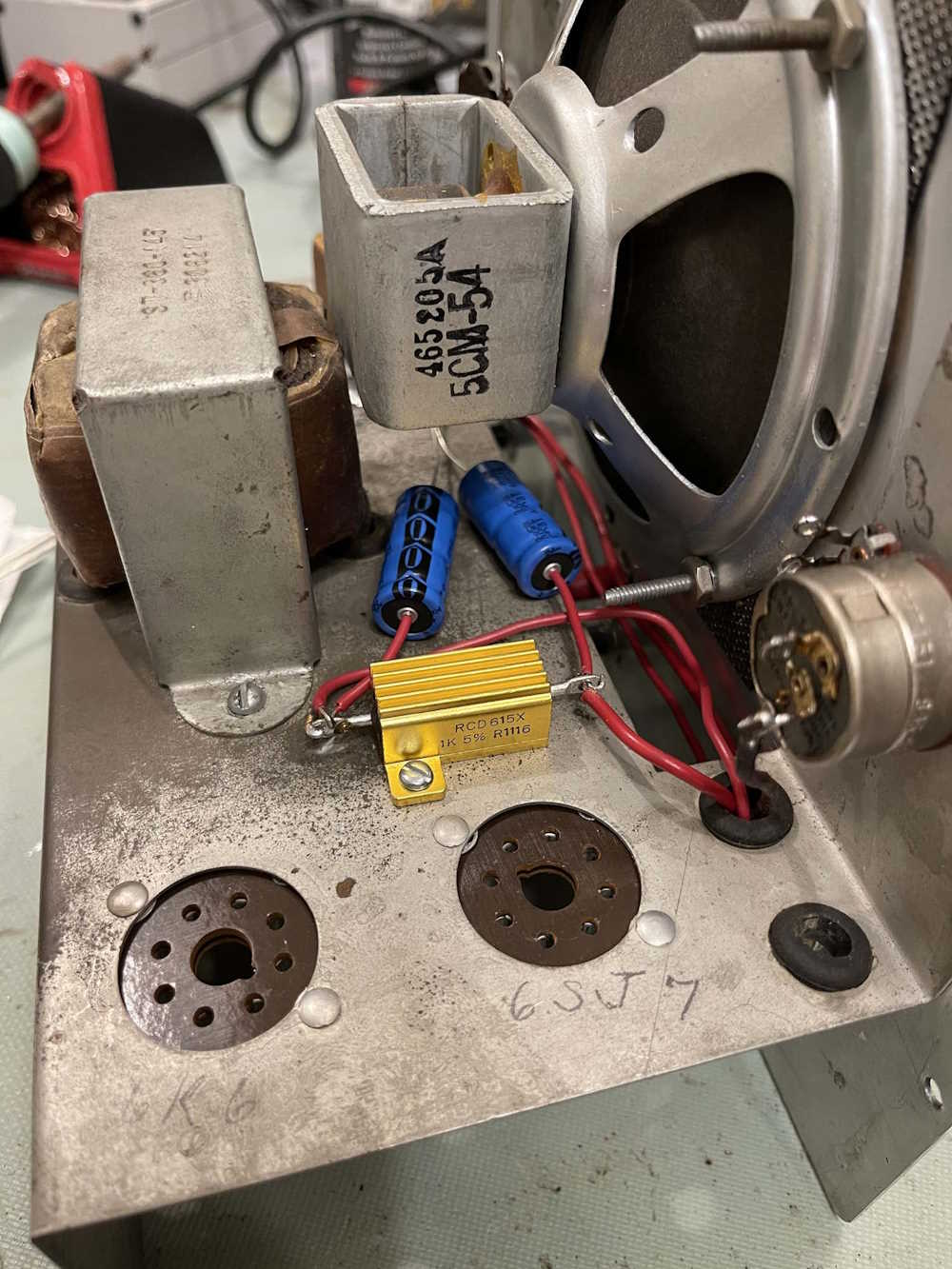
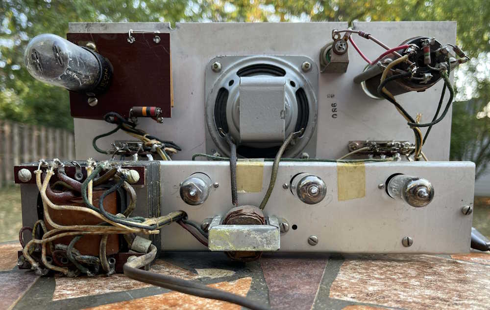
I had to make some executive decisions in where to place things here, since I have more going on under the chassis. Instead of using a leaded device for the power supply dropping resistor, I chose to use a non-inductive aluminum cased resistor. Is a 25W resistor overkill here? Yes it is. Do I care? Not at all. I also moved the filter capacitors on top of the chassis since the old device with it’s mount clip is now gone. Two holes were drilled to mount the resistor - theoretically this should sink into the chassis as well, but the resistor is more than capable of dissipating the 2W the original was designed for without any heatsink at all. One side has the connection from the rectifier and a filter capacitor, the other is connected to the output transformer, and will run to various points in the circuit itself.
The only thing left to connect to the filters is that second connection, then it can be soldered.
Will this cause some hum? Maybe, but the audio output transformer lead was already as long as it is now, so who knows.
(There’s lots of hum in this unit, so I didn’t really care about this kind of layout. The audio input line is essentially a giant antenna that stretches the entire length of the device, so - yeah, whatever it is, it is.)
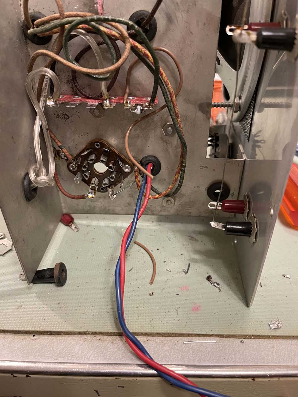
You can see the filters, laying against the chassis, going to a ground point near the output transformer.
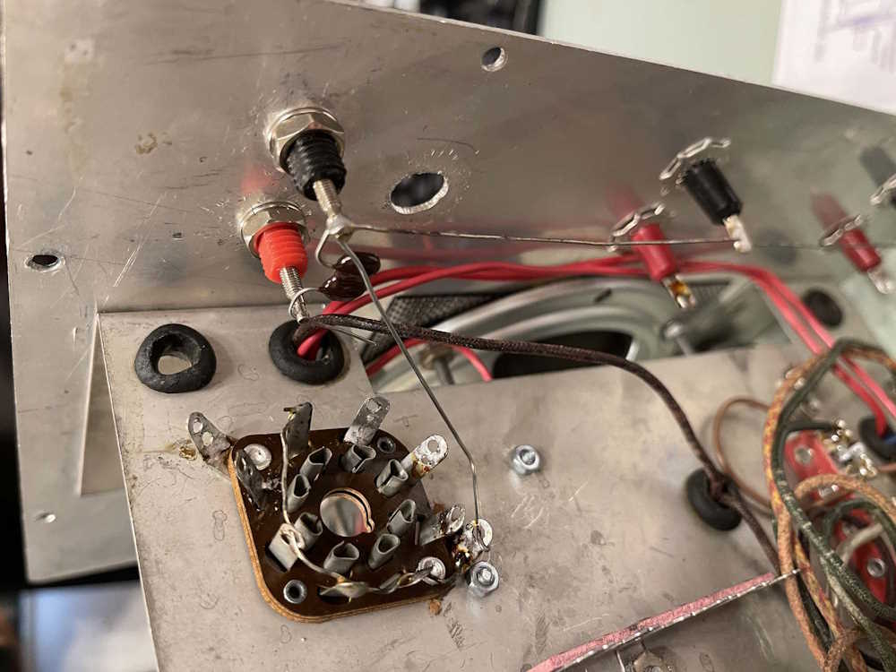
I also connected the grounds at the input, and soldered one side of the 50pF capacitor down.
(I don’t know why I ran that wire from ground like that. I’m a stupid wereboar and got rid of it later.)
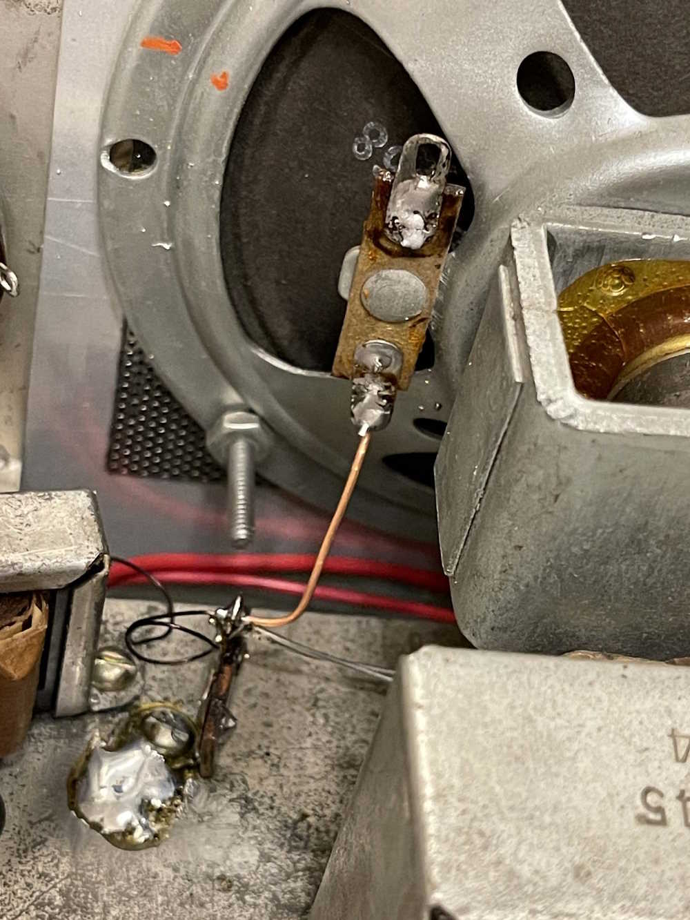
Last, is the ground point on the audio output transformer side. The transformer itself is a little smaller than the holes drilled, so was this a replacement? No idea, but I went ahead and drilled a new hole for it so it’s not flopping around on the chassis. The original transformer mount hole had a small ground tab in it, I went ahead and recycled one of the terminal strips from the bottom as a ground. This point has both filters, the speaker, and the output transformer connected to it. Since this is a fairly important ground, I hit the chassis with some scotchbrite and soldered the tab in place, insuring a nice, solid connection.
There’s a bit of solder splatter there to clean up.
You’ll notice that the output lead for the transformer is coiled up. I’ve been trying to avoid trimming any length from parts left on the chassis, just in case.
Just to note, I am in no way concerned with making this look original. It’s going to be a working device, and that’s it. I’ve tried to select good parts, so barring tube failure this thing should work for many years - and I may just get a set of tubes regardless to populate the device when it’s ready for service.
Stay tuned for part 6c, a few more connections and we’ll test the power supply!
Some years ago, I was contacted by a company that manufactured building products, as well as electrical devices to handle said building products. This was in regards to a technician position - more of an engineering tech - at the company’s headquarters. They’re just a shade under 2 hours from me, travelling on some country roads - there’s no way I could live here and drive there.
This was kind of an odd process, we had a phone screen and an on-site interview first, and a couple weeks later they asked me to fill out some online paperwork - applications and some assessment thing. During this time period, I had been unable to find out any information about the pay rates for the position. When we got to the hot and heavy part, I asked.
You can see the recruiter’s response and our email chain in the image.
I was told the salary range was confidential, but the recruiter could advise me based on my current salary if we should continue. I provided said information.
The eagle-eyed among you will notice the recruiter never really affirmed that it would be worthwhile to continue. Just that they had reviewed it. I didn’t notice that at the time. You’ll also notice I made the mistake of not saying what it was I wanted.
Did I get offered the job? Yes. Was it worth the time? It was a little more base, but was a net loss when I factored in medical and other items that my current employer gave employees at the time. I had to turn it down.
The recruiter and interview team called me. They wanted to know what they needed to do to get me in the door. I said “it’s the money.” It’s just not worth the few cents more you offered. You know where I live, you know what I make, you know I’d be leaving everything behind and essentially starting over with a higher-skill job. Make me a real offer.
Well, that went nowhere, and that’s the last I heard from the company.
Now? If I couldn’t get an answer up front about that salary range, I’d simply thank you for your time. It’s confidential? No, it’s not, and I’m going to be running away from your company.
It taught me to get all the information up front. If someone tries to play games and hide that info? Turn around and leave. That’s all.
No, this doesn’t help you keep your digimon in check. At least, I don’t think it does…
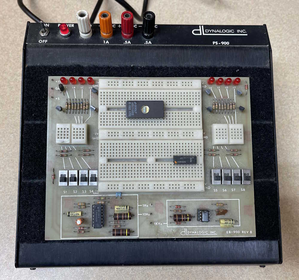
I picked this interesting digital trainer device up at the recent Cleveland hamfest. Why? I’ve been getting back into experimenting now that I have a bit more time, and I don’t really have something like it. Sure, I have breadboards and things, but this has some amenities like indicators, switches, and a couple of clocks onboard, as well as power supplies. It’s made by a company called Dynalogic, and they specialize in modular breadboard systems for schools - this one even has “University of Toledo” (Ohio) on the bottom.
(Dynalogic has a website, but the last date is 2010. Not sure if they’re still in business or if they just don’t update often.)
It looks like a piece of late 1970s kit with the black case.
The power supplies, while operational, are a little low. 5V was 4.82, and both 15s were 14.4. Probably some bad caps in there, which wouldn’t be surprising for the age. I’ll open it up this winter and give it a check.
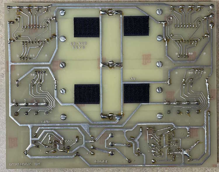
Dynalogic’s breadboards are made to be modular, and this one is no different. The black material under the board isn’t static foam, it’s velcro. You buy the base, then put whatever board you want on it - including stuff you make yourself. It’s really an interesting way of doing it, because there’s no special things needed - just put a couple spots of hook on the back and drop it on the box.
This unit appears to require the +5 and +15 volts, which is input at the little jacks on the top left- you’re supposed to run a standard breadboard wire down to them. This gives you a metal contact to tap from and run the rest of the devices on the board. As stated before, it features 8 indicators, 8 switches, 3 clocks, and some prototyping space (the chips on the breadboard were there when purchased and have no relation to the board.) Pretty simple in all, this is enough to do basic circuitry and give you some I/O. Nothing on here except some 555s.
The back of the board indicates that it’s hand soldered. Whether this was from Dynalogic or by a student, I don’t know. But in wasn’t wave soldered, that’s all I can tell you. You can see the velcro hooks.
Overall? This is a nice piece for the few bucks I gave for it, and it was drawing a lot of interest when I took it with me. I think, after cleaning up the supplies, that it will find a nice home on the bench.
As stated earlier, this was my first time attending this show, and I didn’t leave unhappy. It consisted of about 4 rows of vendors in the parking lot, and a small building mostly full of vendors. There was certainly plenty to look at, and prices were generally very reasonable. Everyone was willing to deal, so I’ll blame that for my haul.
The fairgrounds are tucked behind some houses, so we had to make a go-round and get back to the entrance, having turned the wrong direction the first time. But no big deal, we arrived at 8:15 and spent about three hours browsing the warm, sunlit aisles of stuff.
The trip home warranted a stop in Coshocton for lunch and a brew at Wooly Pig, a place I highly suggest you check out if you are in to that sort of thing
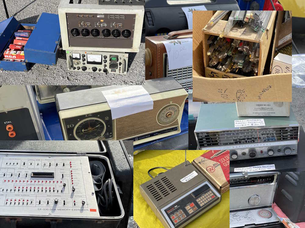
Here’s what you’re waiting for, all of the things I saw at the show.
An Aerovox capacitor tester - missing the rest of it's oddball probe.
Random audio gear and an old SW radio.
I love those old Bearcat scanners and their 1970s colors.
Books. I took home his small collection of crystal radio stuff.
A butt set. Not a collection of behinds, but a telephone test handset.
A device to exercise a CDC disk system. There was a stack 'o disks on the ground.
The guy had boxes of chips. I took home some unusual dot matrix displays.
A nice example of a CT455. It needs a little work on the radio, but plays well.
A digital trainer doesn't always work with digimon.
You don't see a lot of those HP lunchboxes these days.
A nice National Radio in National grey-blue.
A test device marked Philco-Ford.
Power strips for 30 amps. A friend took this home.
Just some random things.
Random radios. The Zenith portable was kind of cool.
A reel-to-reel player. For reels. Of tape. On reels.
Those little rat shack speakers weren't bad for the day.
A baby Tek scope holding the ground down.
Not sure, but I heard the word “SONAR” mentioned.
Staple guns. I took the hand brad nailer in the middle home.
A lot of tube testers at this show.
150 watts to measure a voltage - if you dare!
The bakelite Zenith was in awesome shape, especially for $35.
I’ve attended a lot of shows this year, mostly because I’m unsure as to what’s going to happen later - if some sort of unrest begins, that may cancel shows for a while. So … git while the getting’s good, I guess!
I’m not sure if I’ve been to this one, I seem to remember a small show in Southern Ohio that I went to back in the 90s, my first small “Not Dayton” hamfest. It had some decent things, but was a really small show - I still have the big NIXIE counter purchased from that event.
Regardless, “If I Feel Like It,” I’m going to head down there and check it out.
The Scioto Valley Amateur Radio Club Hamfest
Saturday October 5th 2024
8A - 12P
Admission $5
This post starts the rebuilding of the Eico 145 signal tracer I’ve been working with since picking it up at the Breezeshooter’s Hamfest in 2023. This will consist of probably 4-6 parts (maybe more,) depending on how much time I have to work on it.
The first part is starting the power supply - I’m not going to do this exactly as the manual says, since there will be some extra stuff on the chassis. I’m going to do the power supply completely, then generally follow the assembly manual for the rest of the device.
First things first, I noticed the 4 position terminal strip closest to the rectifier tube couldn’t be mounted like the assembly drawing shows - it’s too long! That’s why the original builder chose to turn it to the side. No matter, I needed more positions so I put a longer strip in and turned it perpendicular to what the manual said. This gave me some room to add the two heater cutback diodes at the top of the strip. I didn’t bend those leads in, but chose just to drop them in the strip and solder. No, that’s not the way you’re supposed to do it, but I made sure the solder joint was solid.
I’m trying to keep the AC all in one spot, except for the filaments which obviously have to run across the chassis.
One thing you should note here is that one side of the filaments, and the center tap of the primary all go directly to chassis. This may seem kind of odd, but it helps reduce the hum present in the unit. Instead of connecting grounds everywhere, I tried to keep all of the AC running to the same ground tab. We’ll see if that makes any difference.
It is kind of a mess here, but I didn’t want to cut wire off the transformers, so I looped it where needed, and used the length to try and neatly run things to their destination. It is what it is.
Everything except for the filaments, and the AC return from the switch has been wired in. I’ll do the rest once I get the proper color of wire (more on that later.)
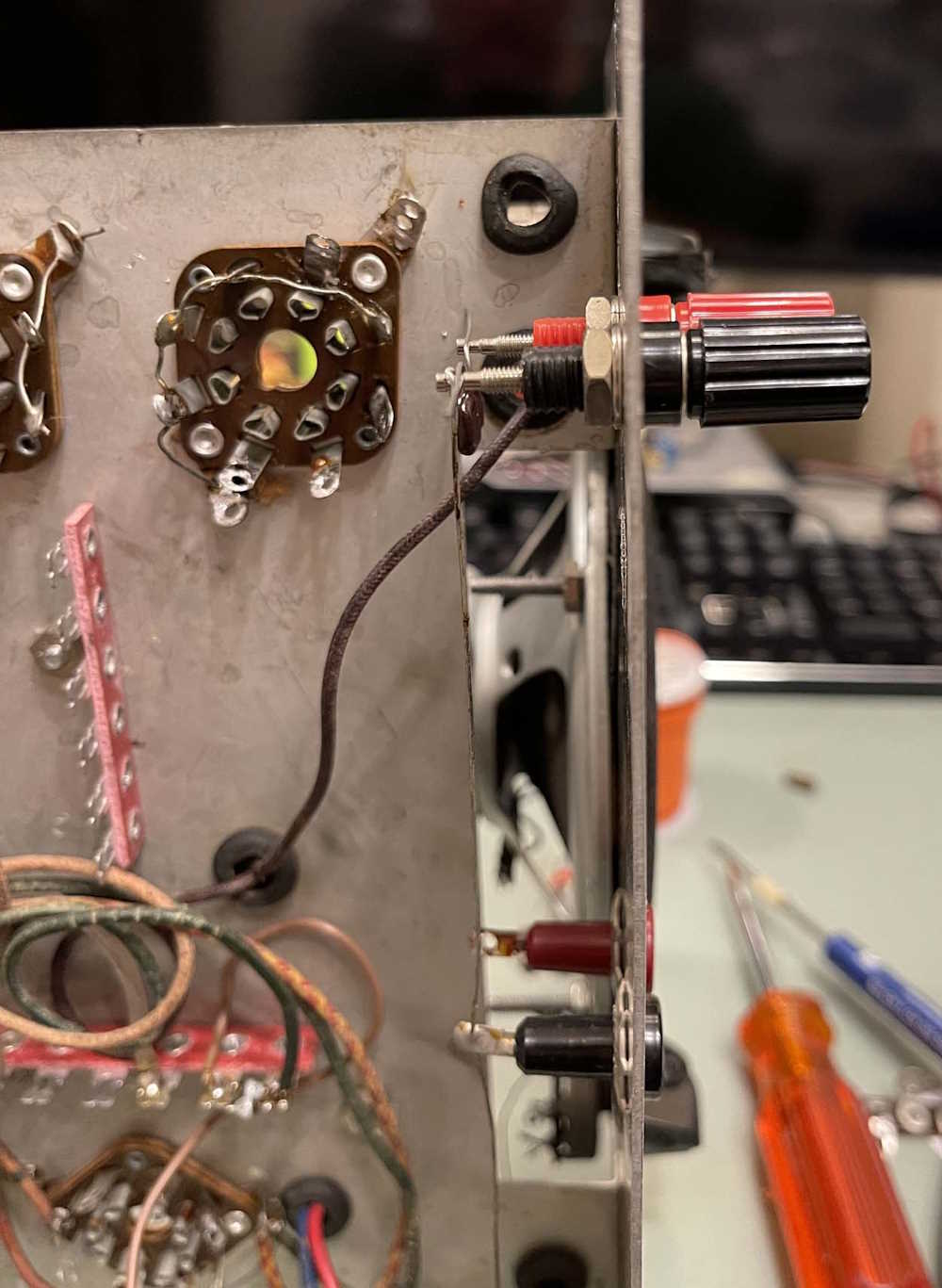
The only other part I did tonight was replace the front panel pin jacks on the input with a nice set of banana jacks. These are much more useful to me than the pin jacks. Note the new 50pF mica laying on the terminals, this was being sized but I don’t want to solder it in until I get some more wire.
Next part will involve placing the new filters and the rest of the power supply components.
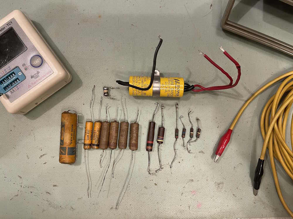
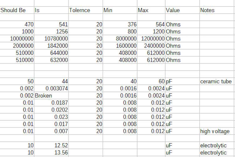
It doesn’t really mean anything, but I wanted to check all of the components I took out of the Eico 145 Signal Tracer that’s currently on my bench. There was nothing unexpected here, most of the parts had drifted out of tolerance - or in one case, broke upon removal.
I didn’t test anything for leakage, and that’s probably where the majority of the issues would be.
The resistors were all carbon comp 20%, and most of the capacitors paper wax - assumed 20%. One ceramic tube capacitor was present - supposed to be a mica - as were the electrolytic filters. The electrolytics are assumed to be -20% / +100%. ESR on these wasn’t bad, but they’re due for replacement regardless.
Some capacitors weren’t present in the device, I’m not sure if they were never there or if they were removed for some reason.
Here’s the parts and their values, no particular order.
Next step is to start rebuilding. I’m going to deviate from the assembly diagram somewhat and build the power supply fully before moving on to the next part.
The 50th Annual Cleveland Hamfest (And Computer Show) is happening this weekend.
I’ve never been to this one, so I’m not sure what to expect - but 50 years worth seems to indicate that it’s well attended enough to keep going.
I decided to check it out because prices this year have been incredibly cheap due to the bad economy, and it’s giving me a chance to pick up some things I’ve wanted but couldn’t afford in the past. I’m also looking towards things getting really strange later - who knows what’s going to happen and how it’s going to affect this stuff. Get it in now while it’s available!
The Cleveland Hamfest and Computer Show
Berea Fairgrounds, Eastland Entrance
160 Eastland Rd
Berea, OH 44107
September 22 2024
8A - 12P https://www.hac.org/
One of the things I like to do before closing up a device (permanently, or for a while) is to do a good photo retrospective showing layouts, parts, etc. It usually will be submitted to someplace for posterity, and displayed here for your enjoyment. You can also check out Radiomuseum, who accepted a number of pictures for their exhibit on the device.
I had to resize these - they were simply too large and were causing some issues.
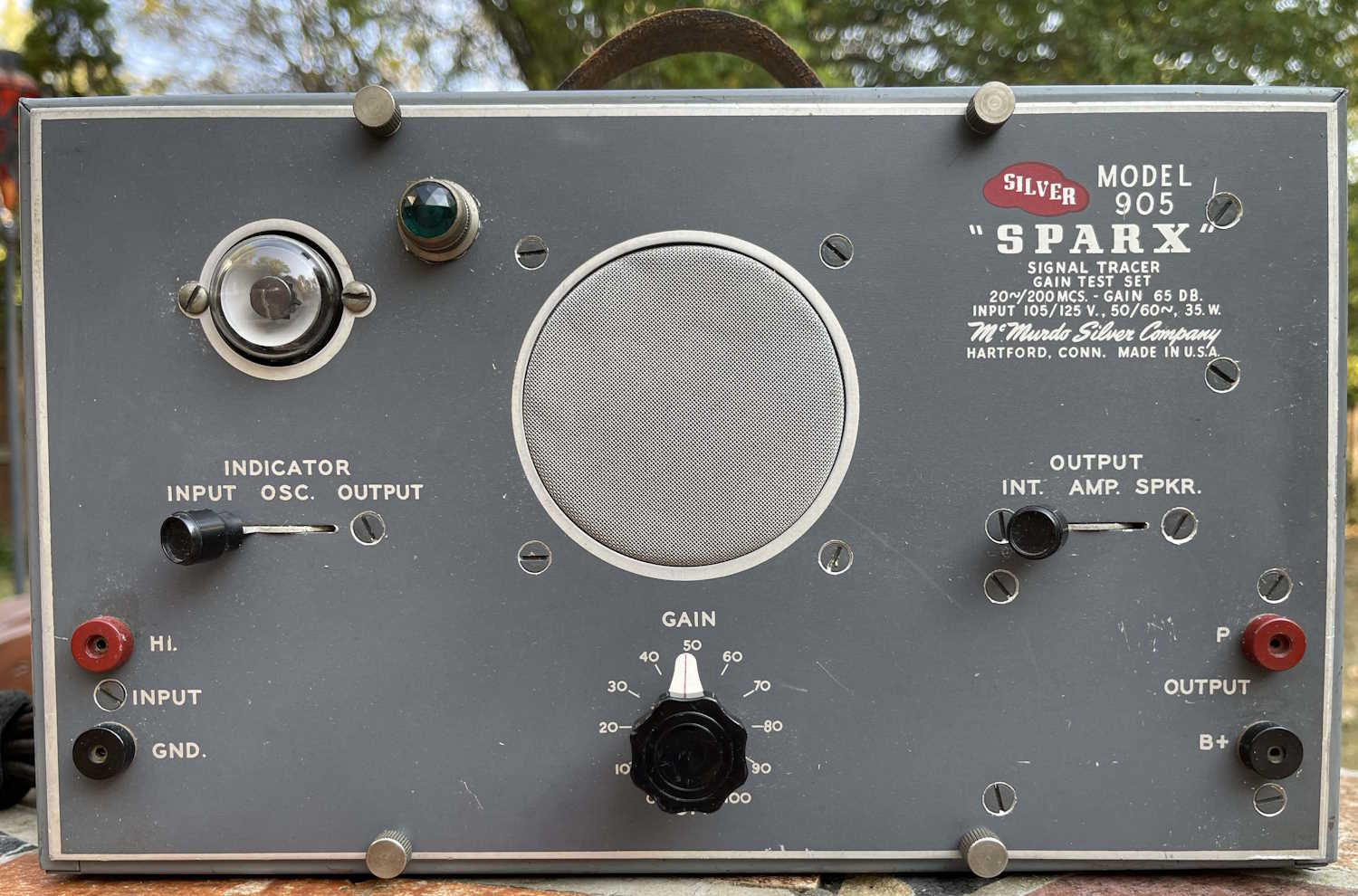
The 905 tracer is going on display for the moment, so here are some photos of all the goodies inside:
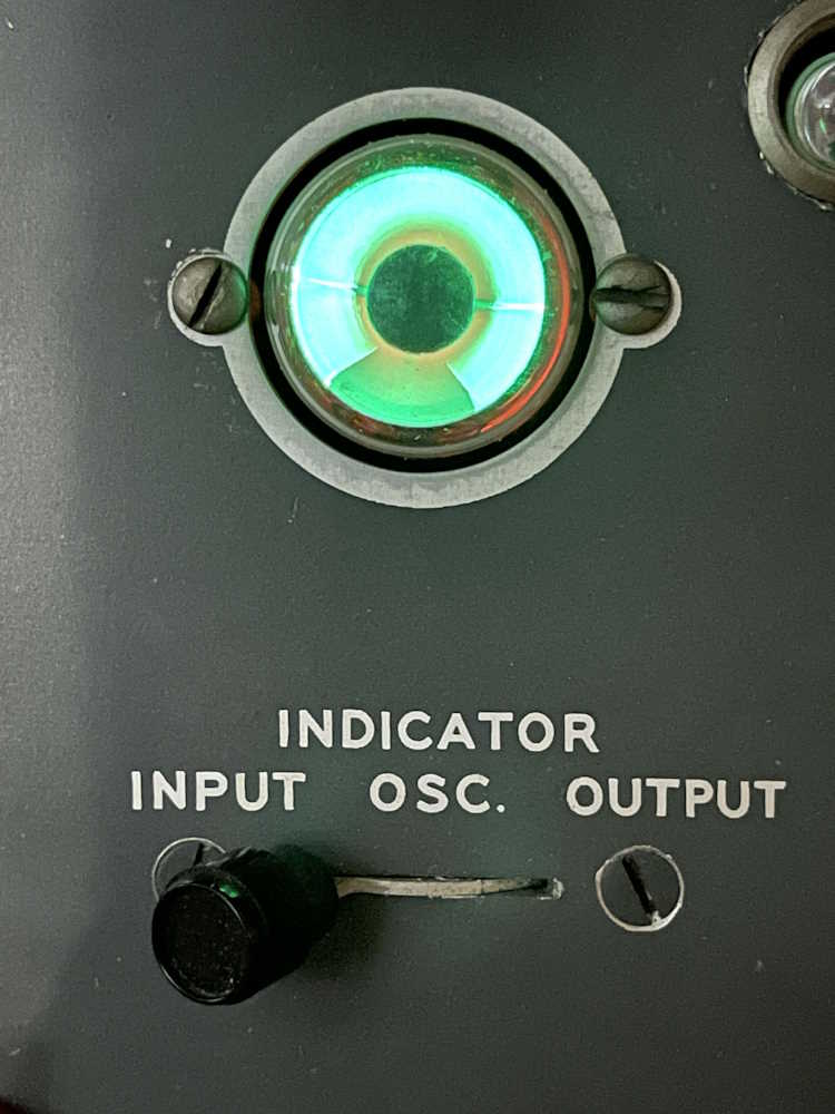
The front of the unit. The pilot lamp was not original on this unit, and this one received a nice LED bulb. I pulled the screen out and knocked the dents out as best I could, you can still see a little wrinkling there.
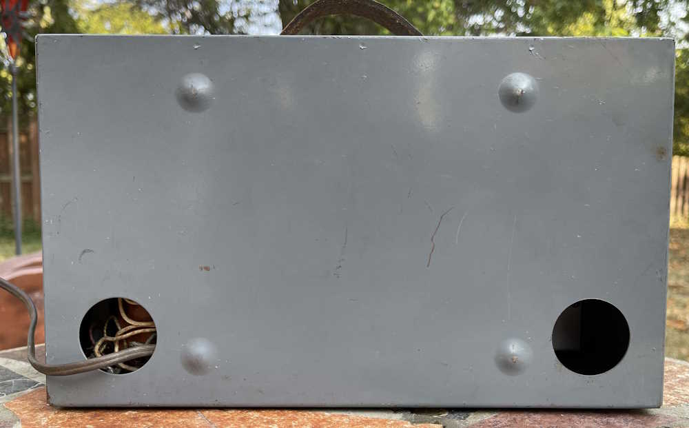
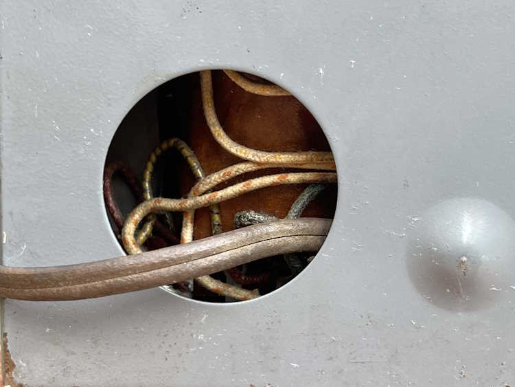
Here’s the back. Note the big holes for cables at the bottom, this one only has a power cord.
You can reach in and touch the transformer taps. Designed for those who have some sense.
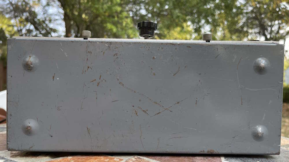
This unit has little dimples for the feet, so no crushed rubber.
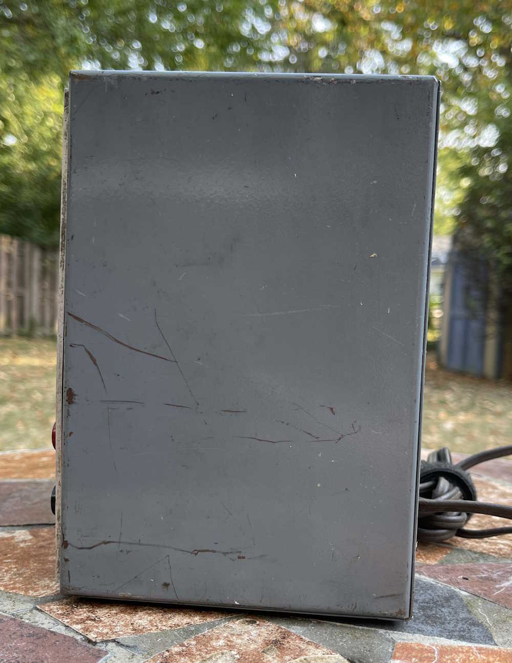
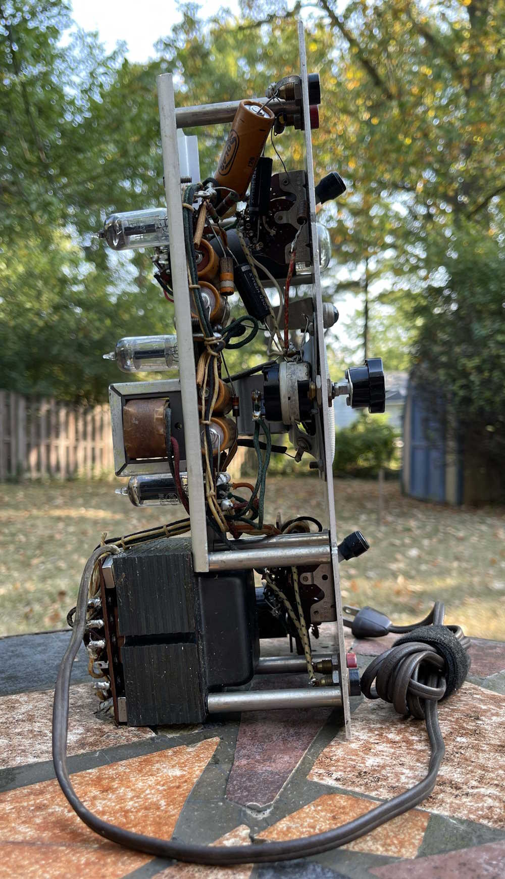
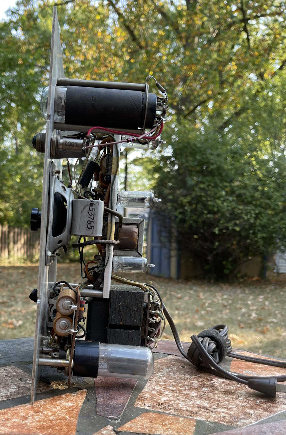
The side. It’s…the side.
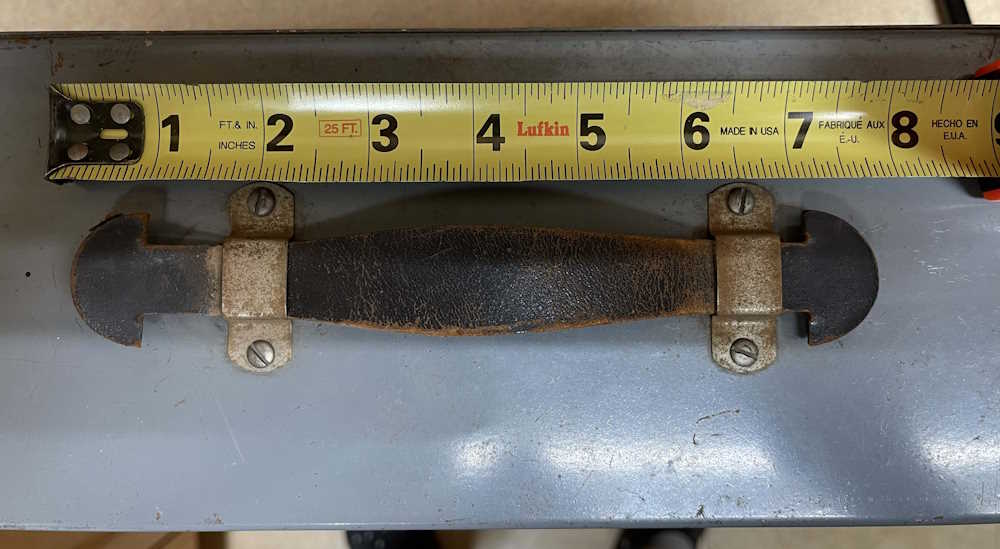
The device uses a leather handle. It’s still intact, but I’ve tried not to use it.
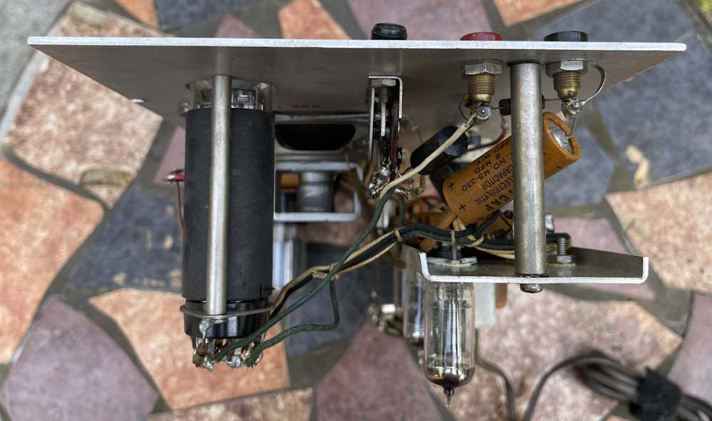
Here’s some shots of the chassis:
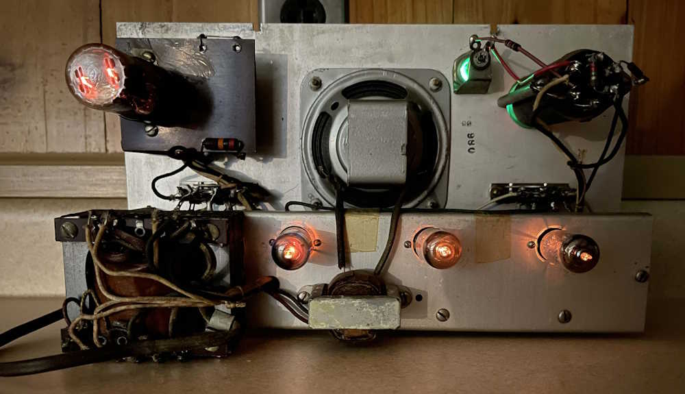
The best part - the tubes are all lit up:
In all, this is a pretty cool device and doesn’t have a lot of things other than it’s basic function of amplifying sound. For now, it’s going to be a showpiece - but eventually it will be used as a small amp in my main room, as I already have a tracer I’m working on rebuilding. I am planning on replacing filters and other electrolytics on this at some point, so stay tuned!