An Eico 145 Signal Tracer - Part 6e - The rebuild is done.
Wednesday, October 16, 2024 at 16:34:47
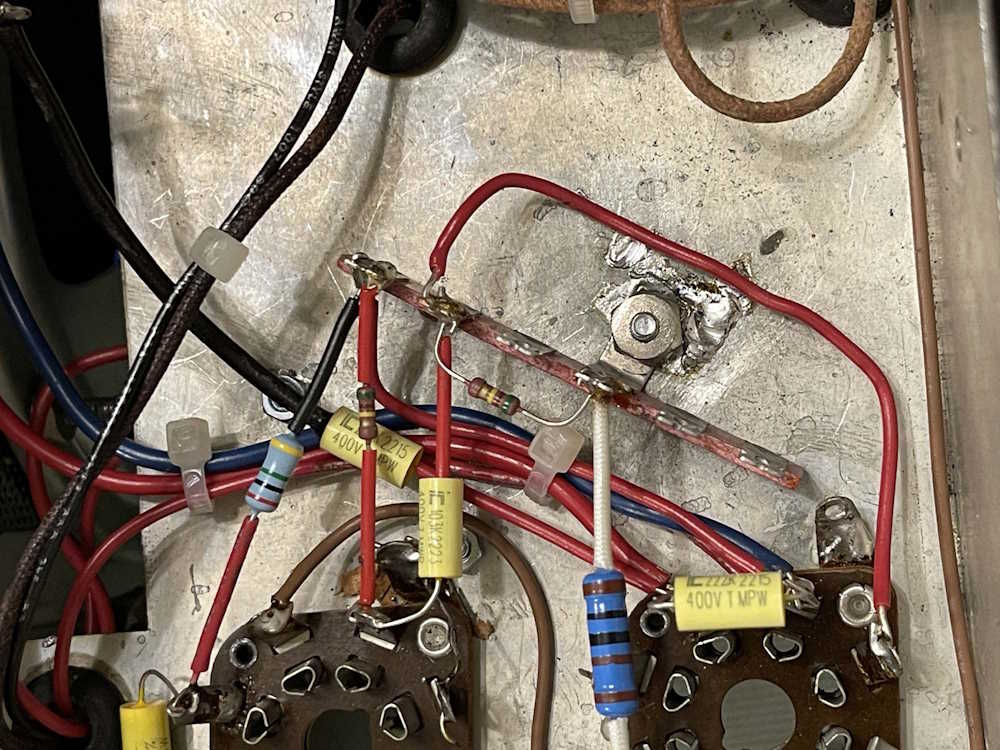
For this last part, I actually used the assembly drawing to put the wires on the switch. Yeah, I know, I RTFM…
There wasn’t much left to do, three wires for the switch and a couple of joints to finish soldering.
Two jumpers on the switch, and one that goes down to the output terminal on the front panel.
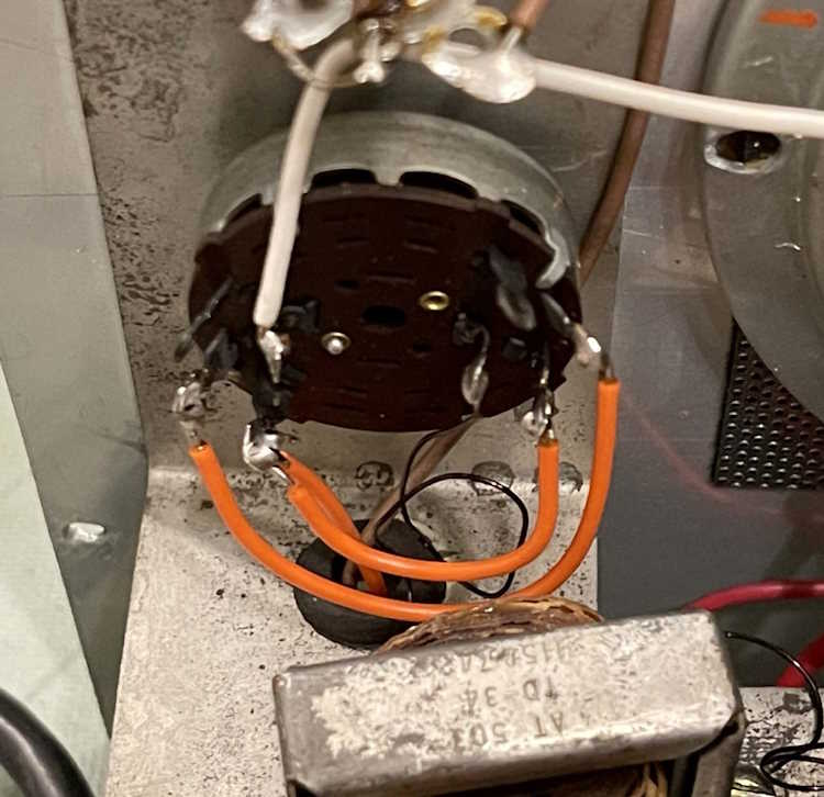
I also decided to hit one of the grounds on the bottom with solder. I removed the bolt from the terminal strip and gave it a quick shine with some scotchbrite, held it in place with an orange stick, and tried to get solder to flow under the tab. Wile it did, I also pooled the solder…the ‘ol 80 watt iron just wasn’t up to the task here. Regardless, I now have a good ground connection here. This was particularly important because this is where the grounds for the amp portion are fed, and I wanted to make sure that no extra resistance was in this circuit - not that it will really matter of course, but the oxides on the chassis may have not given the best ground. Screw went back in, and we’re good to go.
That’s it for the wiring. I tried to follow the schematic exactly, so there shouldn’t be any wiring errors. I hope, but that’s what the next part will be - just tracing things down and making sure it’s all in the right place. I need to get a highlighter or two so I can mark up the schematic.
Only two parts left, and maybe some extra cleanup once I decide what to do with the hole in the front panel. Stay tuned!
Next part of this series: https://wereboar.com … -checking-your-work/
Previous part of this series: https://wereboar.com … art-6d-almost-there/
Wrapup and link to all posts: https://wereboar.com … -and-final-thoughts/