- 2024
- Nov
- 11
A Heathkit IG-72 Signal Generator - Wrapup, set-up, and final thoughts.
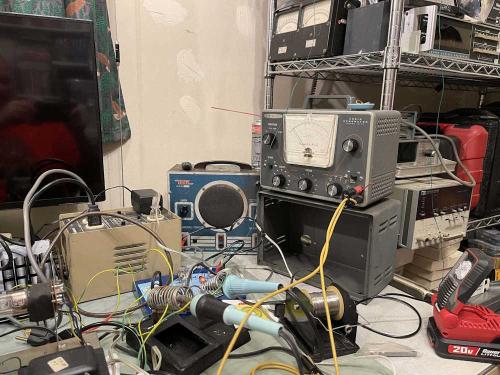
The device is working properly and has been buttoned up and put in it’s home on the bench. Here are my thoughts on how things went…
Thoughts
This unit was really the opposite of everything you expect from an old device. All of the passive components inside, like resistors and capacitors, were in good shape and don’t need replacing yet - although at some point it probably will require electrolytics. That’s for future me to decide.
This device really shows that you have to expect anything with an older device. Parts that don’t do anything other than hold a part can degrade and cause issues, especially when working with the higher voltages present in a vacuum tube device. I never would have though that a tube socket would fail like it did. Sure, they fail because the sockets themselves get weak, corroded, oxidized, etc. and make bad contact, but arcing across? That’s new to me.
I supposed it shouldn’t be unexpected, carbon tracking is a thing. The moral of this story is expect the unexpected. Especially when working with an 60 year old device that was built from a kit.
The complete timeline for this project
Acquisition at the hamfest: https://wereboar.com … o-club-hamfest-2024/
I should fix this thing: https://wereboar.com … 72-signal-generator/
Part 1 - Observations: https://wereboar.com … part-1-observations/
Part 2 - Suspicions: https://wereboar.com … r-part-2-suspicions/
Part 3 - Parts? Parts! https://wereboar.com … t-3-do-i-need-parts/
Part 4 - It’s…fixed? https://wereboar.com … no-need-for-repairs/
Part 5 - We’re not done yet! https://wereboar.com … 5-were-not-done-yet/
Part 6 - Back up and running: https://wereboar.com … back-up-and-running/
Part 7 - I think we’re done: https://wereboar.com … 7-i-think-were-done/
Intermission - The bad part: https://wereboar.com … athkit-ig-72-socket/
Intermission - That odd light bulb: https://wereboar.com … ther-test-equipment/
Wrapup - You’re reading it now.
Notes on calibrating this thing.
The calibration - more of set up - for this device in the manual was written for a time when you probably didn’t have a Hi-Z meter on your bench, but pretty much everything is these days. Instead of following the manual, I did this:
Equipment required:
Oscilloscope
Voltmeter that’s accurate at 1kHz
Leads and stuff
1: Set the frequency to 1kHz, attenuator switch to maximum, and set the output level to ~5VAC RMS using your meter. Ignore the meter on the face of the unit for now. Connect your scope and meter to monitor the output.
2: Let the device warm up. Get it nice and warm. I put a cardboard box over mine to get it toasty. I think this is also how I got it to arc continually so be careful here - don’t set it and forget it. Heat is going to cause marginal things to fail. Check on the device every once in a while during warm-up.
3: After a few hours, when the device is warm, check the sine wave output on your scope. Slowly adjust the oscillator output control (the potentiometer on the inside of the chassis closest to the transformer.) Adjust the sine wave until you just start to get one of the tips cut off, and then back off a decent amount so you have a good sine. Note: These have decent high output with fresh tubes, you can probably back off a lot here. And, I do mean a lot - this will drift so give yourself plenty of headroom.
4: Let it set for a while. You may need to adjust this sine wave a couple of times.
5: When you’re happy with the sine wave, adjust the output level to 5.00VAC RMS with your meter. Using the meter level control on the chassis (it’s the other potentiometer inside the unit,) slowly adjust until the device’s meter so that it agrees with your meter. I use 5V because it’s dead center of the meter’s scale.
You should be able to assemble the device at this point and have a clean sine with a reasonably accurate meter. Note, however that this meter isn’t calibrated at every scale and frequency, so it’s a best guess at all times. The manual even warns about this, so if you need a precise level always let the unit warm up and adjust with an external device connected.
After everything was said and done, I had an accuracy of about 2% with the selected frequency. I think that’s pretty good for a device from the late 50s.
Why did I choose 1kHz? Primarily because this is going to be used for signal tracing. You can choose whatever frequency you think is best for your purposes.
One of the things I’m considering is trying calibration at 10VRMS. That is, set the level control to the maximum, and then back the oscillator control off until there’s 10VAC on the external meter, then adjust the internal meter to follow. This should keep the system well within the linear range. That should be possible since the output is constant before it appears on the attenuator’s input - but there’s always the chance that it won’t oscillate at some point (frequency) because it’s lower than what the circuit is expecting. It’s going to require experimentation to see.
That’s all with this device. It’s been on quite a bit as I’ve used it for testing devices that are in the “keep or sell” pile. If anything else happens to this, I’ll post about it here on wereboar.
Previous part of this series: https://wereboar.com … 7-i-think-were-done/
