- 2024
- Oct
- 31
The 2024 Fort Wayne hamfest
The Fort Wayne hamfest is happening in a couple of weeks. This is a two day event happening November 16th and 17th 2024, and opens at 9AM each day. Admission is $8, and the venue charges a parking fee (this does not go to the show.)
I’ve been to this show many times, it’s all indoors so it doesn’t get snowed out. Prices seem to run average at this one, but there always seems to be a great selection of unusual stuff.
This is the last hamfest I attend for the year, and it makes a nice bookend to the year’s shows.
Fort Wayne Hamfest
Allen Country War Memorial Coliseum
4000 Parnell Ave
Fort Wayne, IN 46805
November 16, 17 2024
Hours vary by day, opens at 9AM
https://www.acarts.com/hfmain.htm
Photos may be delayed a bit due to some obligations the week after, but will be posted as soon as I can get to them.
See you there!
- 2024
- Oct
- 30
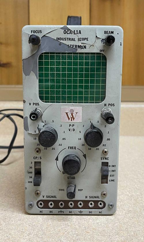
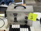
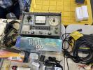
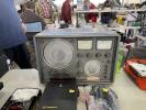
A Waterman OCA-11A “industrial / pocket” oscilloscope.
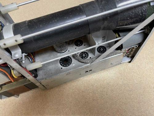
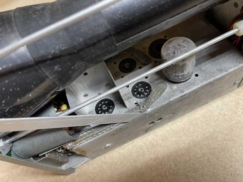
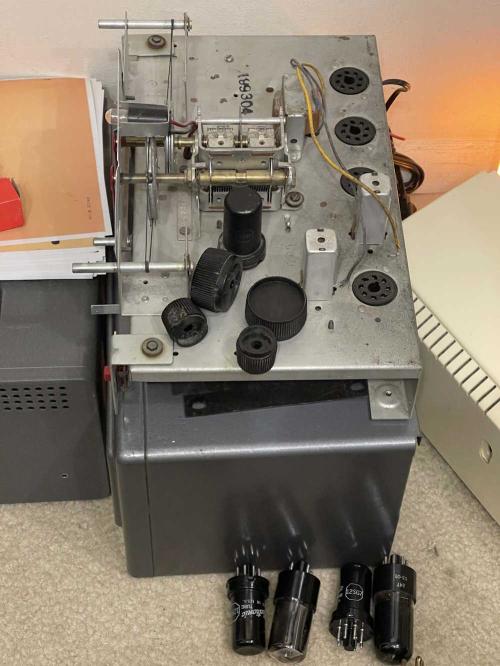
This little scope came from the recent MARC hamfest, and was sold as not working - the previous owner stated that someone had removed tubes, and all he did was verify the heater in the CRT was lighting up. He was right, someone removed all of the 12AX7 tubes as well as a 6U10 compactron, leaving only a 6AG11 compactron in place. All of these devices are triode amplifiers, with the 6AG11 having two diodes in addition to the triodes.
The device appears to have a solid-state power supply with solitary diode. There’s some small evidence of repairs being made over the years, but for the most part it seems to be fairly original.
Tube compliment for this device is:
4x 12AX7 dual triode
1X 6U10 triple triode
1X 6AG11 dual diode/dual triode
The device is capable of operating on 50-400Hz @ 115VAC
The front offers all the controls, and uses pin jacks for input on a strip at the bottom. That’s kind of unusual. The metal under the paint appears to be oxidized, and the enamel with the lettering is flaking off. The potentiometers are brought out to the front by long internal shafts, some of which are bent. This could be an easy fix, as they’re just connected internally with nylon unions.
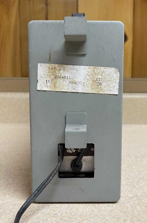
The back offers a cord wrap and some screw terminals, presumably for grounds. It also offers a badly exiting cord from the previous owner.
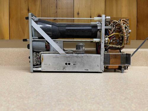
The device is relatively clean inside with the transformer, power supply, and high voltage all riding in the back.
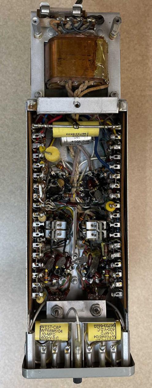
The bottom is well packed, but there’s no wax paper stuff as far as I can see. Looks like films and other decent capacitors, but I bet some of those carbon comp resistors are drifting. There’s an electrolytic that’s probably baked out, and some neon bulbs of unknown type probably being used as regulators that would need to be replaced, but that’s about it.
You can see where the previous owner removed all of the “good” tubes. The 6AG11 is also a triode pair, so I’m not sure why they didn’t remove it as well. Fortunately, if you’re not concerned about the make of the tubes, all of them can be relatively cheap - there’s about $25 worth needed for this device.
It’s an interesting little scope, and would be perfect for a benchtop radio repair station - tube scope with tube inputs doesn’t care if you hit B+ for a second.
I think I may give it a shot and see if it will live again. If someone out there has a schematic for this unit, I’d appreciate a copy.
Next part of this series: https://wereboar.com … oscope-part-2-tubes/
- 2024
- Oct
- 29
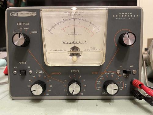
A Heathkit IG-72 Signal Generator Part 5 - We’re not done yet.
I was warming the device up for final cal. I had just completed it, and put it back in the case. Back on and SNAP.
I did some measurements. Nothing much of note. Removed the tubes, applied power. ZZZZZZZ right on the socket for the 6X4 cathode. WTF???
I removed the wire from the cathode to the filter capacitor. Nothing. I reconnected it to the choke. A nice spark was jumping from one of the plates to the cathode. Removed the wire on the cathode and did a measurement from cathode to plate pins.
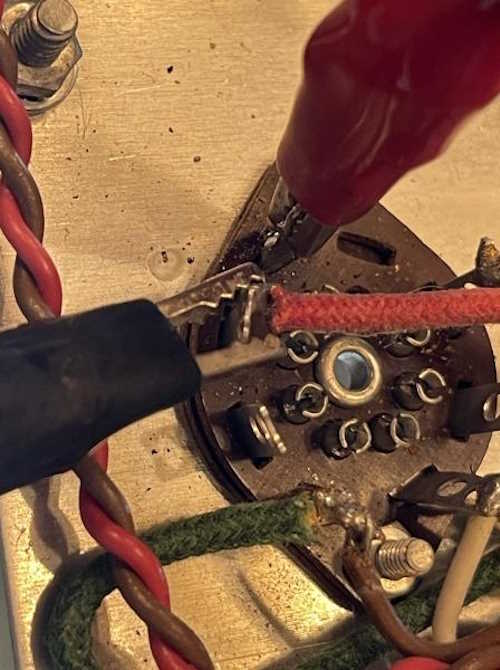
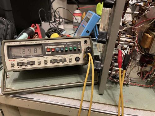
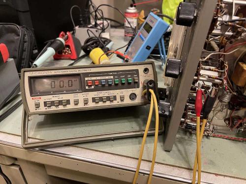
There’s nothing connected to this pin other than my meter. 60Ω is not a good measurement. It came and went as the pin was moved around.
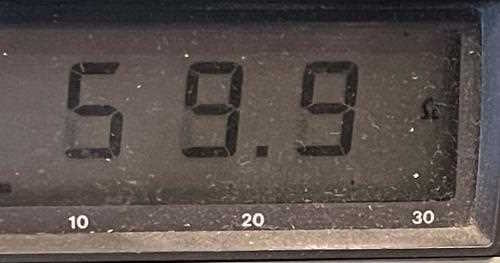
It looks like this double-wafer socket may have some carbon tracking inside of it. Oh fun! That means trying to figure out something to replace it. I have some sockets in stock, we’ll see if there’s one that can be used here.
Of course I don’t have the correct socket - these are 1” mounting centers, which is an oddball size. Most are 7/8”. Off to eBay for the rescue!
Stay tuned!
Next part of this series: https://wereboar.com … back-up-and-running/
Previous part of this series: https://wereboar.com … no-need-for-repairs/
- 2024
- Oct
- 29
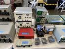
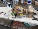
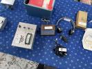
Pictures from the MARC 2024 Hamfest
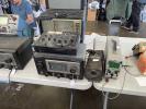
This is a show that I’d never been to, but it was a double treat. The show itself had a decent array of vendors and stuff, and the show was being held at the Military Air Preservation Society hanger, so we were able to tour the grounds as part of our show admission.
I highly suggest you check out the air museum portion, there’s a lot to see. Pictures of that coming soon.
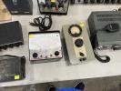
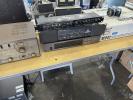
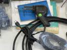
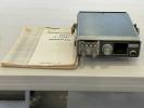
We browsed the aisles for a couple hours, wandering through a few times. I brought home a few books and a small scope, my friend brought home some older high-end audio gear. There were a few other things that caught my eye, but I’ve got enough anchors working right now that I’m good - and the few remaining ones I’d like didn’t show up here.
Regardless, we had a good time and will probably come back next year, time and circumstances permitting.
.
Next (and last hamfest of the year) show is Fort Wayne on the 16th of November. See you there!
- 2024
- Oct
- 29
I hit 1000 views on a post - Thank you!
I keep track of views on my project page - not because I get anything from it, as there’s no ads or monetization (and never will be!) - but because it tells me what people like, and it’s just interesting. Data like this is fun, I don’t know why.
For some time, a post about the Findlay hashtag#hamfest was the most popular thing, but recently a general tech post about not overlooking the power cords on a device during rework has reached the top spot. This morning, it hit 1000 views.
The post: https://wereboar.com … look-the-power-cord/
What does that mean? Not a lot, but I appreciate everyone that’s looked at that post - it means you’re finding things here interesting enough to do a direct click on it, as hitting the post in the feed doesn’t increment the view counter.
Thank you for hanging out and spending some of your time with me. If there’s something you’d like to see more of, I’d love to hear from you. Connect with me on LinkedIn, or catch me on Mastodon.
- 2024
- Oct
- 28
A Heathkit IG-72 Signal Generator Part 4 - Final - No need for repairs.
This is probably one of the easiest devices I’ve had to fix - there was really nothing wrong with it beyond needing a new power cord and a tuneup.
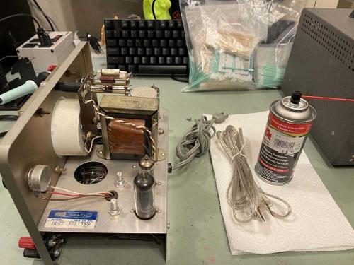
A tuneup, in this case, consisted of some Deoxit in the controls, and a new power cord:
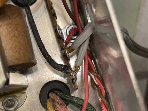
There are three reasons I’m replacing the power cord. First is the fact that the old one is about that close to being hard plastic. Since I have it open, it may as well get a new one. Second, I can replace it with a polarized device. This isn’t a hot-chassis set, but I’d rather have the hot on a switch. Third, this just doesn’t look good to me:
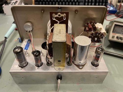
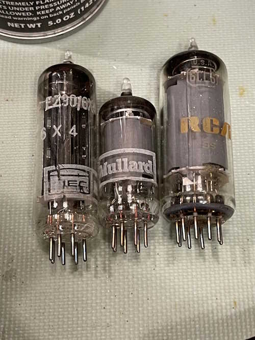
I’m also going to replace the tubes. The old ones aren’t bad, but I bought new ones, just in case. There’s no need to not use them, and the old ones will go in the boxes as spares. I’ll probably pick up another new set, but I can’t imagine these will go bad in my lifetime.
You can also see the new power cord exiting the back of the chassis.
There were two of the original Mullard tubes, and one RCA. The getter flash on the RCA tube looks a little baked compared to the new one, which is a nice, shiny RCA device.
In order to calibrate this, I basically ignored the manual. Since we have DVMs with more than 500 ohms/volt impedance, we can calibrate the device directly. Take note, however, that the device needs to be good and hot before doing this. Let it warm up for a long time to stabilize. I’d suggest taking it out of the case and putting a cardboard box over it. Also note this device was designed to run on 110VAC, so you may need to variac it down a bit.
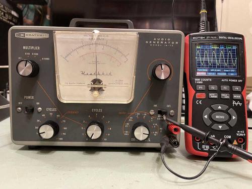
But, to start, I did a quick beginning cal on it. I set the frequency to 1Khz, and attenuators to minimum. A scope was connected, as was a digital meter. Frequency was set to 1KHz, course attenuator (switch) and fine attenuator (pot) to minimum. Meter and Oscillator controls were set to about the middle of their range.
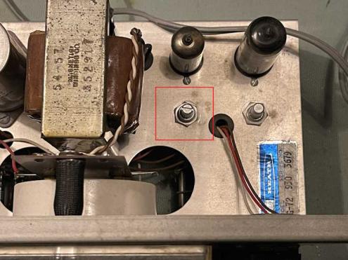
You’re going to adjust the osc and meter controls on the chassis. Oscillator is the one closest to the transformer, and mine had a slot in the top. Meter was closest to the edge, and has no slot on mine.
Power was applied and the tubes warmed up. I turned the course attenuator to maximum, and adjusted fine to about 2/5 of max. The unit wasn’t oscillating well, so I turned the oscillator control CCW until I got a sine. I adjusted this until the bottom wasn’t clipped, and then turned it down a bit more.
For the meter, I adjusted the fine control until my digital meter read ~5.0V, and then adjusted the meter control on the chassis until the analog meter agreed. It’s not a terribly linear meter, so don’t be surprised if it’s off some at other points on the reading.
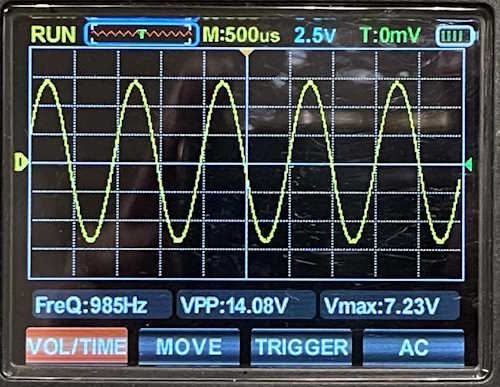
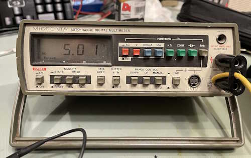
I did notice the signal levels drifted as it warmed up - therefore, let it warm up before adjusting.
I didn’t notice the load switch doing anything. Normally, you would calibrate at load, but I’m not sure why this didn’t do much. I’m not terribly worried about it, the thing makes audio and it’s close enough for what I need to do.
So…that’s it! I’m going to get a box and cover it this weekend while on, let it get nice and hot, and do a calibration - but the device is working with little to no effort.
I have an RF generator to accompany this, I think that may be the next project. Stay tuned!
(Something went wrong during final cal…looks like we do have a problem!)
Next part of this series: https://wereboar.com … 5-were-not-done-yet/
Previous part of this series: https://wereboar.com … t-3-do-i-need-parts/
- 2024
- Oct
- 26
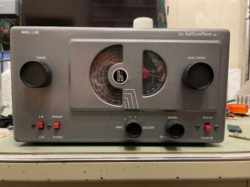
A Hallicrafters S38-C recap.
I picked up this good example of a Hallicrafters S38-C at the 2024 Dayton Hamvention. While it doesn’t look to have had much done to it over the years, it had - of course - bad filters.
In order to remove the old capacitor, a single rivet has to be drilled out. Mine was just below and to the left of the audio output transformer:
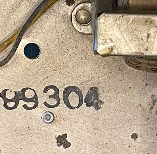
In order to work on the chassis better, I removed it from the case. To do this, you’ll need to do the following:
1: Remove the knobs. These are secured by a 1/16th hex screw. See the warning about the feet below.
2: Remove the feet. These are probably brittle and going to break on you.
3: Unsolder the speaker.
The chassis just pulls out at this point. The paint is pretty thin on these units and will scratch easily. I did so :(
Once you’ve drilled out the rivet, it should allow you to pull the old capacitor off the shaft and pop the remainder of the rivet out. I simply cut the leads on the capacitor to get it out of the way but leave a trace in place for the new parts.
This particular capacitor has 4 sections - 40/40/60/20 - all are 150V except for the 20, which is 50V. All of the sections on mine tested ok for capacitance except the 60. This showed practically nothing.
That doesn’t mean the rest of them were any good, they all showed high ESR and loss.
(Oh boy, did I mess that up! Negatives going the wrong direction…It was…yeah, not enough coffee!)
I kind of did a sloppy job here and I’m not really the happiest with the way they lay, but they’re secure. You’ll notice that there is no 20μF - that’s because some stupid little piggy ordered non-polarized parts instead of regular parts. That’s ok…I need to replace the across-the-line bumblebee as well, so another trip to mouser.com is in order.
This particular bumblebee was coated with some nasty oily substance, but I’m not taking any chances. It gets replaced - even if it was good. I also need new feet for the device, some were worn down and one cracked apart. There’s a supplier for those, so I’ll order some and let you know how it goes.
So…into the waiting room it goes.
Stay tuned!
Next part of this series: https://wereboar.com … ng-back-on-its-feet/
- 2024
- Oct
- 26
A Westinghouse H-636T6 AA5+1 Radio
This is the radio that I picked up at an antique store a few weeks ago. It was pretty obvious that the filters were bad, and the tuning gang was a bit gritty and in need of some cleaning and lube. In order to make this thing play again, the first thing to do was replace the filter capacitors.
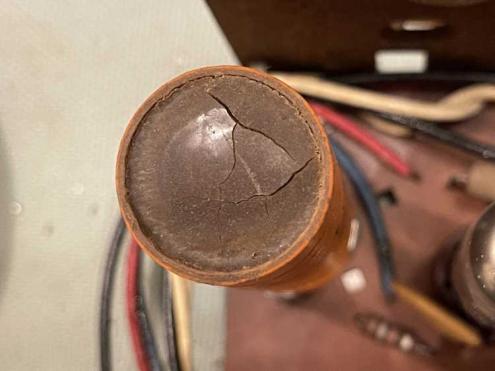
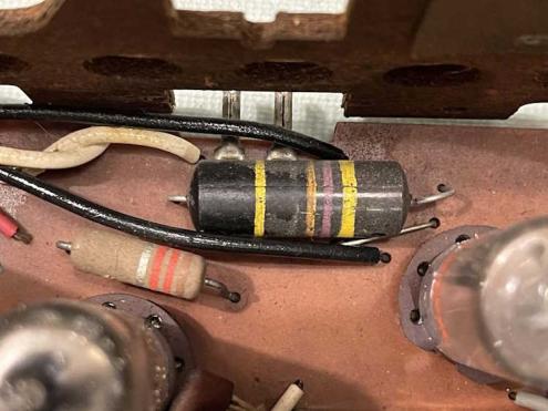
Here’s the capacitor’s top. You can see it’s not in the best of shape.
There’s a lot of cracks in the device. The first thing to do is get the thing out of there.
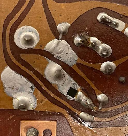
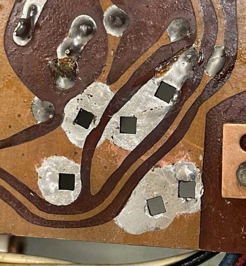
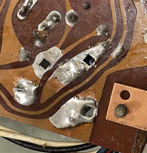
Here’s the spot on the board we’ll be working with. The original capacitor is a 3-leg device where the legs have a crimp that physically anchors it to the board in the square holes shown before being soldered. In this case, there’s enough pad to get solder wick on it. I like to add some fresh solder to get the joint clean and shiny again before wiking it off.
The old solder cleaned up nicely and was removed. Notice there’s multiple holes there, so multiple kinds of parts could be used.
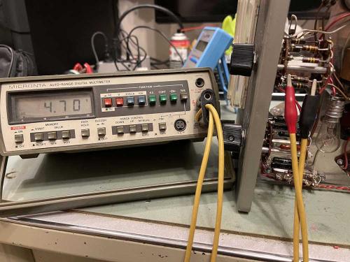
Is the old capacitor actually bad? The doctor says yes:
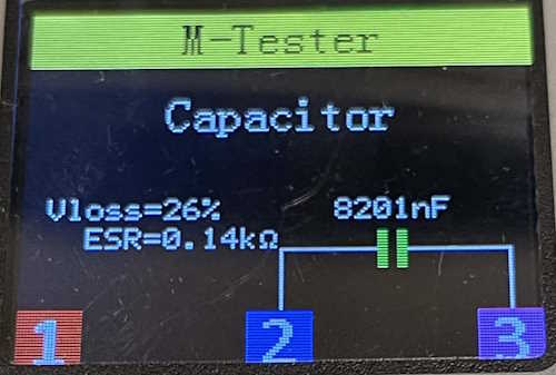
That’s supposed to be a 50μF, not 8μF…not to mention the 26% loss and 140Ω ESR. Is it bad? Yes. Very yes.
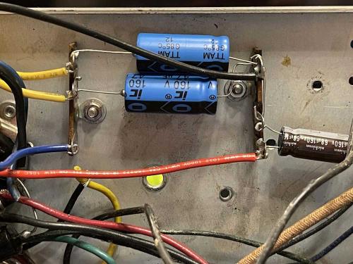
A new capacitor pack was made from two 47μF capacitors. I used some old standoffs rescued from a dead project at a former employer to keep them off the board.
The new leads are much smaller than the old ones, so a lot of solder is needed to fill the pad. Once it cooled, a quick cleanup with some iso alcohol and an orange stick got rid of most of the flux.
Since the plug was clipped into the case (it needs replaced as it’s hard as a rock!) I sliced the old rubber off and pulled it free. I plugged in the radio, tuned it to approximately a station, pulled the knob out and…
WLW, weak but audible greeted me. The first words this thing said in decades was a story about how someone is bombing someone else (again) in the middle East. You could literally be at any point in radio’s history and you’d hear similar.
There’s one last thing this radio needs before the tuning gang gets cleaned and the radio gets an alignment…this part:
Here’s a “Bumblebee” capacitor, or a “bumblebomb” as they’re called. These are a plastic cased capacitor, which tends to crack and leak. This one is directly across the AC line, and it’s going to need replaced. I’m pretty sure I have some suitable replacements here somewhere from another repair. It’s just going to take a minute to find them.
That’s it, that’s really all the device needed to play again - I’m still convinced the seller didn’t know to pull out the knob to turn it on, but that’s not really an issue here. There will probably be a part two later, but there won’t be much to tell on it - just a report on how the alignment went. Stay tuned!
Next part of this series: https://wereboar.com … aa51-radio-it-lives/
Previous part of this series: https://wereboar.com … -westinghouse-radio/
- 2024
- Oct
- 26
A Heathkit IG-72 Signal Generator Part 3 - Do I need parts?
Now that the device is working, the next step is to see what parts are going to need to be replaced in order to make the thing work better.
The short answer is nothing. The capacitors in the filter for the oscillator are on point, the output is close enough that it’s probably not worth changing things, and the filters and electrolytics that connect stages aren’t showing any leakage. That’s pretty amazing for a device this old. I decided to do some checks anyway, just to prove the point.
There’s not much voltage on the resistors in the notch filter. I didn’t check any values, but these are all fairly low so I don’t expect them to have drifted out of tolerance that much.
When the particular part isn’t selected, there’s a little bit of AC on the resistors.
There’s no DC, indicating that capacitors aren’t leaky.
I did some checks on the filters and the other two electrolytics in the circuit - all of them showed a good value with low ESR. At this point, I will probably just check the resistors to make sure they haven’t drifted, and replace those that have. Stay tuned!
Next part of this series: https://wereboar.com … no-need-for-repairs/
Previous part of this series: https://wereboar.com … r-part-2-suspicions/
- 2024
- Oct
- 25
A Heathkit IG-72 Signal Generator Part 2 - Suspicions.
I’ve been studying the schematic for this device - it’s not a complex circuit, so there isn’t much that could be wrong with it:
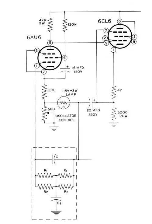
There are two tubes and a lamp used as a PTC that are immediate suspects, as well as the oscillator control. The problem happens on all ranges, so it’s unlikely that any of the filtering circuit is at fault since it’s switched in and out.
The 6CL6 is a cathode follower that provides the input to the 6AU6 so it can oscillate - remember that an oscillator is an amplifier that provides it’s own input. The circuit in the dotted line box is the filter that determines what frequency is being provided. The lamp is used as a positive temperature coefficient resistor that helps balance the signal.
Since the 6CL6 had been replaced in this unit, I started with it. Changing it for a NOS unit made no difference.
The next logical choice was the oscillator control. This regulates the level, not the frequency. The control is outlined in red - the other one is related to meter scaling.
I had the output hooked up to the signal tracer I recently rebuilt, and a noticeable buzz was present. That was the flat spot on the bottom of the signal. With that in mind, I adjusted the oscillator control until the buzz went away, confirming the signal clarity with the scope.
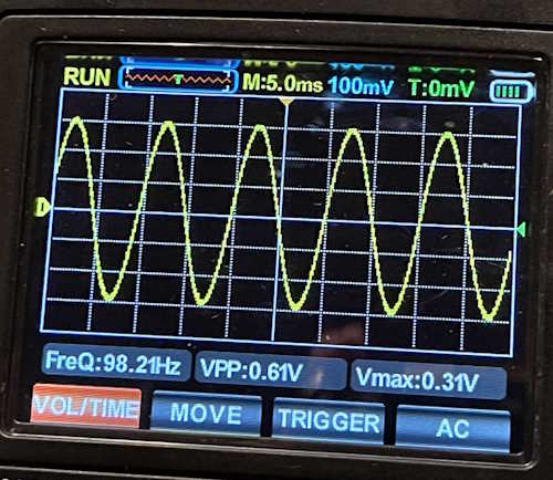
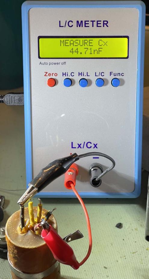
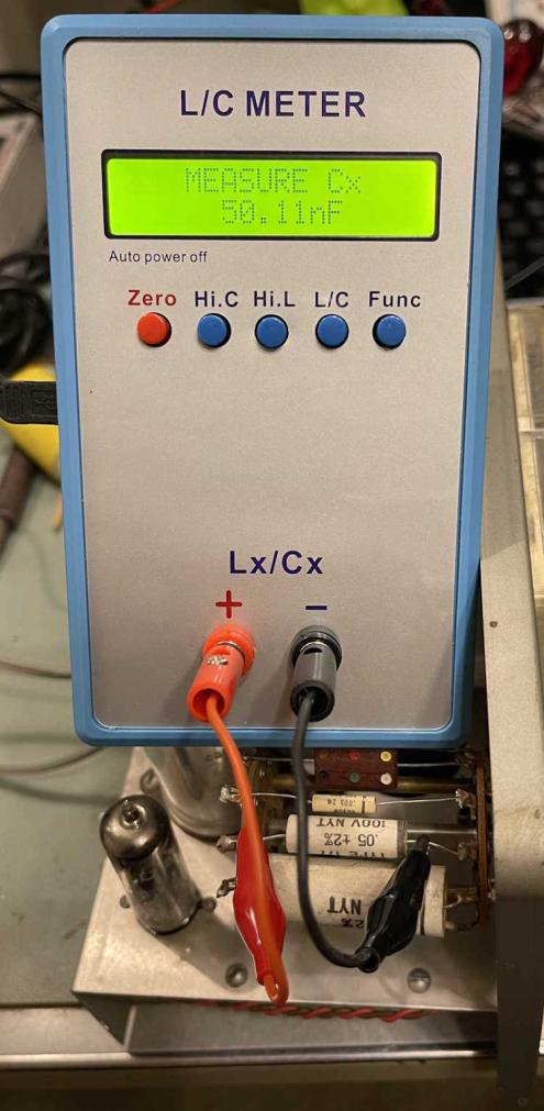
So…the device is working. But that doesn’t mean we’re done. Things like filters and tubes still need to be checked and potentially replaced, and there are some interconnect capacitors that probably should be replaced regardless. I’d also like to tidy up some of those old 5% resistors in the oscillator filter, even though the manual says they probably don’t make much difference. Still…why not. We know carbon comp resistors drift, and modern high-precision parts are cheap. Still, I did a spot check on the capacitors in the oscillator filter:
It’s supposed to be 50nF +/- 1nF. That’s pretty good for a 55 year old part that’s being tested with clipleads. That being said, what’s the leakage and ESR of the part? It will need to be taken out for that to be checked.
Stay tuned!
Next part of this series: https://wereboar.com … t-3-do-i-need-parts/
Previous part of this series: https://wereboar.com … part-1-observations/
