A Simpson 715 AC VTVM Part 4: Filters and WTF?
Tuesday, January 27, 2026 at 13:19:13
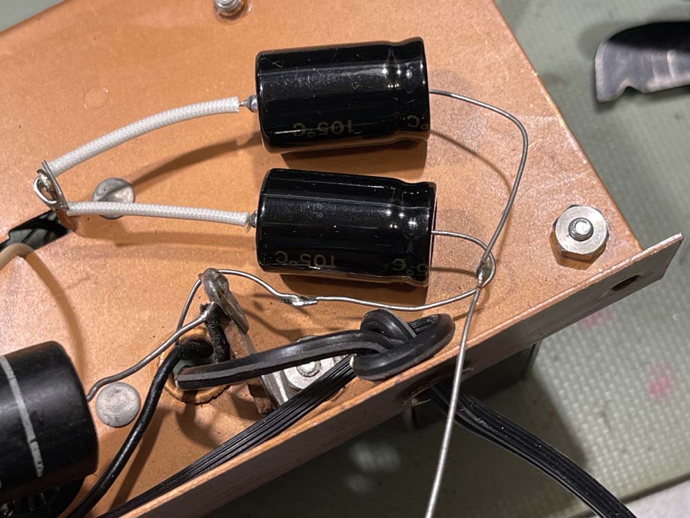
We had a snow day weekend, so I decided to continue replacing the capacitors in the Simpson 715. Today’s subject is the two parts at the top of this stack:

Since the leads on the new ones were much shorter than the old ones, I had to stretch them out a bit by j-hooking the leads and sizing them by pulling to their destination:
Then it was a matter of running some electric sketti on to the leads for protection.
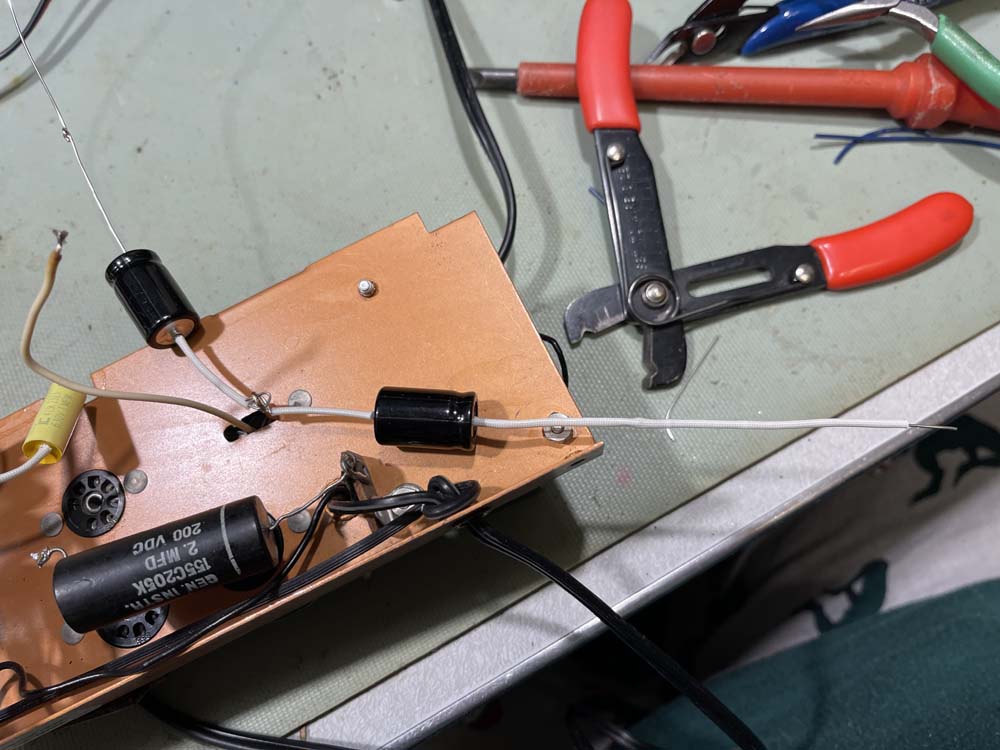
After that, it was just a matter of running them to their destinations. I didn’t solder them down yet because there’s going to be more work to do here in the rectifier section - the lead will need to come off so we can measure draw in order to size the new dropping resistor when the selenium rectifier is replaced.

That lead will need to come out. The other side of the filter pair has been wrapped around it’s post, but not soldered either since the 10k for the second B+ will need to be installed.
When it’s all said and done, the new ones take up a bit more floor space than the old one, but less space overall.

In the meantime, I decided to clean up the meter board by removing the old dry electrolytic and poor soldering. I also prepped the 30Ω resistor that will need to go back on the meter board. The solder came out easily when a little new was added, and all it needs is a bit of alcohol to clean up the flux.
A forum friend suggested that the diodes be checked for leakage before reinstallation, or just replaced. That’s an excellent idea.
The capacitor that came off this board is probably fine. ESR is a little high, but capacitance hasn’t doubled like some of the others.

During the filter install, I noticed something. See this terminal, and that wire wrapped around it?


That lead isn’t soldered. I believe myself to be the first one in here, so that’s been like that since the device was new. This wasn’t a kit device either, even though the construction quality would lead you to believe otherwise. You’ll notice the solder blob at the top is rather poor looking as well.
That wire is a 1kΩ resistor that runs under the chassis. To be fair, it doesn’t look good on the underside either.

That part came out, but was fine:

But was replaced anyway because why not.

The terminal soldered with a bit of flux.

I wonder if this is the problem the meter had, as this is right in the drive line for the meter. If it’s working when I repower, I’ll assume yes because none of the capacitors have been noticeably bad except one.
Stay tuned for the rest!
Next part of this series: https://wereboar.com … -testing-the-repair/
Previous part of this series: https://wereboar.com … acitor-replacements/
Wrapup and final thoughts: https://wereboar.com … -and-final-thoughts/