Early boar ticket prices end March 1st, after that the price goes from $26 to $30. This ticket gets you in for all three days - May 15th, 16th and 17th. Ordering now also gives the post office plenty of time to deliver to you.
If you’d like to comment on a post, please do so - click the link at the bottom of each post that has the word comment in it.
You’ll need a name, and will have to answer a simple question to submit your comment. After that, I’ve set it up so that they are hidden until I can review them - while this won’t stop the spammers, you won’t see it until I make sure it’s not spam. I’ll try and look at any posted comments a couple times a week.
Let me know what you think about the work I’m doing, if you like it (or don’t like it, I’ll take constructive criticism,) or even if you’d like to see more of something I’ve posted. Keep it clean, things that are obviously spam, bait, and profanity won’t be visible.
They’re closed again. Strange Russian spam that I couldn’t figure out what they were posting for, and posts that mention sites that only talk about fans…there’s nothing of use here. Please use mastodon to comment, or join the telegram channels.
There was also the oddity of poor performance shortly after I re-opened the comments, all of which vanished the moment I closed them and removed the links from pages. I have to wonder if someone was slamming the site trying to post comments only to be rejected due to the simple keyword filtering I installed. I’ll know more when I do forensics on the logs.
One of the things that was suggested to me was a quick way to find all of the major projects that have appeared on this blog. The easiest way for me to do this would be as you see it here: a single post, similar to hamfest pictures, that collects all of the major device projects that have appeared here.
This hub contains all the the things I am currently working on, or have completed. New projects that are still underway generally appear at the bottom of the post, and the post will grow as more are added.
There’s a link on the sidebar that will bring you directly to this post.
Click on the title of each item to be taken to that project’s hub.
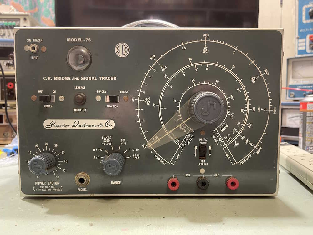
The Superior Instruments Co. Model 76 is an interesting piece, and appears to have been built out of whatever the manufacturer could find at the time. Considering this piece was designed about 10 years after the end of the war, the amount of surplus parts would have been quite high. The schematic that was published and what’s actually in the box don’t match one another.
Here’s what the schematic claims is in the box:
A check of what’s actually in the box:
There’s a lot of different types of components in here. Some RN-type mil-qualified resistors sit beside the cheapest of carbon composite parts. Early ceramic capacitors run with oddball metal can parts, which sit beside devices that have really strange values. The device even uses a low-power RF Triode as it’s rectifier tube.
While this device won’t be difficult to make work again, it’s going to be much easier now that I know what’s inside this thing.
Next part will be getting an order together for parts. Stay tuned!
If you’ve been here before, you’ve probably noticed something different.
There’s a new theme set for the page.
Why? Well - as the world becomes more mobile, the site needs be mobile friendly. While I liked the simplicity of the previous theme, it didn’t react well to mobile and made viewing on your phone difficult. This template is reactive, and shows the site better to both desktop and mobile. I’ll make a few small changes, like the top image, but overall I like this. It’s clean, the colors are calm and pleasing, and it does react well to mobile. I’m still playing with some things, so there’s a few placeholders. I’m also going to try and update Flatpress to a newer version, but that’s going to be in a testing directory - you shouldn’t see any “the way this works” changes until I’m satisfied that the system is operational.
If you’re not seeing a new theme, ctrl+F5 should clear your cache and reload fresh.
I’ve always wanted to have some of the switches in my home addressable by some sort of remote control system. For the longest time, that meant using an X10 device, or some exotic home control units that often times cost a lot and/or required some intensive rewiring that I simply wasn’t willing to undertake.
Enter Shelly devices.
These little modules do pretty much everything I had wanted. They’re small enough to fit into most current electrical boxes (older homes like mine will still require some rework.) They offer power monitoring, as well as local switching capability - that is, you can still use the lightswitch that is currently there. They’re also cheap. Under $20 per, even less if you don’t mind an older generation that doesn’t offer 50 million ways to connect.
These are primarily WiFi devices. The newest generation offers Matter control, but they have a local UI that you can talk to. Shelly provides an application that you can run. Or, you can do as in my case - connect them to Home Assistant, as Shelly devices are a platinum-tier supported system.
To get started, I added the Shelly integration to Home Assistant. I did this some time ago when I was playing with a switch unit, so it was already there for this install. That’s a simple matter of adding it like any other integration within Home Assistant.
First thing I like to do it power them up with a cord I’ve made for this purpose and connect to the WiFi UI on the device. This is a local AP, unprotected, and sits at 192.168.33.1. When powered, you’ll see a new AP with “shelly” in the name. Connect, go to the above address once your device has negotiated everything, and you’re in the UI. I then set the WiFi to connect to my network, rebooted the device, and went back in with the new IP address and disabled the local access point. (Home Assistant will warn you about this if you don’t turn that off.) The Shelly integration then found the devices and automagically added it.
Past that, it was a simple matter of creating dashboard panels and automations like any other device.
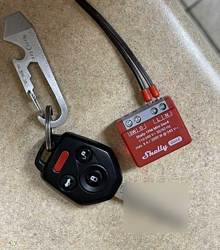
I used two different devices this round:
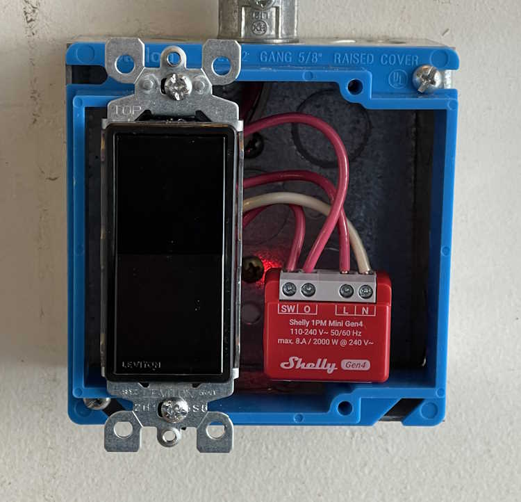
This is called the Shelly 1PM Mini Gen4. (Yeah, they need to work on those names.) It offers both remote switching capability via WIFi, and local switching capability via the “SW” terminal - you simply input the switched line voltage from the original toggle and it takes care of the rest. Other than a slight delay in switching, you notice nothing.
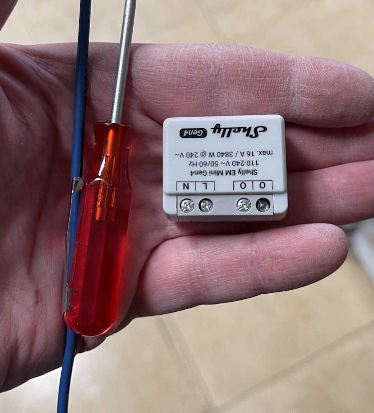
This device is similar, but offers a higher current capacity without any switching capability. I’m installing one of these in an outlet connected to my clothes washer. It connects the same way, just give it power and set up WiFi. The two “O” terminals are the line outputs, you use a single neutral connection which doesn’t pass through so you’ll need to jumper from the neutral line to this device. This is similar for their entire offering.
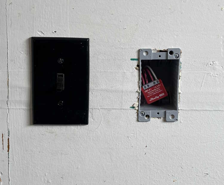
First one is the “Back Porch” lamp. That’s just a wall sconce with a bulb, like any other outdoor lamp you’d have near a door. Boxes in my home are old, small, metal, and cramped. Mounting nails go through the box into the stud, which reduces available space even more.
I decided to mont a new box next to it, just for the Shelly device. Cable was jumped and clamed to the device, and it got covered with a blank plate. Easy in, and can be changed without issue.
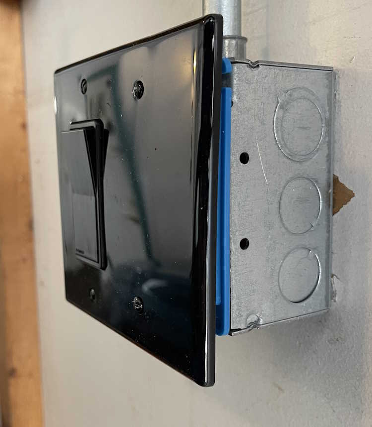
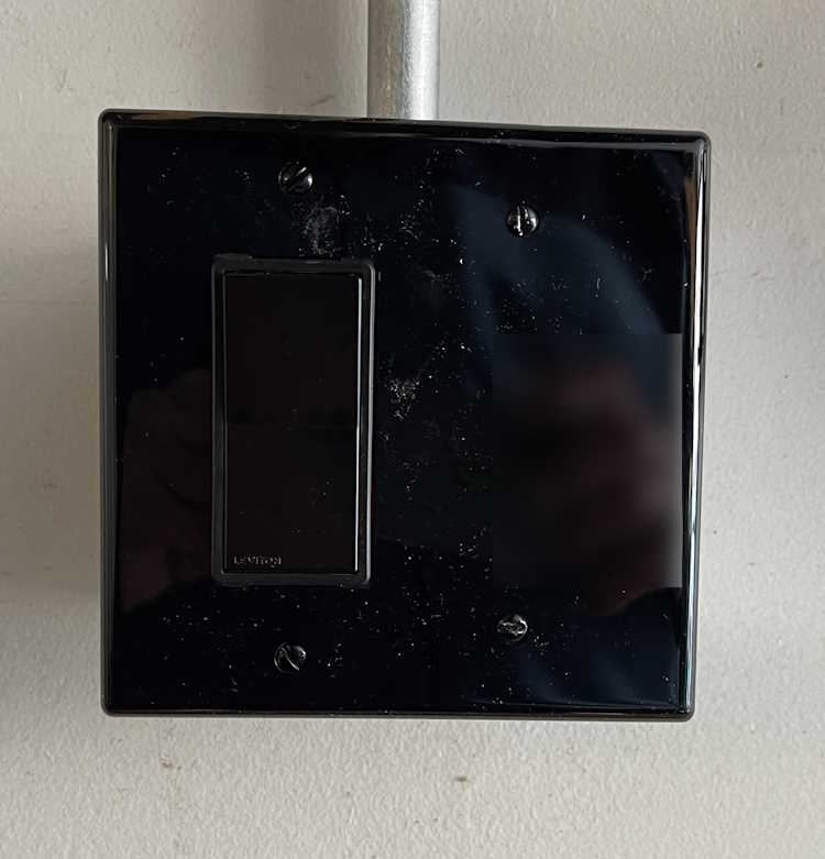
The second PM1 went into a lamp in the garage itself. This is just a wall lamp I put in for some extra light. It’s scheduled to come on and go off at certain times when I have a high probability of being in the garage. This is an on-wall piece of conduit, with a metal box. It originally had a metal plate, so I removed that and replaced with a plastic mud ring and cover. A Decora switch was used because that’s the kind of plate I could get at the time. Like the other unit, this one simply sits to the side of the switch, It faces my local AP, so there’s no signal issue with the metal behind it. You’d never know there was something inside…
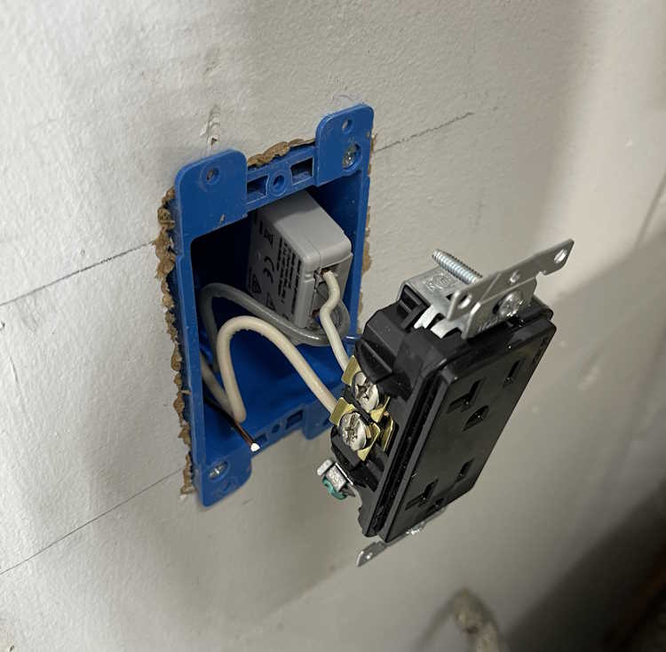
The third one for this install was the monitor-only device for the clothes washer. Again, this was a small metal box, and had a lot of wire in it. I took the opportunity to mount a new box next to it, run some fresh cable, and make the connected in the new box. The EM was attached to the back of the duplex, and simply slides into the box. I left enough cable that this can just pull out if need be, and the device is right there.
The screw terminals on these are just big enough to take a solid 12 AWG wire. Anything larger won’t fit.
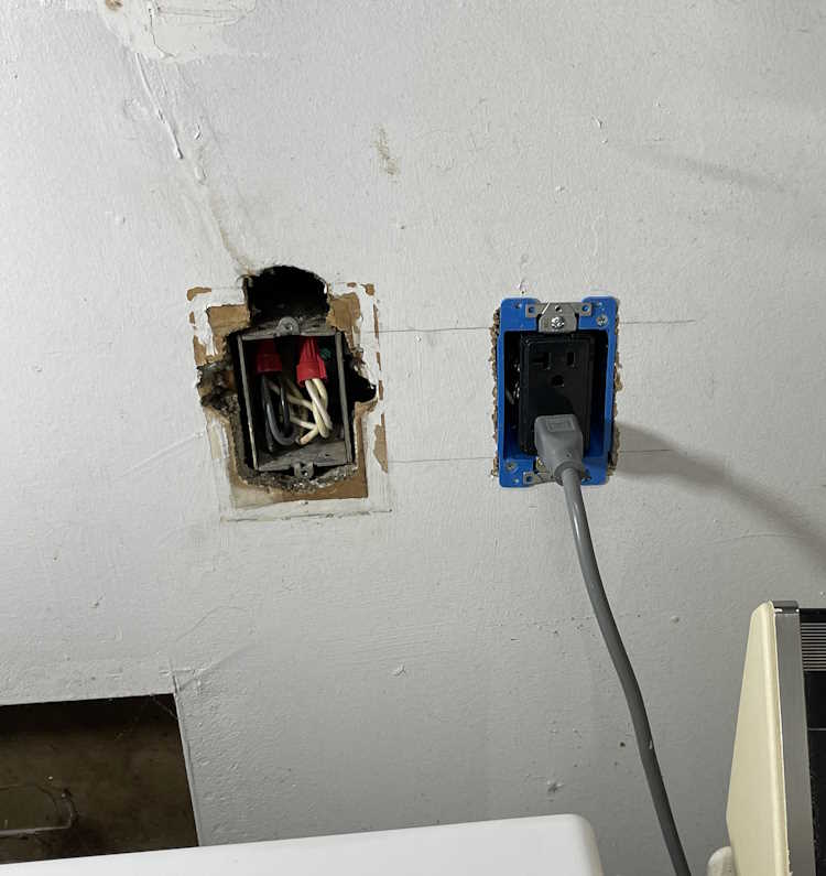
This one looks messy because the previous owner just broke into this box and ran a wire upstairs for an AC unit. You can still see where that was on the wall, and is evidenced by the big hole above the box. This line feeds the washer, and some of the kitchen - fortunately they did pick a 20A circuit, but it wasn’t rated for continuous use + kitchen gadgets. I took the time to tidy up the connection so it wasn’t overly cramped in the box.
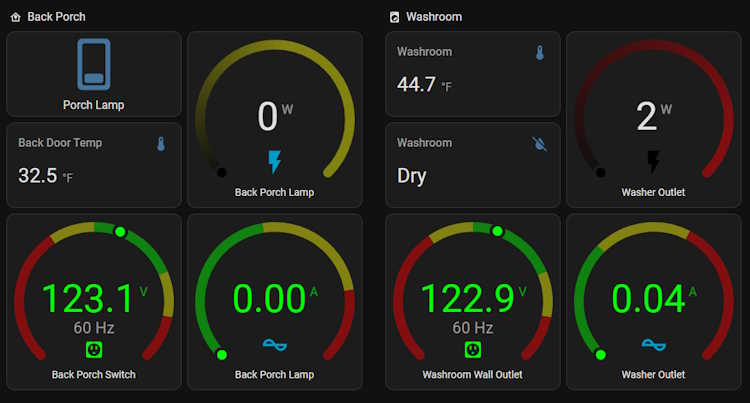
So…what does that look like in Home Assistant? That depends on how you set it up, but this is what I have:
The lights all have switches. The monitor-only just has outputs because there’s nothing to switch. So far, it’s worked quite well and all automations I’ve set up have fired flawlessly.
So what’s the takeaway here? I’d consider these devices to be in the “experienced” category if you have the electrical system in your home that’s able to handle the extra size capacity, or “advanced” if you need to do what I did. They aren’t a beginner thing, but their operation is exactly what you want - quiet, unobtrusive, and full of all kinds of good information.
I’m going to be installing a few more of these devices before I’m finished.
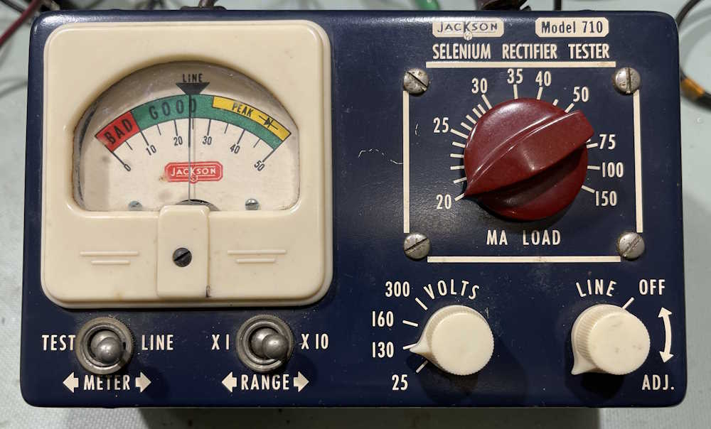
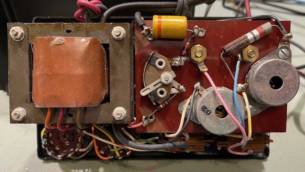
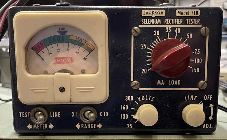
Here’s an odd little device from a different age…this is a Jackson Model 710 Selenium Rectifier Tester. Manufactured by the Jackson Equipment Company of Dayton, Ohio, this is a single-purpose instrument in an attractive case. It was purchased at the Columbus Hamfest for $1.00.
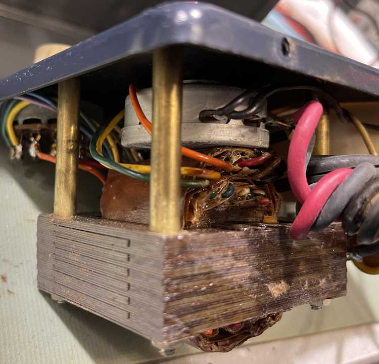
There’s not a whole lot inside of it:
It even has it’s own little selenium stick rectifier at the top.
The business end is the massive multi-tap transformer inside the thing. This is what’s giving it weight.
It also has this cutely named “sele-rater” attached to one of the crumbling leads. I assume this is so you can determine (by physical size) what kind of rectifier you have in your device.
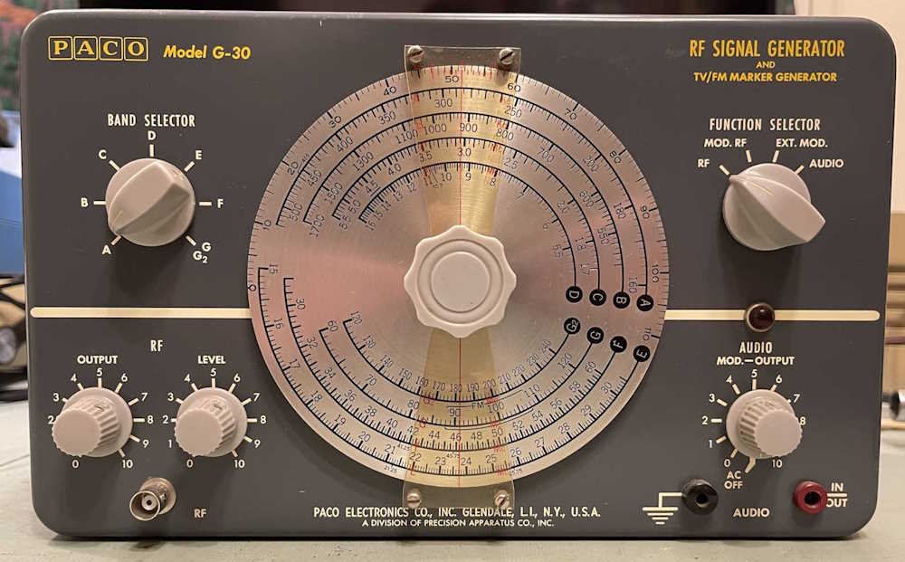
So, does it work? Here’s a selenium rectifier removed from the recent PACO G-30 rebuild. I know it’s still a good device, as it was pulled from a working unit.
Hooking it up and trying every combination of switches I can, I get no deflection on the meter. Ok, so what’s on the outputs of the device?
There’s pretty much nothing on the output, whereas there should be 130V under test. That tells me the selenium stick is probably bad. No surprise.
What’s going to happen to this? Well, it goes back together for now. It’s not a terribly high priority for me as it’s more of a “that’s cool” device. If I can find an appropriate rectifier at a show, I’ll drag it back out and fix it just to make it work. Otherwise, it’s an interesting display piece, and nothing more.
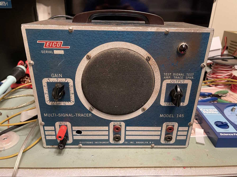
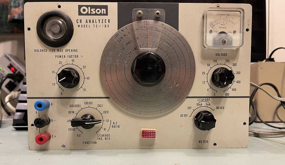
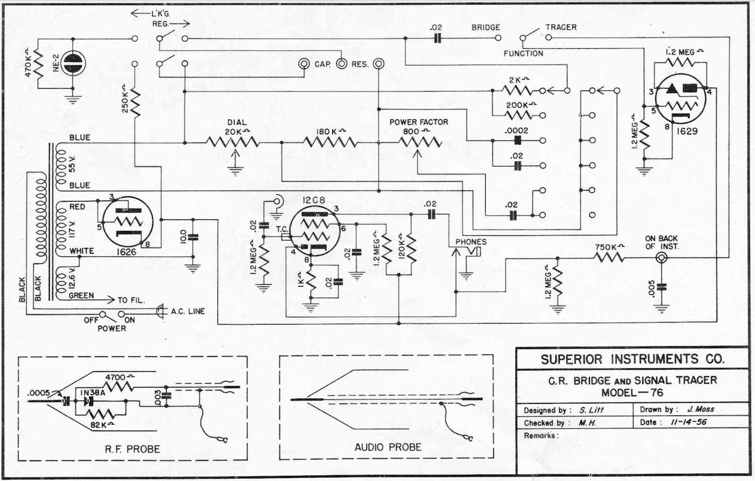
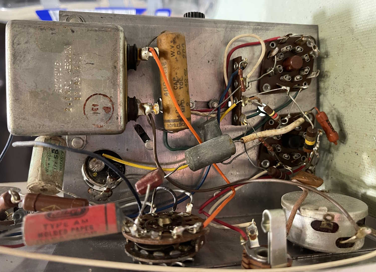
A month or so ago, I made a post about this device, the Superior Instruments Co Model 76 Bridge and Signal Tracer. The unit combines a single tube headphone amplifier for tracing with a bare-bones CR bridge for capacitor testing. You can find that post here: https://wereboar.com … cent-acquisitions-1/ if you’d like to read it.
There’s a lot going on inside of this device. Much of what’s going on inside of this device is of the “What?” variety as the schematic and device itself do not match very well, if at all. The basic components are there, but the actual values and some of what’s there isn’t.
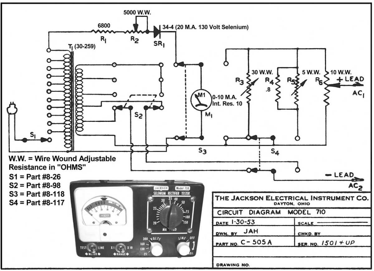
Here’s the device schematic, courtesy of the BAMA archive:
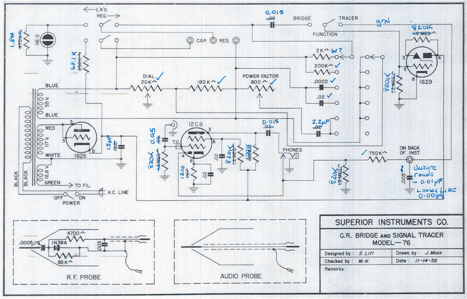
That big motor starter capacitor with the 0.2μF wax-paper across it? On the schematic but listed as 0.02μF . Those two metal cans with no labels in the middle? Not on the schematic…what even are they? They look like capacitors but one measured nothing, the other measured 17μF with a capacitor analyzer. I don’t know that this was available as a kit, so either the OEM just stuck stuff in as needed to solve problems, or someone added these later. I’d go for the “added later” due to the multiple types of sleeving and the fact I’ve seen another one of these that didn’t have those parts.
But there are other things going on in here.
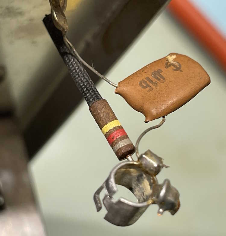
Those are the parts connecting the grid input of the VT153/12C8 tube to the input jack. The schematic states those two parts should be 0.02μF and 1.2MΩ, but instead they are 0.015μF and 820kΩ. Many of the 0.02μF parts in this device are actually 0.015μF ceramics.
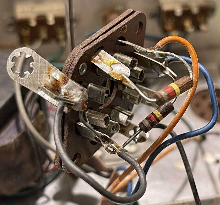
Here’s the eye tube socket. Those resistors are also supposed to be 1.2MΩ but instead are 820kΩ. Like the capacitors in the previous image, many of the 1.2MΩ resistors specified are actually 820kΩ.
It’s obvious this device was built from surplus WWII components. The USN tubes, the RNx resistors, and the oddball parts are all surplus, so it’s no surprise that things don’t match here. However - it’s going to take some doing to rework this item as I can’t simply order things based on the schematic.
The device is working, so there is that. I’m going to work with it a little and try to produce a corrected schematic before proceeding. Stay tuned!
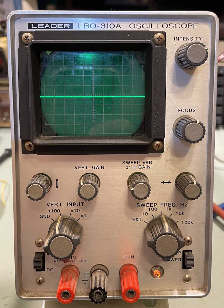
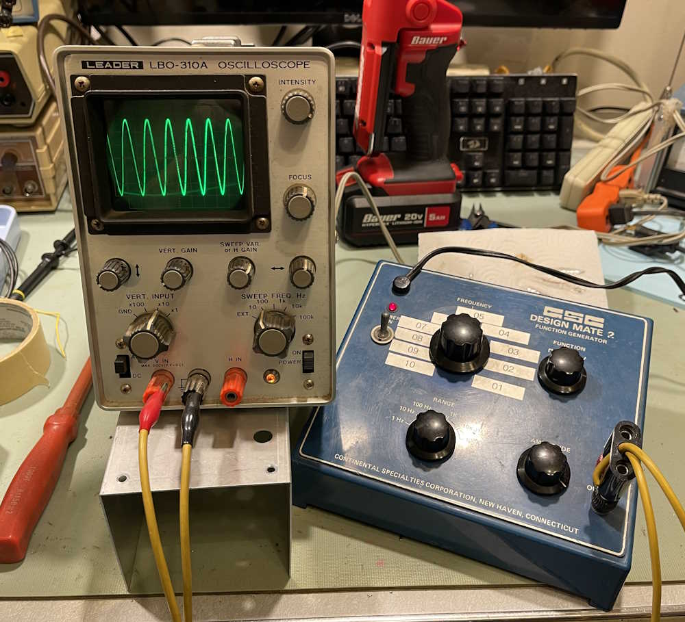
I’ve been unable to find a replacement potentiometer for this device, Leader seems to have used something made just for them. The new parts I purchased won’t fit in the hole in the front, and the knob won’t fit on anything I have on hand…so, I’m just going to replace it as seen in the last post.
A small hole was drilled into the back, and a pot mounted:
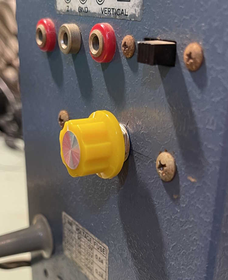
Stick a knob on it. I had … yellow. I need to get a blue one.
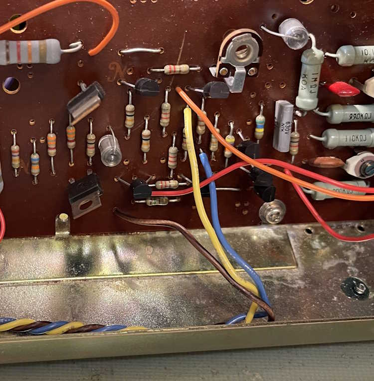
Run the wires to the front, remove the old ones, and solder in new ones.
I didn’t have any green. I thought I did, but the electrons don’t care. Brown was used. If I ever do find an actual replacement, it won’t be much trouble to move the wires back to the front.
The CRT doesn’t have any rotation controls, and the trace is a little lopsided. There are two screws with bands that hold the CRT in place. Those were loosened, the CRT adjusted, and the pot checked for ability. Everything lined up as expected.
It’s still just a hair crooked, but when you tighten the bands it does move a bit. I will probably clean that up at a later date. But for now, everything seems to be acting as expected.
A small CRT scope can be invaluable for audio and low-frequency signals, so this one goes on the bench.
That wraps up this repair. I wish I’d been able to get the actual potentiometer to repair it, but I’m ok with what I did to it. As the show season is approaching, I’ll keep an eye out for potential repair items.
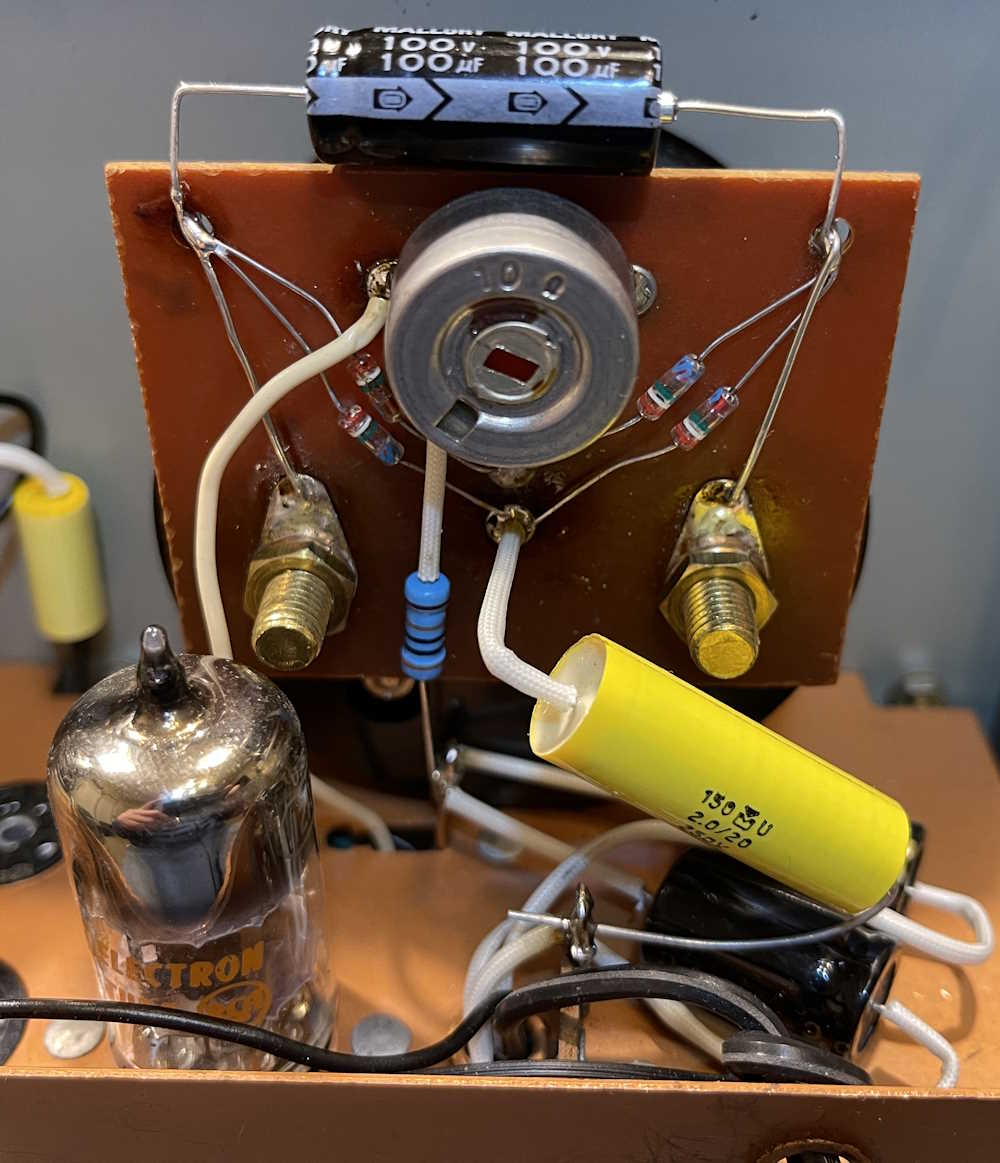
There’s very few parts remaining on the Simpson 715 - mostly just the board that fits on the meter itself. This has a single electrolytic on top, and that connects down to the diodes and then to the meter studs themselves. That was easy enough, the new part is much smaller than the old one and easily fits on top of the board.
That goes back on the meter itself, and a couple of other parts connect to it.
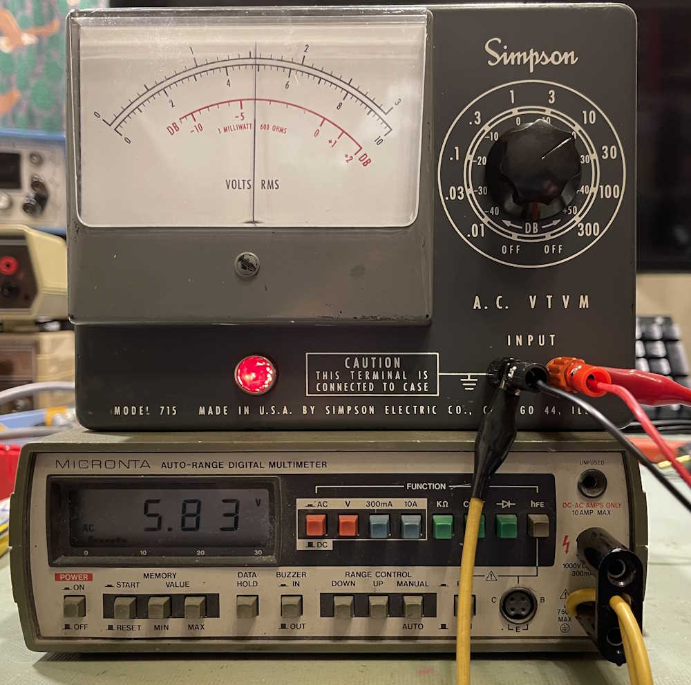
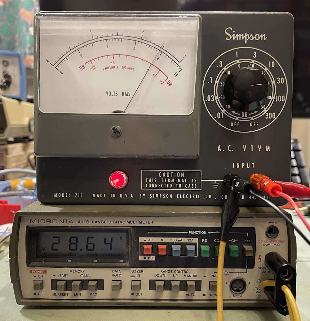
For now, the parts are simply tacked on to their respective tie points, as the meter board will need to come out at some point when the selenium rectifier is replaced. But for now, the meter is ready to test. It does zero now, mostly…it still seems to want to ride just a bit above zero, but it does go to zero, more or less. But there are obviously problems in the divider ladder as evidenced by the readings:
As you go higher the scale, it gets worse. There’s a bad (or some bad) resistor(s) in the divider ladder. That was expected, and wasn’t tested at the start because it was understood that there would be other problems. I wanted to correct the main issue first.
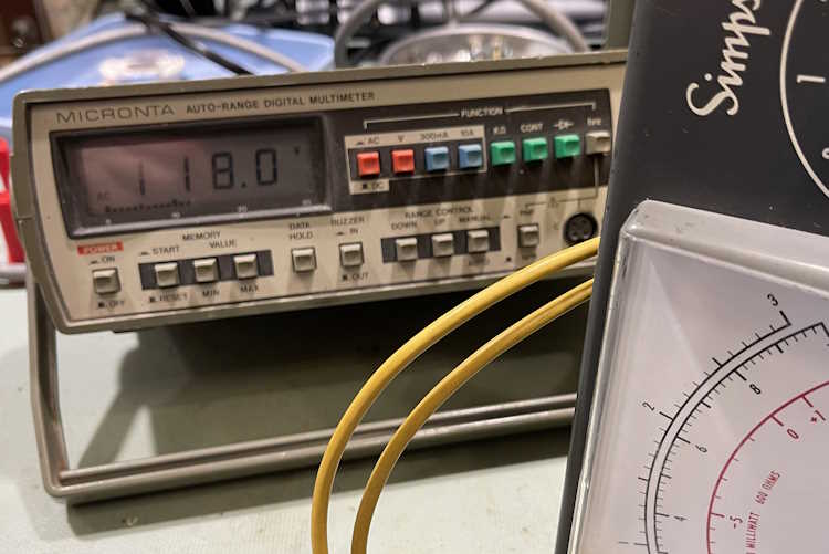
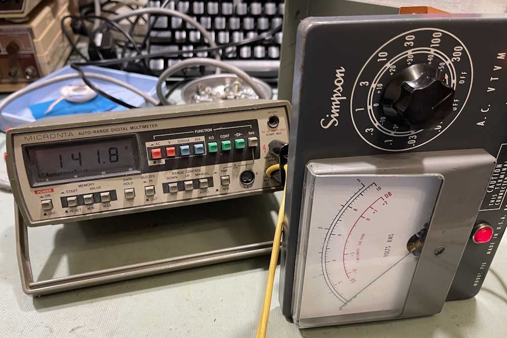
It does work, however, so it’s time to move on to the elephant in the room - the selenium rectifier. In order to replace this with a silicon diode, we need to know the current draw so an appropriately sized dropping resistor can be used in front of the first B+ point. We know that 1mA should be drawn at the second B+ point, so we could probably assume that similar will be drawn from the first B+ point, for a total of 2mA. First thing to do, however, is measure the output on the transformer. It looks like about a 1:1 output, as I have 118VAC on the secondary.
That should give us ~167VDC rectified, since Vr=Vin*1.414 or 167=118*1.414. Approximately.
Since selenium is inefficient, it drops a lot of voltage across it’s junctions, and we actually get ~142VDC. Therefore, the rectifier is dropping about 25VDC.
This is at the first B+ point, which should be 130VDC. The second B+ point should be 120VDC (which is it) with the drop being across a 10kΩ resistor, for 1mA of current. There’s obviously more being drawn here, as there’s still 120V on the second B+ point, so about 2mA of current is being consumed. I’m going to stick with the theory that 1mA should be consumed, so I’ve removed the connecting wire from the first B+ to measure the current in it. I get about 900μA, so we’ll call that 1mA.
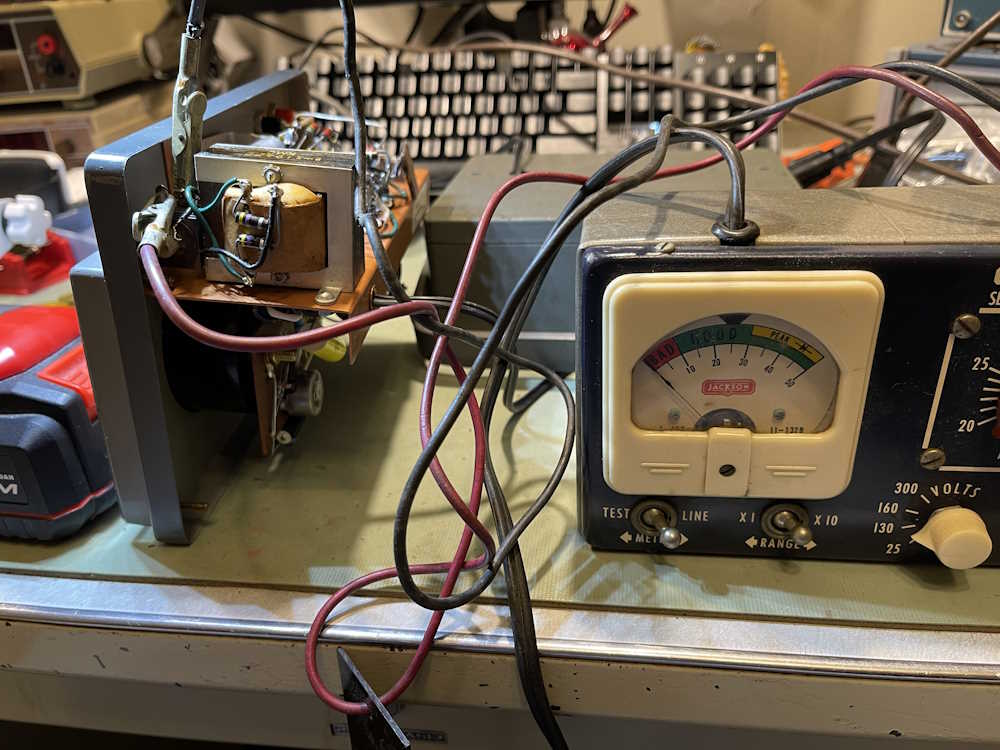
And, the rectifier pops. It doesn’t burn, which is good, but it just quits. Nothing on the output anymore. Well…that’s good that I got to measure what I needed first, but that also gives me a chance to use something I picked up at a hamfest as a curiosity.
This is a Jackson Model 710 Selenium Rectifier Tester. Made by the Jackson Electrical Instrument Co. of Dayton, Ohio, this specific purpose device only tests Selenium devices. It was cheap and I got it for $1, but the only reason I bought it was that it looks cool. However, we get to use it!
The device really needs to have it’s leads replaced as they’re cracked, but it will work for my purposes. I’m not sure what the ratings on the rectifier are, so I set the tester to 130V and 25mA.
Yeah, nothing either way.
I tried every direction and combination of switches I could thing of. No results. Of course, we know it’s bad, but this was just a confirmation of that fact.
I did some work with the tester itself - it’s bad. Post on that coming soon.
That solves the problem of do I actually replace the rectifier, but now I need to get some resistors and check my calculations. This device goes back together and in the queue until I get some parts. Stay tuned!