I recently picked up a big lot of test equipment. There was a unique R-C bridge and this EICO 150, both of which I wanted, as well as a couple of old Leader RF generators and a couple of meters. Other than the first two items, most of the stuff was in really poor condition (foreshadowing!) and was of little interest - or was broken beyond repair.
The EICO 150 was the biggest piece I was interested in, as I have one already and wanted to obtain another for comparison and other purposes.
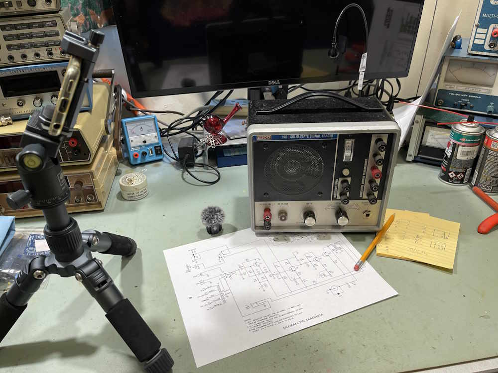
However…as I found out all of this equipment had been modified to extremes over the years. Here’s the front panel:
The trim ring on this, while intact in the original pictures, was completely shattered when it arrived. I tried to claim insurance on it, but the seller just said they couldn’t do it as it was all packed in the box. Well…yes, but there was very little packing material for the equipment itself. This stuff was shipped by airline, and got tossed around. All of this stuff was knocked about and this piece in particular was quite smashed.
Fortunately, a friend was able to model a trim ring, and we’re waiting on some gray filament to make a test print. Stay tuned on that one, I’ll post the files as soon as I have them and we’re happy with the quality.
The back was in ok shape, one of the cord mounts was bent. This looks to be a chassis problem and can be knocked back into shape. The cordset, however, is a mess and will need to be replaced.
Inside, it’s even worse. I could see there were some changes made just by peeking in the hole left by the ring. But to what extent, I have no idea.
That’s certainly not the OEM amp board. It’s also not the OEM power supply. Everything has been modified. The underside has a bridge rectifier power supply with a few parts just floating in the air. Did they come off their terrible joints, or were they placed like that? I have no idea.
That’s the amplifier board. It’s using an AN214, an old-school power amp from Panasonic. This one has the Matsushita triangle on it, and of course Panasonic was one of their imprints. It commonly showed up in low-power consumer electronics, and is usually rated around 4W. This board probably came out of such a device, but who knows. It’s obviously pretty old.
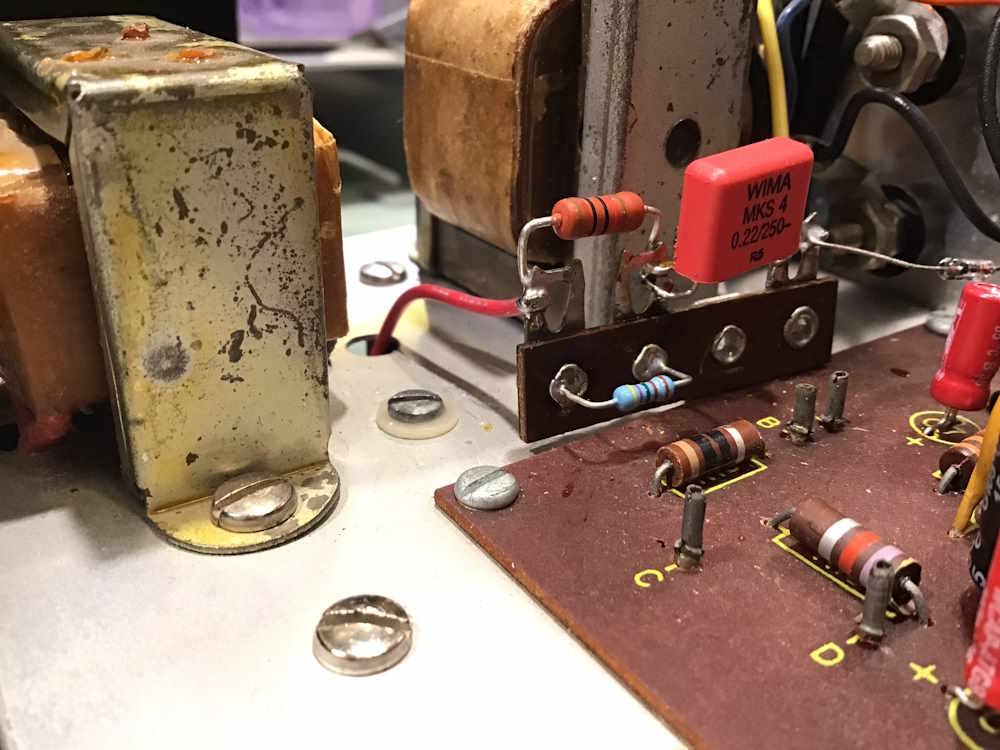
That’s not supposed to be there. It’s an across-the-line capacitor and looks to have come from an old radio or television of the 1960s. Soldering is poor to terrible on all of these connections.
Pretty much all of the switches have been cleaned of their connections.
The meter drive is similarly messy.
Even the power transformer has been changed out. If the label on the top is correct, it says 15V 1A, which is much less than the higher voltage unit originally present.
So…the million dollar question. Does this thing actually work?
Yes. It does, and is actually very quiet - i.e. no noise. This amp board is quite well made.
I want to make this thing work properly, so it’s going on the bench at some point. There’s a lot of cleanup, and I may lay out a board for it, just to see what I can do.
I’ve added some new documents to the library, and I’m going to try and create a new zip every quarter (or so.)
This archive contains all of the documents I’ve collected for projects - at least ones that I can share. This is currently about 400MB, and is a zipped archive of zipped files of many different kinds.
Note the Drive link provides you a .7z file with a simple password: 123456 - this is to keep a certain website from complaining that oh no there’s words in that document I recognize and you can’t do that!
We weren’t sure what the day was going to bring, it looked decent but was promising rain later.
While the rain did hold off, it started raining shortly after we left. Later that afternoon, it became dangerous, including a tornado touchdown somewhat north of the area. This was followed by torrential rains, and then a lovely cool evening.
There was some good stuff at the show this year, with more of the kinds of things I go for than I saw at Dayton this year. I picked up more at this show, things I can actually use (and one project) so it was a pretty decent show. In all, I think the threat of rain kept some away, but there was a good turnout nontheless.
here’s what i saw at the show:
An ignoble end to the Bell System.
Some Atwater-Kent goodies.
Right off the boat from Hong Kong.
One of Heathkit's FM Deviation Meters. It was rough inside.
A rather unusual piece of Heathkit equipment.
A wonderful example of a “Majestic” style console.
I can't remember what house brand this was.
I took this one home.
I also took this one home.
A nice Heathkit bench supply w/manual.
I took some banana plugs (not shown) home.
Some cool old RCA component trays.
A slide rule S-38.
One of the few boombox devices I saw.
More rat shack stuff.
Boom? Boom.
Some waveguide bits n bobs.
The Heathkit Distortion Analyzer came home with me, I have a better chance of getting this one operational than the EICO unit i had earlier (Later me says it works, and seems to work quite well!) Stay tuned, that one will show up on the bench at some point. I also brought home the Heathkit supply, as well as both of those Radio Shack benchtop meters. There were a few parts in there as well, in all it was a good show for me.
Next show is Columbus, Ohio at the Shriners Temple on August 1st. See you there!
This isn’t a comprehensive test, it’s just a “does it work?” thing. And it does.
The kit assembled quite easily, but you should definitely pull a schematic from the vendor’s site because there’s no indications of values on the board.
I did have two issues with assembly, both of them my fault:
1: I put a capacitor in backwards, took it out, put it back in the same way, and destroyed a pad in the process of removing and replacing it once more.
2: I started to install a resistor in the wrong place because I took the part identifier to be pointing to an area it wasn’t.
Neither of these is the vendor’s fault, and I blame my not stopping for a break for the first one. Always take breaks when building something like this.
But, the kit turned out ok:
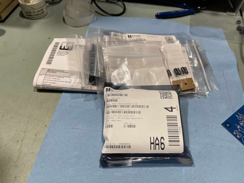
Parts were purchased from mouser, with some (the screw terminals) coming from my own stock. As the BOM the vendor provides has a lot of obsolete parts, I created a new one:
Note this does not include the screw terminals, which I had in stock. See the references section for this as a text document and for the schematic. Both are available in the wereboar documents library.
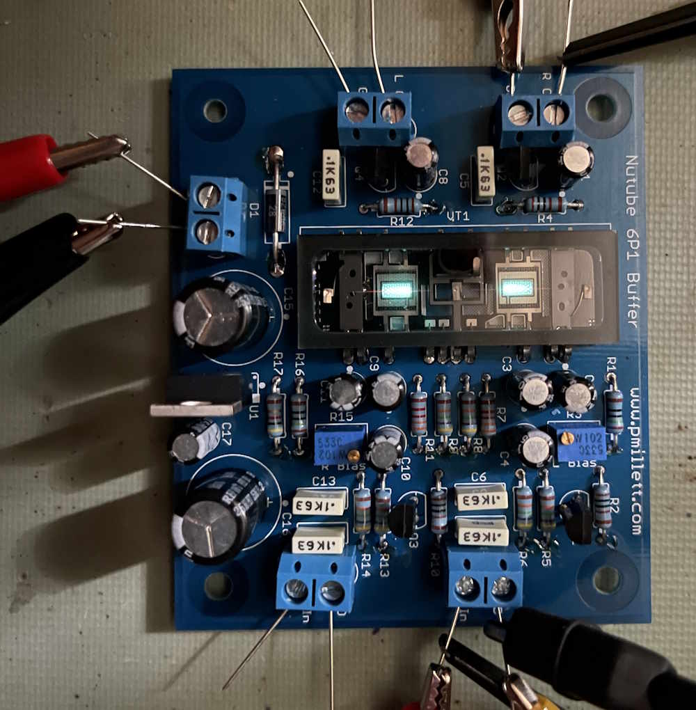
I’m using 12V from my bench supply to power it:
It seems to be drawing about 62mA.
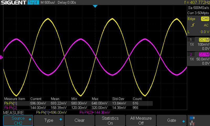
Signal output is, of course, inverted from the input because that’s how amplifiers work. Here’s the output (yellow) vs. input (magenta):
Gain in this configuration is ~4. A bit more than a buffer, but fine for low-level signals.
It works, and there were no real issues with assembly. What am I going to do with it? No idea. It may end up as just a small signal amp on the bench, I’m not really sure. Stay tuned!
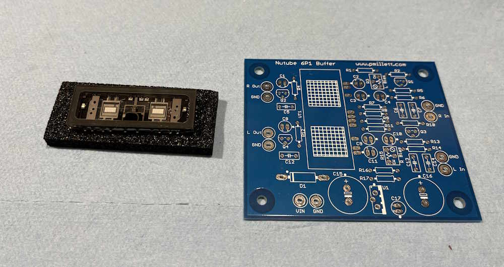
I’ve known about these devices since they were introduced a decade ago, but never really had access to one. I decided to get one to see how it works. There’s a seller on eBay that has both the tube and a PCB for a buffer amp, and I decided to pick one of those up. Here’s the good stuff:
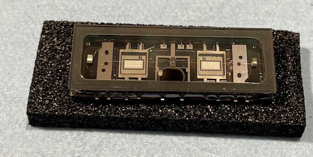
The device itself is kind of interesting - if you said that it looks like a vacuum-fluorescent display, you’d be correct. That’s exactly what it is.
What is this, exactly?
A vacuum-fluorescent display, or VFD, is a type of display that uses a filament, grid, and plate - just like a normal tube. The plate in this case is a painted substrate that is flooded with electrons, and this flood is either allowed or prohibited due to the charge on the grid. It’s and on-off device, but it still fulfils the basic requirements of a triode tube.
The Nutube takes that idea one step further. Instead of a painted substrate that’s a numeral or symbol, the plate on this one is just that - a rectangular plate that is flooded with electrons from a filament, modulated with a grid in the middle. It does glow in operation, but that’s not the point - this is a flat-pack tube that can amplify audio. It was designed, AFAIK, for Korg’s musical instruments because “tubes!” and because this device doesn’t need the high voltages that something like a regular 12Ax7 device would need - even though those higher voltages are trivially easy to generate these days.
The tube’s numbering doesn’t really follow standard conventions, but whatever.
The vendor provides a BOM for this device’s board, but it’s out of date. I’ve created a new one and will post it as I build this device. In the meantime, I’ve ordered parts and hopefully will have time to assemble this device in the next few weeks:
Stay tuned for an updated BOM and assembly thoughts.
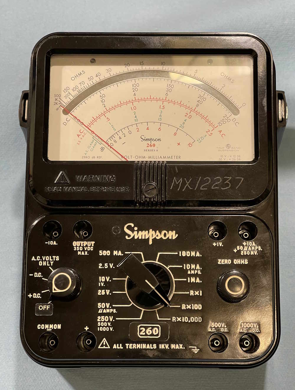
I had a request in regards to a Simpson 260 multimeter. I was asked if I knew what the handle bolt sizes are - I do not, but I decided to take a quick look to determine if there was anything of use easily visible. I have a series 8 available, so I said I’d take a look.
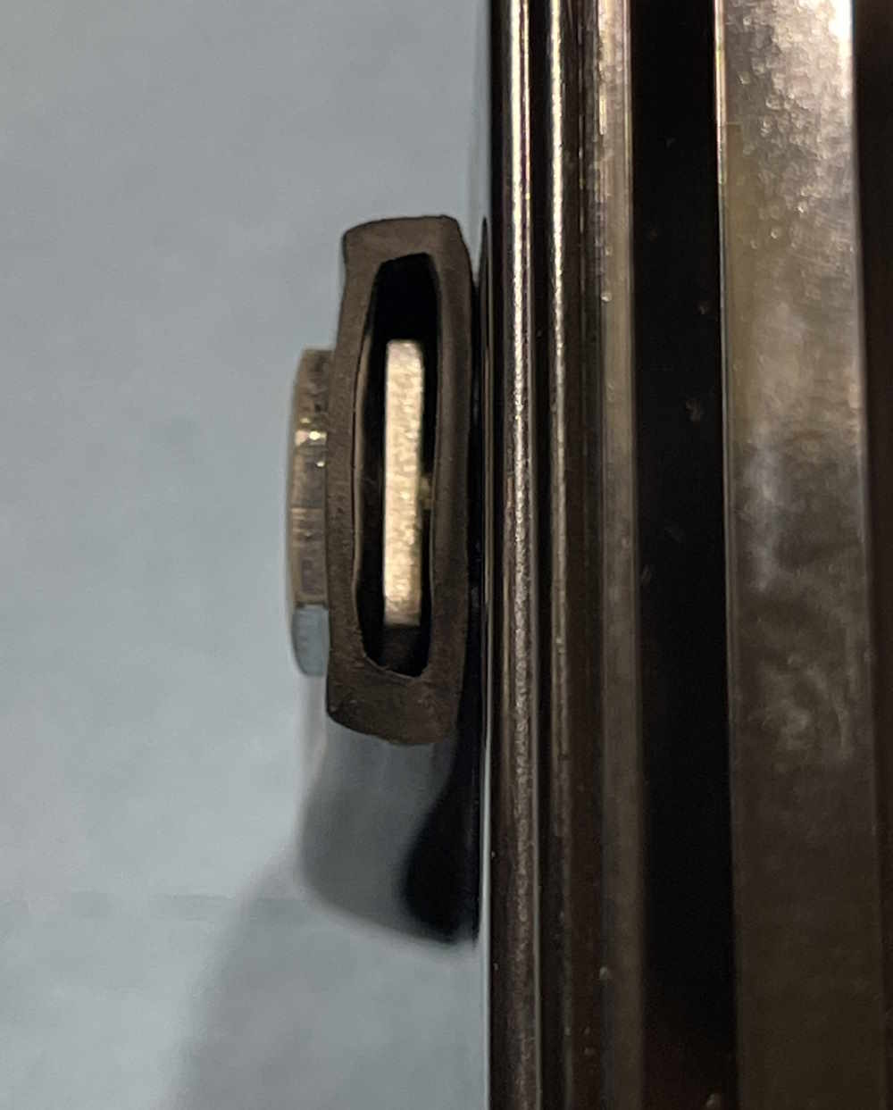
The first thing of interest is the handle itself. The handle is held on by two large hex bolts with a thin head. These bolts pass through the handle. Inside the handle itself is a piece of metal. This metal pivots with the handle, but doesn’t necessarily appear to be part of the handle.
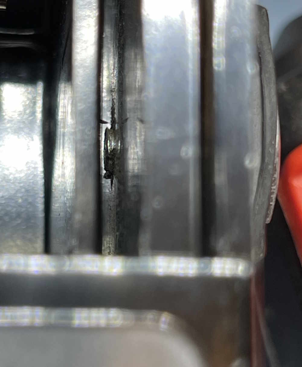
The bolt then passes on through the case.
Unfortunately, I can’t get this apart to measure the end of that, I suspect these have to come out before the meter assembly pulls from the case back.
That’s all - this was just a check of some parts on the unit. Stay tuned, more good junk on the way!
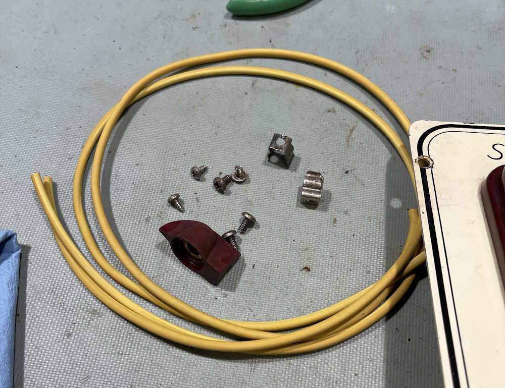
This device was an easy fix. Some wire, a couple of probes, some grommets - and we’re done. Cable is even color-matched to the unit!
I scrubbed the case down, and gave the switch a spray of Deoxit as a preventative, even though whatever the OEM used was not really tarnished like other switch rings I’ve seen.
So. Does it work?
Sure does! The new battery reads as a new battery.
That’s all for this device, it goes on display until needed. Stay tuned for more EICO 950A goodness!
Working with this unit has been interesting, especially with the original problem of being a shorted speaker. But, for now at least, the unit is operational but still has some issues to solve later on.
What’s going on?
After the speaker replacement, there was simply a lot of noise. half a volt of noise, to be exact. This was unacceptable, and there were two potential causes - the transistors, which most say to replace with the capacitors, or the carbon composite resistors.
The transistors helped considerably, but only Q3 and Q4 - this reduced the noise levels to about 1/4 of the original, as received value. That’s pretty good, Q4 was noisy and replacing it with a (not really much newer) transistor cleaned that up. The rest, unfortunately, it probably coming from resistors and I’ve read posts indicating that metal film resistors here help considerably. That will be another project later in the year.
Beyond that, I changed the meter drive level. The meter on the front is simply a mechanical version of an eye tube. That is, it’s not calibrated in any way, it’s just deflection. You really had to drive the thing hard to make it move, and I wanted that to happen at a lower input. Paralleling a resistor with the input resistor has allowed that to happen, and it’s placed as such it’s going to be easy to remove should I or a future owner want to bring it back to spec.
Anything else?
There’s nothing to say other than to pay attention to your replacement transistors. Leads aren’t always the same from part to part!
In the last part of this series, I put some new transistors in the device. And had to replace them once again because they were inserted incorrectly.
With that being fixed, it’s now time to check the unit for actual operation, make one final mod, and see what we have. Here’s the data:
What the manual says:
What the old transistors said:
What the new transistors said:
And finally, the noise levels:
The noise is very similar to what we saw after Q3/Q4 replacement, so the previous transistors, while providing the noise, don’t seem to be causing it. Some commentors on the youtube videos suggested the resistors are probably doing it, and I tend to agree. Old carbons are noisy.
The transistors also show some improvement in voltages, especially Q1 and Q4. Q1 should be off when measured in this configuration, and it is. Q4 is now closer to the Vdd rail, as it should be. Current draw on Q4 has also reduced, but is still high - probably because it’s amplifying noise. We’ll see what resistor levels do to that.
The final piece is to change the meter level. You really have to drive this thing hard to make it deflect, and I don’t want that. Calculations made during a forthcoming video suggested something around 3.1kΩ would make the meter happy. I accomplished this by paralleling a resistor with the 10kΩ input, and that resistor turned out to be around 4.7kΩ. It was stuck into the holes in the terminal strip so a future owner can easily remove if needed.
With that, this project is finished. I’ll probably start a new one later to swap out those old carbon resistors - but for now, that’s all and the device is working well. There’s one more post for the wrapup, and please check out the YouTube playlist for this device.
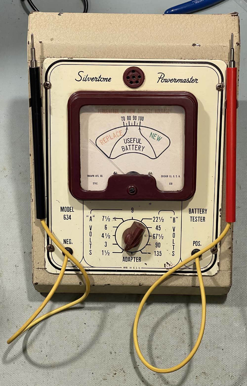
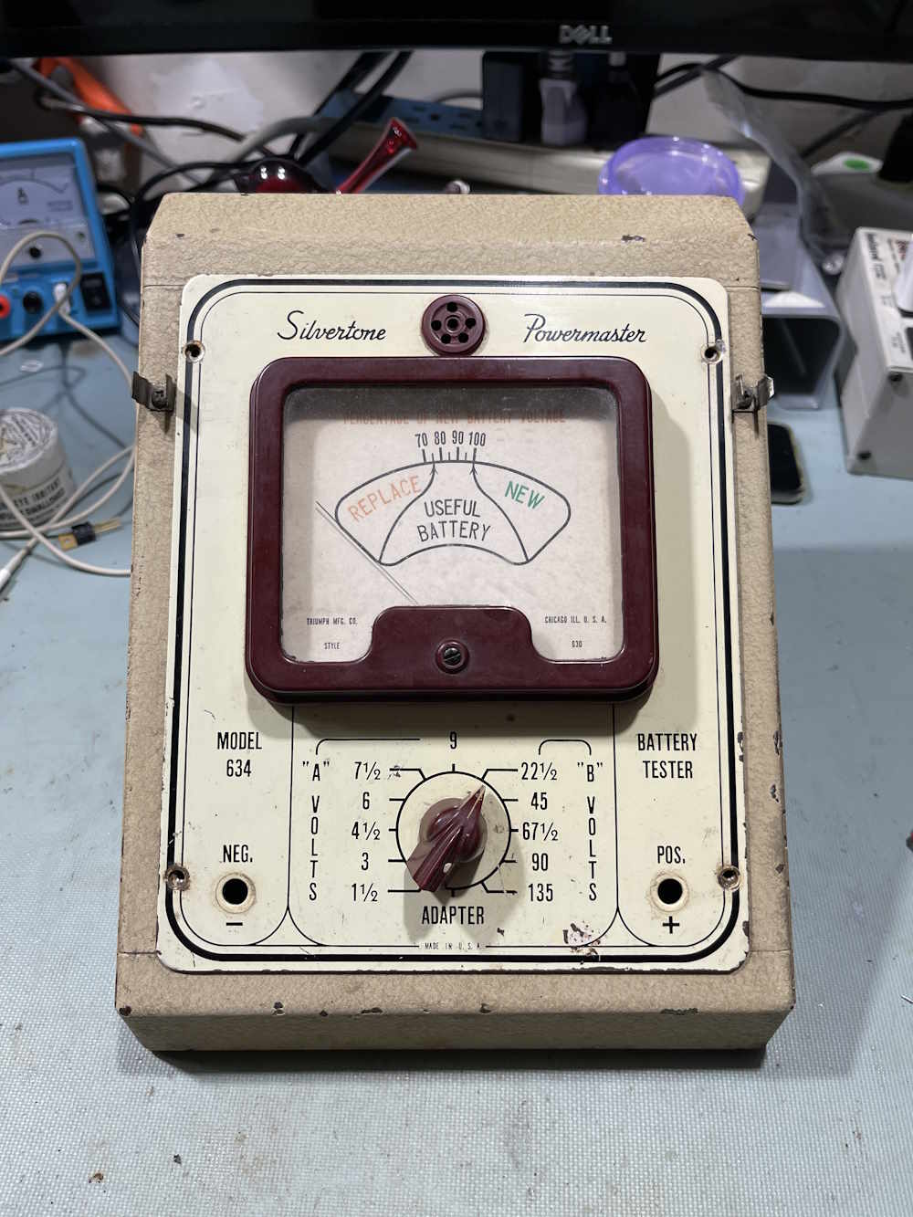
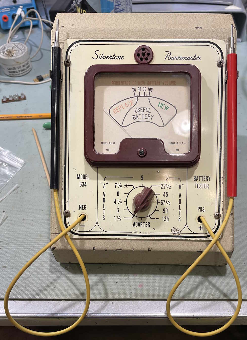
This is an interesting piece of radio history. Originally seen at the Findlay Hamfest in 2024, it showed up again in 2025, at which point I made the vendor an offer and took it home. Silvertone was the house imprint of Sears & Roebuck, once the “everything by mail” store in the USA. Sears expanded into physical stores, and devices like this unit would be sat on a counter at the radio department so you could test your batteries. Sears, of course, would be happy to sell you new “Powermaster” brand (another house imprint) batteries if yours were depleted.
The case itself is in ok condition, but it appears to have had some water ingress at some point. You can’t really see it in the image, but there’s some rust near the front of the slope. Note the two fuse clips near the top, those would have held the probes.
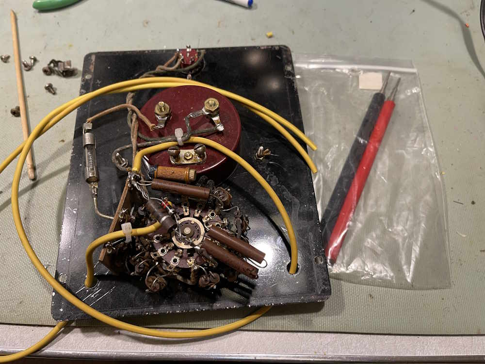
This is nothing more than a simple load tester, and is full of resistors to divide the voltage down for the meter and provide some load testing for the battery you’ve connected to it. It’s essentially a specialized voltmeter.
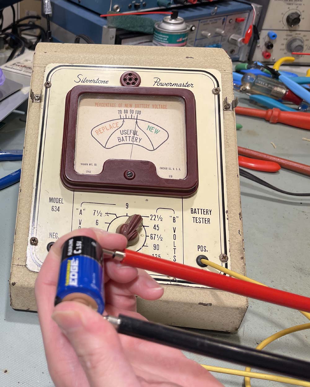
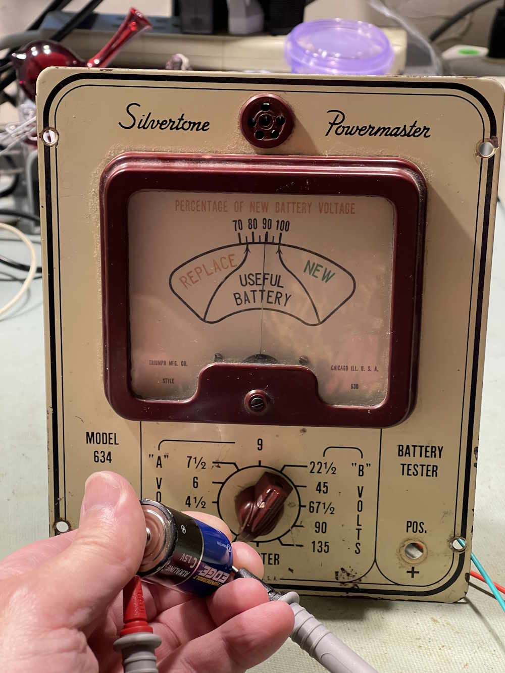
Before we go any further, does it work?
Sure does, this new battery reads decent on the unit. Probably will work a little better once probes are re-attached.
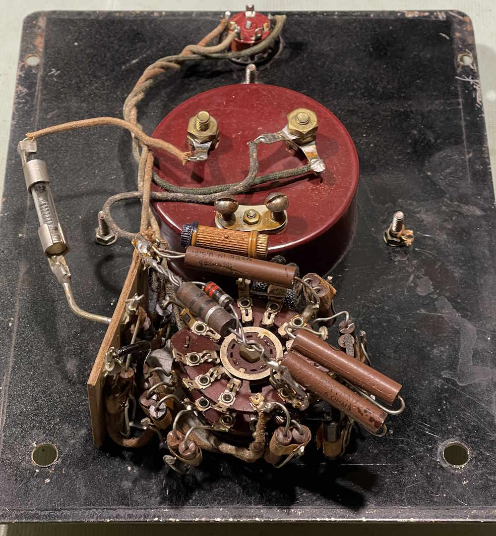
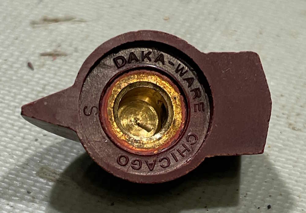
Of interest here is this knob. It appears to have been made in Chicago, and may have been sourced just for this device by Sears. After some research on this, the company, Davies Molding, appears to still be in business!
I have some cable and probes for the unit. Both of those were probably purchased at Mendelson’s Surplus many years ago, for far less than you’d get them today…I do miss that place.
It took a hot minute to figure out where the leads went, but after some investigation I determined that the negative goes to a big mass of resistors, and the positive goes to a terminal that has a second piece of phenolic on the switch. That one became obvious when I examined it with a magnifying glass and noticed it seemed to be a bit shinier than the rest, indicating it had been disturbed at some point in the recent past. Makes me wonder, did this thing have probes on it until recently and someone wanted those vintage pig pokers? Don’t know…
There’s still a bit left to do, I have some grommets on order for the holes and still need to solder the probes on, but this is what it will look like - eventually…
Stay tuned, this thing is going to work again soon!


 home.")