The Coolspring Power Museum is a large display ground consisting of member-maintained static displays consisting of everything from small oilfield engines to a giant across-the-state natural gas compressor engine, with everything in-between. Much of it’s up and running for the show, with other stuff in various states of rebuild or runs during a demonstration time. It’s a fascinating place, and they have engines and displays that you’re literally not going to see anywhere else - at least not in this condition!
All of the images here are of those static displays. There are other items that pull in for display during the show, but that’s primarily through the week. Saturday is the last day of the show, so most of that was gone by the time we arrived. Still…there’s so much to look at, and we’ll probably head back for the fall show this year as well. This one is well worth the time to visit if you have interest in old engines.
As with the MVSTA show, I don’t have much to say about these pictures - so here they are, in all of their greasy glory.
While this, and other engine shows I attend aren’t necessarily electrical in nature, they are certainly prime examples of old technology. I’ve always found the mechanics of such devices to be fascinating, and worth my attention.
The MVSTA show is one that happens on the Western edge of Columbus every year, and I try to make it out there at least every few years. This year’s show was bright and sunny with no threat of rain anywhere. Prime viewing time for all of the mechanical eye candy that showed up.
I don’t have much to say about these pictures, so no annotations.
This year’s show was maybe 2/3 the size of normal - I suspect the dangerous looking skies kept some people away, but fortunately the rain held off for the show. It was, however, sticky enough that you could probably have put a straw in the air and drank some.
There were still some interesting things to be found at this year’s show, and some good deals to be had. This is what I saw this year:
A Cushman broadcast band analyzer and a counter among the parts.
A board from an early Atari arcade cabinet.
A “Bedframe” antenna. Well built.
One of those early programmable scanners at the bottom of a pile. Used punchcards.
I believe this is the club's table.
An HP 3300 Distortion Analyzer and some sort of teaching breadboard.
What you expect to see at these shows.
A silent key's artifacts.
You could bean someone with that switch.
Just stuff.
More of what you expect at these shows.
An Edmont sound level meter with Coshocton, OH markings.
Some equipment that went home with me, all lonesome.
The decade box I brought home, should have grabbed the vibrator tester too.
I brought home some things that I didn’t need, but isn’t that the point of this kind of show?
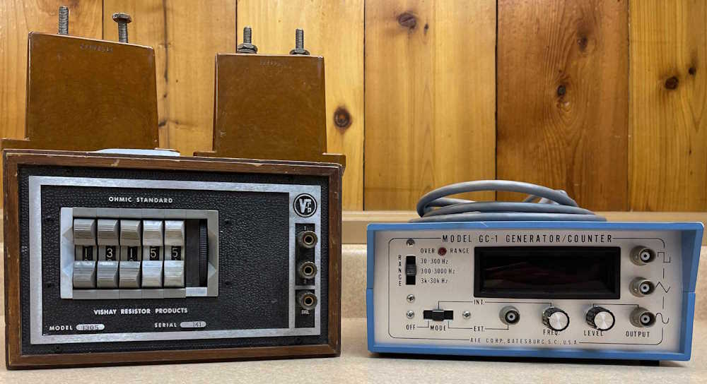
A Vishay decade box and a frequency counter / generator. They both seem to work well enough for the age. There’s also some high-voltage mica capacitors sitting on top of the decade box. Those were a buck, and I said why not?
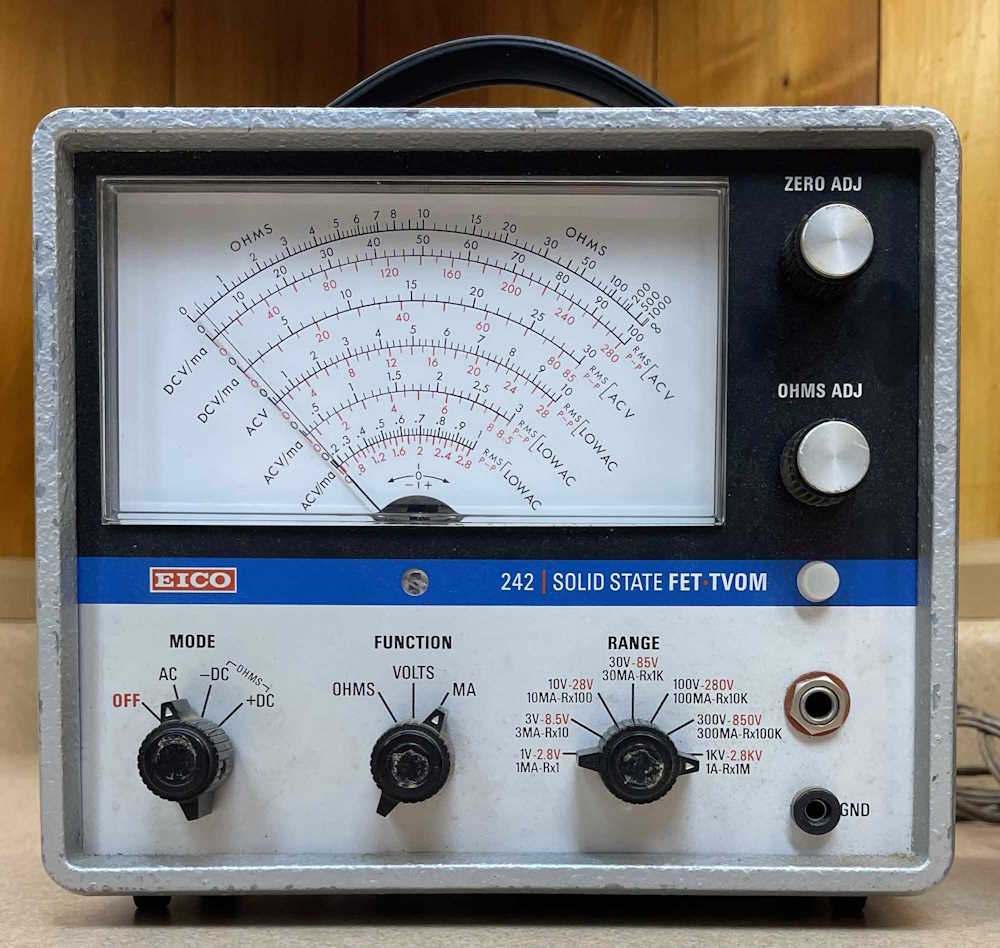
I can’t go to a show without bringing home at least one meter. Unfortunately, this one seems to have some issues, it will zero but not read. I need to open it up and make sure that any batteries left in it aren’t corrodeedoodled all over the place. It had a lot of bad resistors in the divider chain.
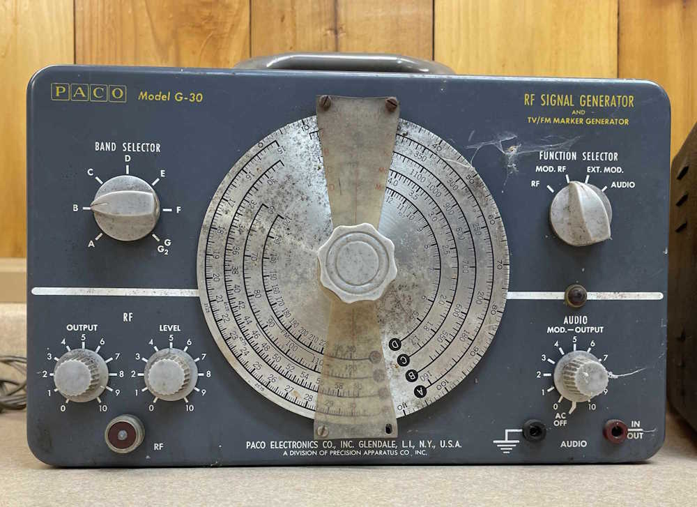
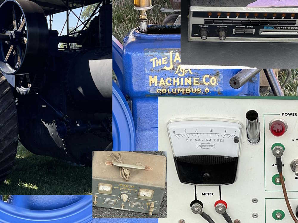
This PACO generator is the same as one I have in better condition. This one is a $5 parts unit.
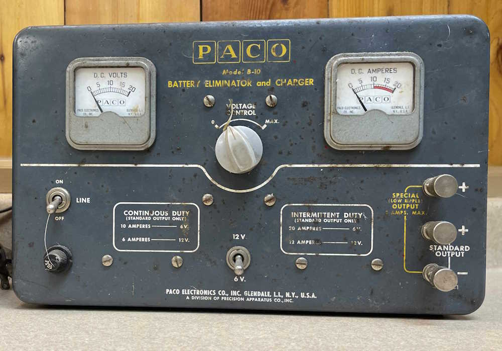
This is a PACO power supply that came from the same vendor as the generator, also $5. It’s an interesting piece, being an early bench supply for audio work, but in reality it’s a glorified battery charger. Stay tuned for a teardown on this guy. It eventually got passed on to someone for scrap. That’s what it’s worth!
No idea what this is, my fellow show-goer suggested it was some sort of early electronic switch for process industry. He’s probably right, but I got it simply for the cheapness of a 250VAC transformer that could be reused. I tore it down for parts.
That’s it for this year. I’ll be posting show pictures, and some other, recent engine shows as soon as I can get the images cleaned up.
One of my fellow show-goers was talking about taking some of the audio gear he collected to Dayton in 2025, and we’ll set up a table on the flea market. This sounds like a cool idea to me, I’ve attended shows but never had a sales table.
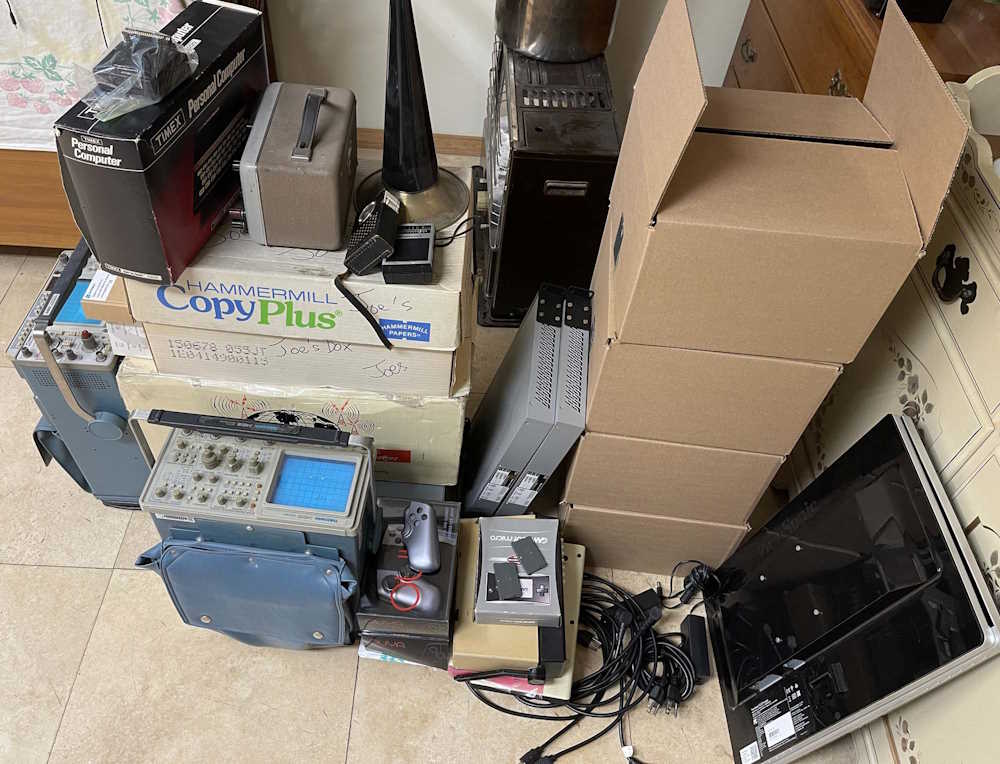
In the spirit of things, I took a look at what I’ve collected over the years that’s never going to go anywhere, and there’s a bunch. It’s time to start cleaning out, and I have a bunch of things that could go. Where does it all come from?
See you there, and maybe you can take something home! It’s cheap cheap cheap!
(If you see something you like, drop me a line on LinkedIn and we’ll see about a deal!)
Pictures from the Columbus Hamfest, Cool Spring Power Museum, and Miami Valley Steam Thresher Association shows are all in the works. There’s simply a lot of them and I have been a lazy little pig. Check back in the next few weeks and I promise that you’ll have some cool stuff to browse!
They’ve all been posted! Sorry it took so long on some of those…
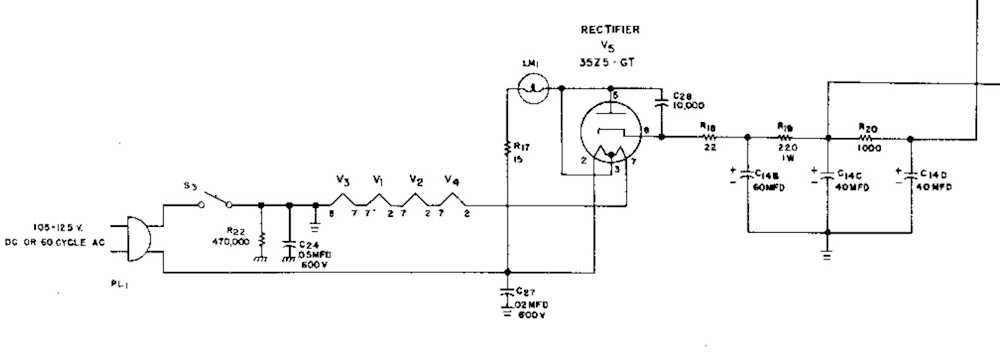
You’ll notice there’s a #47 lamp (Part# LM1) in the circuit for a lot of transformerless sets like the S-38C. It’s fed by a special tap on the rectifier tube:
It’s just a light bulb, right?
Yes and no. If you look at where it’s at in the circuit, it’s actually helping feed input current to the plate of the rectifier. This has the effect of both providing said current for the tube, and limiting the current available to the tube - you can draw about 60mA in this configuration.
So, do you need this bulb?
Again, yes and no. There are configurations where the tube is fed directly from the AC line, and this is a perfectly acceptable method. However, in our case of having the bulb, you have a bit of voltage drop to the plate which results in a lower output voltage, so you’d need to take this into account if removing the bulb - i.e. you need a resistor for some voltage drop. There’s also the fact that it is providing the AC current input - if you remove it, all of your current is now being sourced by the connection from the heater, and you’re stressing the tube. The radio won’t quit - but it just told you “Hey, I need service.”
In this case, the bulb is a component of the circuit that does more than provides light - it’s ballast for the rectifier and is providing a path for input current. It’s as necessary as the rectifier itself. You can’t replace this with anything other than a incandescent bulb without modification, so don’t grab an LED replacement for this one.
Fortunately, places like Antique Electronic Supply sell packs of 10 for under a fiver, so you can pick up a bunch and drop them in your parts bin. You probably want to do that anyway to get one that isn’t more tungsten boil-off than light bulb.
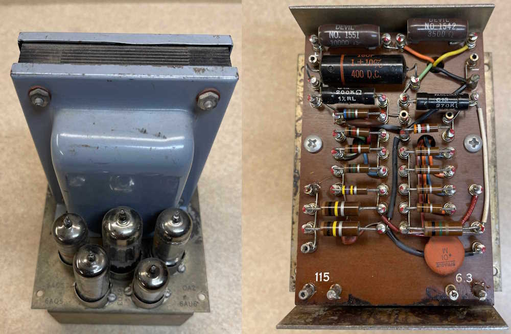
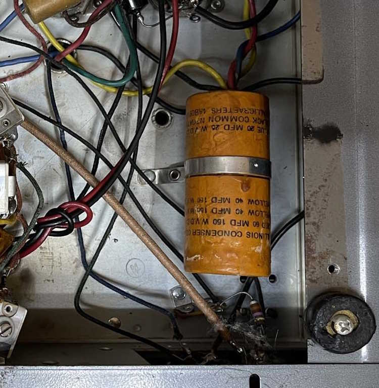
One of the things I picked up at Dayton this year was a really nice example of an S-38C multi-band radio. Completely untouched inside, it of course has bad filters. That’s par for the course for one of these. (It probably also has some silver mica disease, but that’s another day’s problem!)
Replacing them is easy enough, but it all depends on how you want to do it. Some prefer to keep it original, opening up the can on the multi-section device and putting new components inside. Others just wrap capacitors wherever there’s a place to put them. I’m thinking of going a different direction with this one.
Most of Hallicrafters low-end transformerless sets used similar multi-section capacitors and dropping resistors.
(Schematic from the Riders Manual.)
Some, like this one, used a 220Ω and 1kΩ resistor, others (like the S-95) used a 470Ω instead of the 1K.
So…why not create some sort of universal PCB that can drop in and replace all of the filter capacitors, sans the cathode bypass capacitor used in the audio stage of some of the units?
I had thought of using axial devices, but those can get expensive. What’s not expensive, and are compact and readily available? Surface mount parts. A small board could be created with three capacitors and space for the two dropping resistors, pre-assembled (or partially, depending on what you’re trying to fix,) and either double-side taped in or bolted down. The board wouldn’t need to have any through holes, wires could simply lay on pads and be soldered down. 5W resistors and 160V capacitors exceed original specifications, and would be easy to install on the board.
There’s certainly plenty of room in the device once the original can has been removed.
Wow, those feet are in bad shape…need to find some replacements!
I know that idea will offend some purists, but that’s not my concern here. I want to get the device back up and running with good quality parts that fit in the space required, without drilling a lot of holes or simply shooting parts all over the place.
I just need to brush up on my PCB skills, and lay out the board for sizing. Stay tuned!
A recruiter once told me that a company (that I had asked about) was generally known in the local industry for wanting to pay substantially under market - trying to be as cagey about it as they could. His comments about the place were substantially more colorful, but that was the gist of the statements, along with a “probably not going to be worth your time.”
The person telling me this had no connection to the company, so I put the info in my files, and thought that maybe they just had a bad experience with the place.
No, they were correct - I had a few offers to interview with this place over the years, and the pay for skills desired was very poor - probably about 1/2 to 2/3 of what others were paying. I turned down the few contacts I had with a “Thank you, but there’s nothing about your offer that makes me want to pick up and move across the state.
The last contact I had with this company, the person contacting me became somewhat (not really) angry that I refused to even consider the position. To be fair, I did have an online profile that stated a range of pay I was interested in, but this also was posted with the caveat of being for local positions only. Any movement would require reassessment of those rates. When I pointed this out, the person passive-aggressive told me “Oh, ok.” That was the last time I heard from them. I’ve since taken a look at reviews on job sites, and those suggest that things have not changed - or even increased a whole lot, if at all. There’s a lot of talk on these reviews about the complete lack of awareness and organization within the company.
I appreciate that information to this day. When I’m told there’s something not right about what I’m looking at, I make a point to at least investigate the complaint on my own. Even if the complaint seems to be unfounded, I still keep that in my back pocket.