When I was setting up redirects and closing pygg.xyz for the last time, I toyed with a bunch of ideas about how to properly tell the viewer that they had either reached their destination, or that the link they had was no longer valid. If someone had a link that wasn’t valid, I could simply let it go to the host’s 404 page - that’s not useful to the viewer, however.
The first option I tried was creating a simple 404 page with some information and links. That’s fine, but it’s just not the best looking thing in the world. I quickly abandoned that for a page at the end of the blog, “posted” long before any of the real posts were made. This worked, but…
Anyone that has a website of any sort knows that you’re going to get slammed by bad actors looking for entry points. In this case, those bad actors assume that since it’s a “blog,” you’re running WordPress. According to the site logs, I was getting slammed by requests for things in associated directories. There were quite a few other things as well. SQL, Oracle, SAP…all of those were common things being probed. There were even a lot of things I didn’t know what they were until I looked them up.
I set up the page at the end of the blog and checked back the next day. Exactly what you’d think happened, did. Hundreds of “views” in 24 hours, and I can guarantee you that none of those were actual people looking at that page. The view counter slowly went up with each refresh, indicating that the attacks were continuous.
This isn’t necessarily a problem, but it is in a way. If I were to let that page sit there, the site statistics would eventually show that page as being the most popular one on the blog - it would literally dwarf all other posts because it was getting hundreds of “views” a day. I didn’t want that, I want to give you things you’re interested in seeing. An error page isn’t interesting when you’re browsing the popular posts page.
I settled on a compromise. I took a static snapshot of the 404 page from “View Source,” cleaned it up to remove anything that’s not going to update, and made it the “Not Found” page. It looks almost like a blog page and has all of the sidebar widgets for navigation. This gives the viewer plenty of explanation as to why they are there, and what is available to them if they want to continue. This seems like the best choice - I’m not polluting the site with fake views, and a viewer who arrives there by accident has plenty of ways to find other content while landing on a familiar looking page.
Of course, as I read that page, it will change. Some of the things I write just don’t make any sense, and as I run across other situations those need to be addressed. In all, I think it’s a good place to land if someone does happen to find a broken link.
Maybe I’ll sit down sometime and analyze the WordPress script kiddies’ requests and create a special page for them that sends them to some weird government org. Probably not, they can sit on the 404 page just like everyone else.
I’ve been messing with various ideas for where pygg.xyz should go after it’s hosting plan expired. I finally settled on just having it redirect to the top level of Projects, with any errors going to the 404 page at the very end of this blog. This was done with redirects set in the domain registrar’s control panel.
The 404 page will get it’s own post. Stay tuned
DNS takes a while to propagate through the system, so I waited a while. Flushed the DNS resolver cache. Firefox and other browsers said no problem, here’s your site!
Chrome? Doesn’t work.
Did you know chrome has it’s own resolver cache, and even clearing that seems to have issues? I didn’t either.
You can’t get to that resolver cache unless you know the magic words. Put chrome://net-internals/#dns into the URL bar of Chrome and you’ll get to a simple text page where you can look up a named site and see it’s address, and/or clear the cache. Chromium browsers should follow this convention, but YMMV.
I cleared this cache on one machine, and my site started resolving. Another machine, and no luck. There seems to be differences between Chrome versions. That issue may cause some problems for people who have some very old links to this blog, but most of those should be gone by this point.
The moral of the story? There are more things to clear than you think there are, and even that may not work.
There was also some general crap going on with the redirects on the host. I cleaned those up and standardized them with my other domains, you shouldn’t have any issues getting here from there - but Chrome is still Chrome, and Chrome does what it wants.
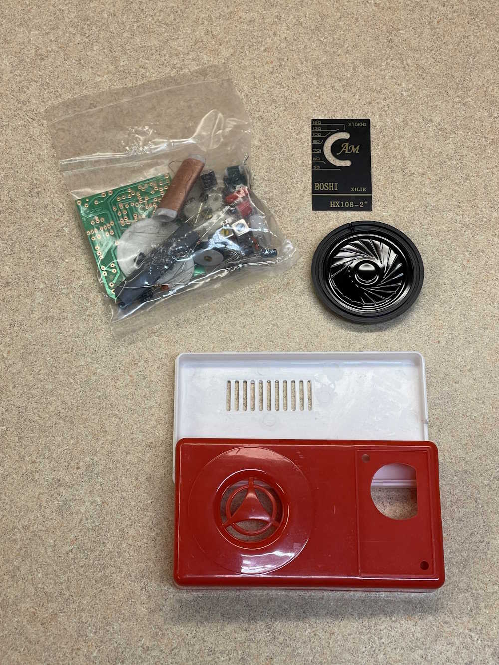
I picked this radio kit up from a popular import site. I’ve seen a couple of them built on random videos, and the price was right (under $10 shipped…) They work, but yeah, it’s cheap.
The kit consists of a case, board, parts, and “instructions.” No alignment notes or anything, so I hope this thing is 455Khz…
The instructions are literally just a schematic and parts placement diagram of sorts. It assumes you know how to align the radio, I guess!
If I get around to putting it together, it will be a bit of a challenge. Who knows when I’ll get to this.
This is probably the second oldest piece of equipment that I have in my collection, but this one is known working.
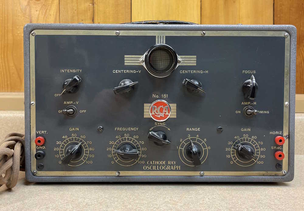
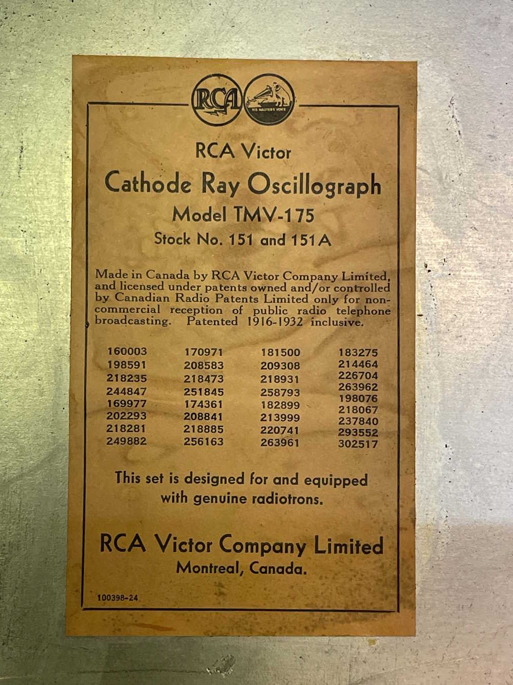
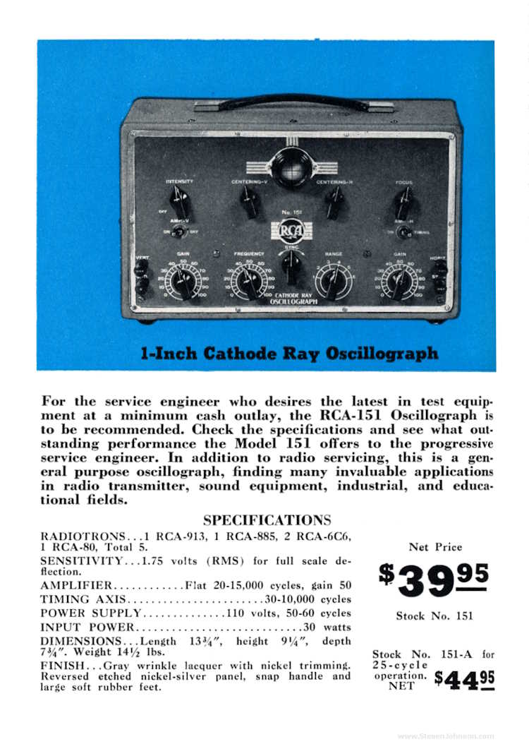
The RCA 151 Oscilloscope (or, oscillograph as it was known at the time) was one of RCA’s early test equipment products, and was supposedly one of the first scopes that was considered “affordable” enough for a small radio shop or well-off hobbyist to purchase. It’s not calibrated in any way, shape, or form, and doesn’t have the ability to lock on a trace - it’s just a purely visual indicator to see waveforms as they travel through a device. It has a top end of about 15Khz, and utilized a 1” RCA 913 tube for it’s display.
Of note here is the overall good condition of the device, both inside and out. I don’t think it was used much. Also of note is the input jacks - I believe these were biding posts at one time, but someone replaced them with banana jacks. Note the burn mark on the right where a hot lead hit the chassis instead of the jack!
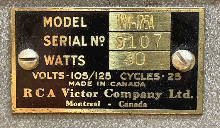
The device (and others like it) were made in Canada. This one is unusual in that it was meant for the Niagara Falls power standard of 25Hz - a system that was available until 2006, when equipment failure wrote out it’s final chapter.
It works fine on 50 or 60hz, the 25hz functionality being provided by some extra filter capacitance. As far as I can tell, nothing else changed.
If you’d like to read about that power system, the IEEE published a whitepaper on it in 2008. You can retrieve it from their website by clicking this link.
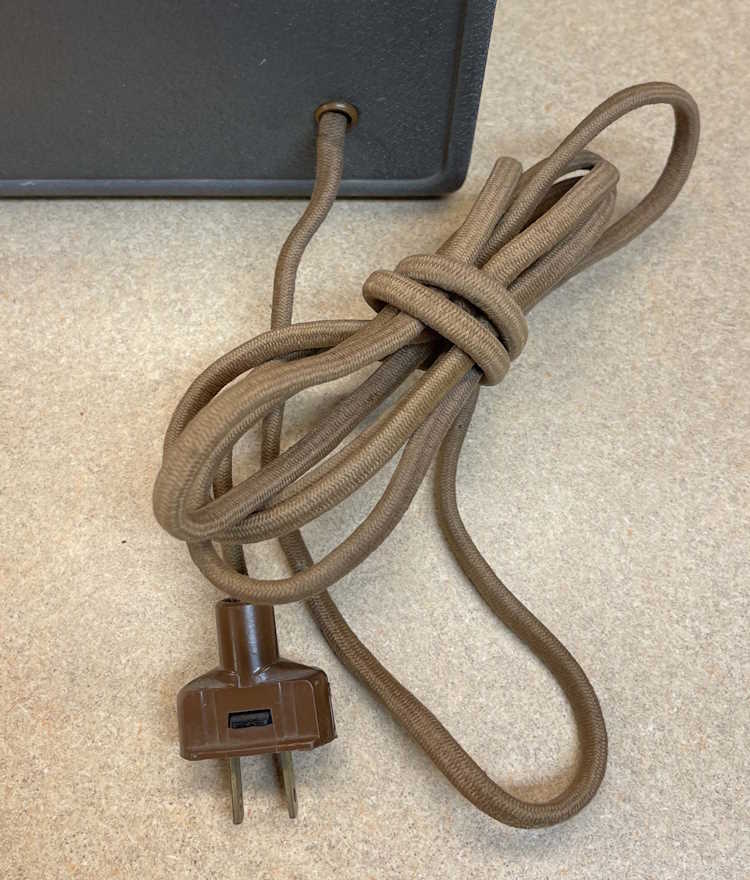
The cord and grommet appear to be original, from pictures I’ve seen. The technician plug, however, is probably fairly modern - no earlier than the 60s.
So, let’s get some stuff out and try it! My trusty CSC generator has outlived pretty much anything else I’ve had, so we’ll set it up.
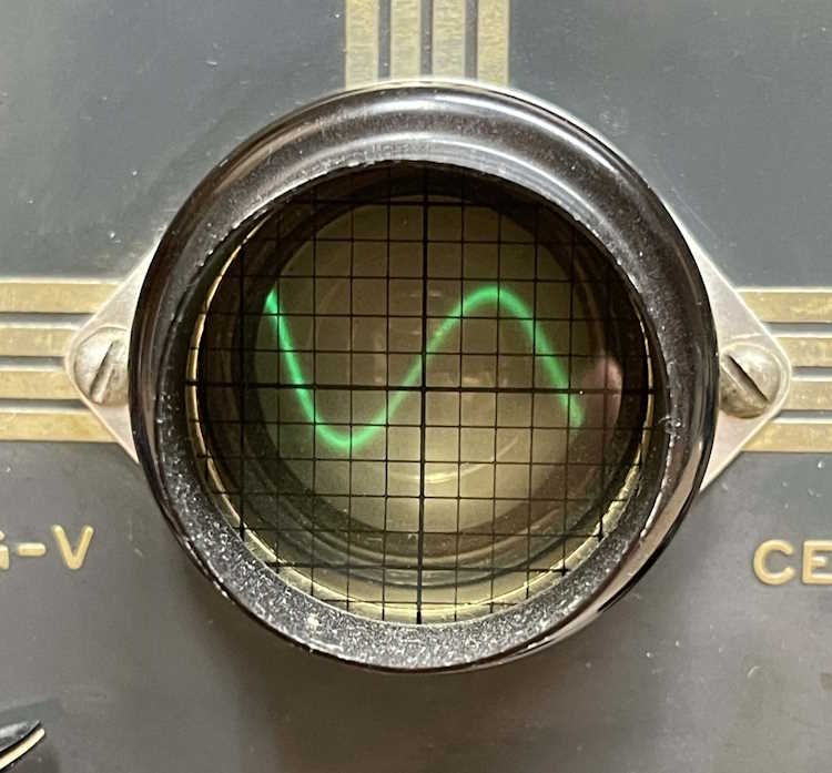
The display tube itself isn’t very bright. It’s just enough to see in a lit room, but works well enough. I don’t think this is age, I just don’t believe these were very bright to begin with.
It doesn’t lock because there’s no sync of any sort, so you have to mess with things to make it stable - and then it generally starts rolling again. As said, this was simply to show you the waveform.
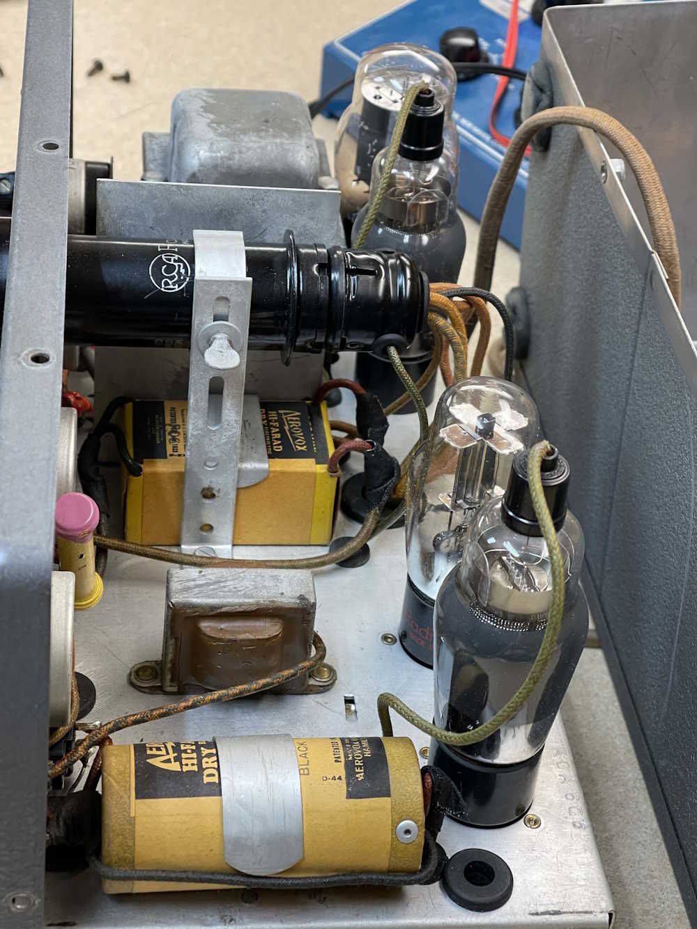
What’s inside? It’s a relatively simple circuit consisting of a Type 80 rectifier, two 6C6 for amplifiers, and an 885 Thyratron for the sweep - essentially this is like SCR sweep in a late Sony CRT Television.
Everything is in really superb shape here - no rust and very little oxidation on anything. This thing must have been a prized piece that sat on a bench.
Note the capacitors - that big box capacitor in the middle has been spliced in and the joints coated with old-school cloth electrical tape. I would assume that RCA would have used their own brand parts at this time, and not Aerovox capacitors, but I’m not sure - but this most certainly was repaired at some point. The old dry Aerovox ‘lytics are still good, to this day, so whatever technician made that choice - I salute you, sir.
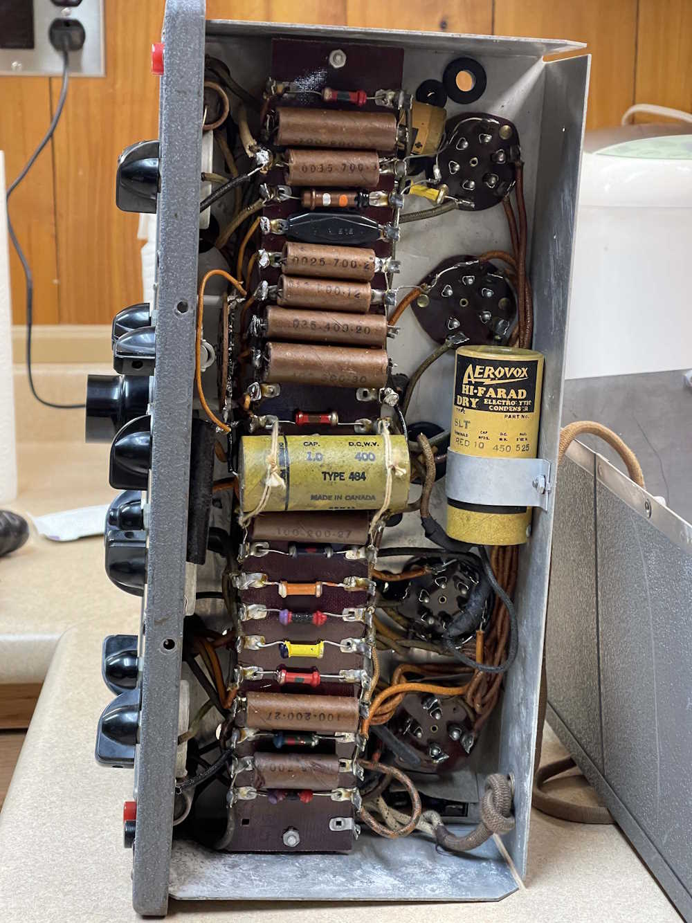
The bottom shows the parts of the era. Dogbone resistors and lots of capacitors here with minimal marking. It’s all on a terminal board, so completely rebuilding this would be easy, if it was necessary. I don’t ever plan on using this thing on a daily basis- so it’s not.
There’s more of those Aerovox capacitors. Maybe that was original? Did RCA just take an off-the-shelf unit and splice in an extra capacitor for the 25Hz model?
The entire thing has that “smell” of old electronics. You know what I mean.
Last - the paper label inside is still intact.
Time to put it back together and back on it’s display shelf.
There’s plenty of information out there on this device, including ads and manuals. A good source for that information is located at The Oscilloscope Museum, which displays it’s own example of the device. An advertisement for the device (also from the aformentioned site, check it out!)
_
My device cost $44.95 - that’s $1015 today!
Maybe not so cheap for a well-off hobbyist, but certainly invaluable to the radio shop…
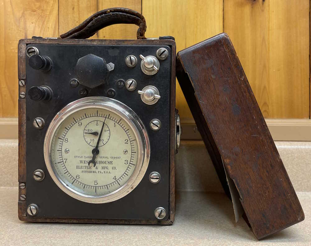
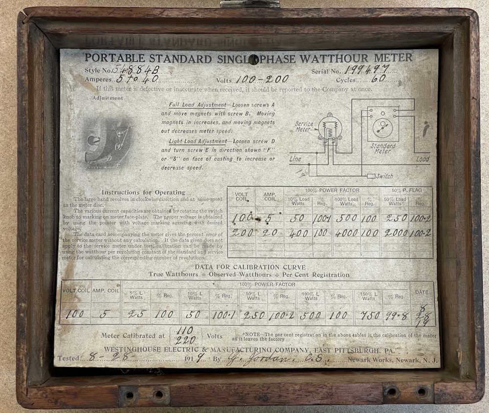
This is probably one of the oldest pieces of equipment in my collection that could sensibly be considered “electronics.” This is a watt-hour meter made by the Westinghouse Company of Pittsburgh, PA, and was designed to be used as a calibration standard for other measurement systems.
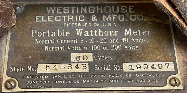
While the case itself has seen some better days, it’s still relatively intact for a device from 1919. A few cracks, and the hinges were missing when I got it. It has a lovely brass nameplate on the top:
I love the patent dates here. That’s 1895.
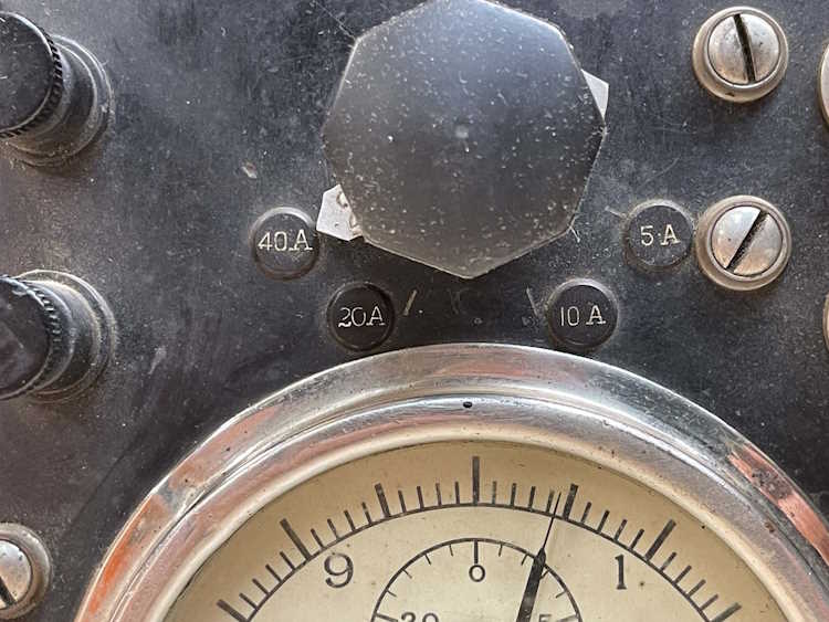
The actual range is selected by a big knob in the middle. There’s no clunk of detents, but the knob has two pointers. They’re lableled “1” and “2” - the knob turns all the way around so I assume that it’s a brush inside the device riding on something that connects a shunt for the current portion of the meter. Not sure at this point, however. I have to assume that the numbers are for the incoming voltage range - but again, not really sure.
The really cool thing about this device is the instructions and original calibration card are still in the lid:
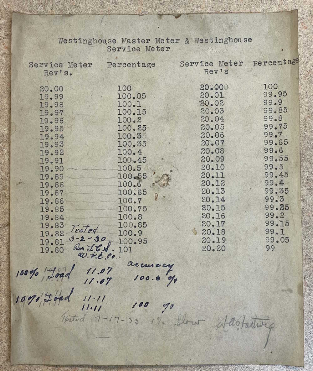
And even more cool? There’s a calibration sheet with notes from 1930 and 1933 on it:
But the million dollar question here is does the thing still work? No idea right now. I need to open it up and make sure there’s nothing inside that’s broken first, and do a little study on the instruction card. For now, it’s just a neat display piece, but could potentially be put into service in a pinch - if the innards are still good!
This is a benchtop test box I picked up at the Breezeshooter’s Hamfest this past June. It’s simply a switched, fused outlet with some indicator lamps and a current meter. It proclaims itself to be a Waage Electric Model 066, “All Purpose Tester.” It’s in eh shape, and probably sat on someone’s bench for decades.
The cord is in good shape, which is surprising for the age, but both the neon pilot lamp and the little 7W peanut bulb for the circuit test are dead. It was probably “on” for most of it’s life. The neon bulb in the pilot doesn’t even do the flickering thing at this point.
Everything seems to be mechanically working, the switch snaps with a nice thunk, the meter pointer moves but needs to be adjusted, and all of the sockets are intact. Of note here is the Edison Fuse - no 3AG glass fuses here!
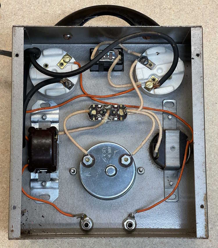
The inside is pretty clean, overall. I can immediately see the cord appears to have been replaced because of the way it’s put on the screw terminals - it’s unlikely the factory would have shipped it all birdcaged out like that. So that’s probably a new(er) cord.
Of real not here is the small gauge wire used for the device. The orange wire appears to be about 22GA solid - that’s not going to handle the 15A this thing is supposedly rated for. It makes me wonder if this thing was completely redone at some point in time, as there’s a mix of thermoplastic and cloth-coated wire in this. It’s of an age where everything would have been cloth coated.
In all, it’s kind of a neat piece, and was probably meant for testing products of the kind that Waage made - heating devices such as irons and coffee pots. For the $1 I paid for it, it’s literally a nothing lost proposition.
If I wanted to use it, the non-polarized outlet would need to be replaced, as would the cord and small gauge wire. I’d probably try and save the original pilot lamp, and find an incandescent bulb for the test socket.
But who knows. It’s of limited use other than a “That’s cool” thing to have on your bench. I’ll probably clean it up and see what I can do with it, stay tuned!
If you don’t, geocities was an early “personal web space” host that allowed you to create a simple page. They ranged from fan sites to personal ramblings, with some information and everything else in-between. I collected a lot of useful things off those pages, including stuff like pre-made plugins for software, links to companies of interest, and images of otherwise unobtainable things.
These sites were more often than not characterized by garish backgrounds, flashy things, more fonts than you knew existed, sound and music blaring out of your speakers, and all of the Under Construction GIFs that your machine could possibly handle without melting your video card.
I used mine as a holder for links that I could hit with my BlackBerry, among other things.
But, in 2009, Yahoo! decided they wanted to discontinue the service - 10s of thousands of web pages, full of information from the old internet, would suddenly vanish - and it would have if not for the efforts of companies like geocities.ws, among others. There were many projects to collect as much of this data as possible. Personally, I think Yahoo! really did a big F*** YOU to the internet by not handing over the archives - or at least keeping it static. It’s not like their draconian TOS didn’t give them the right to do whatever they wanted with your data.
Regardless, I found my site in the .ws archives and claimed it by having them send email to the (at the time) existing yahoo address of the same name. It’s been a few things over the years, but right now it’s a quick-link to this place, with a few preview images.
While there’s nothing on that site you haven’t seen before if you’ve been browsing the wereboar pages, it’s still there just in case. Why not, it’s a small free space to host something. If you had a geocities webpage at some point, there’s a chance it in the geocities.ws archive. If you have some way of claiming it, like the yahoo address associated with it, you may as well do so. Time to relive the old internet, party like it’s 1999, and use at much comic sans as you can!
(no epilepsy inducing flashing images or synth-pop that blows your speakers out, I promise - and I won’t even open your CD tray.)
I wonder if I should put a hit counter on it?
If you’d like a copy of the entire archive as retrieved by ArchiveTeam as the place was shutting down, you can find it on that site by the bay…the one where the skull and crossbones fly. Search for “Geocities” and select the one that claims it’s patched - the other one has issues and won’t complete. The files are fairly well looked after, so you shouldn’t have any issues retrieving it. It’s almost 700GB, so make sure you have room for it, and the 1TB of uncompressed data.
I took a lot of pictures at the show this year. The individual exhibitors had mostly pulled out by the time I arrived, but the museum’s displays were all up and running in their greasy glory. I haven’t had time to fully process the images for display here, but they’re on the way.
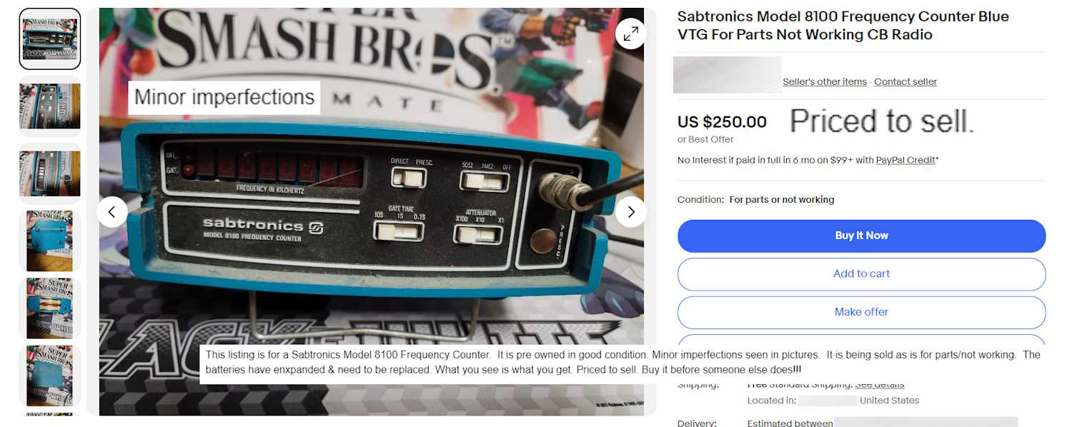
I picked one of these guys up at Dayton for $20, modified to work in the 2M band. Figured, hey! I’ll pick up some parts units.
For some reason, a non-working device with a (hopefully intact) broken display cover, swollen batteries (and quite possibly corroded inside,) no battery cover, no (oddball) power adapter, and covered with dirt for $250 doesn’t inspire me to add “Priced to sell” in the description. Especially when the device has been superseded many times over with modern equipment at lower prices.