Recently, I updated my Home Assistant system with a couple of new items that enable thread and matter support. The first is the official “Home Assistant Connect ZBT-2,” a device that much like it’s predecessor, allows either ZigBee or Thread/Matter connections - but not both. The second is one of Ikea’s new Matter devices, a “Timmerflotte” (wood raft) temperature/humidity sensor with a name that was obviously pulled from the same void that most of Ikea’s names are pulled from.
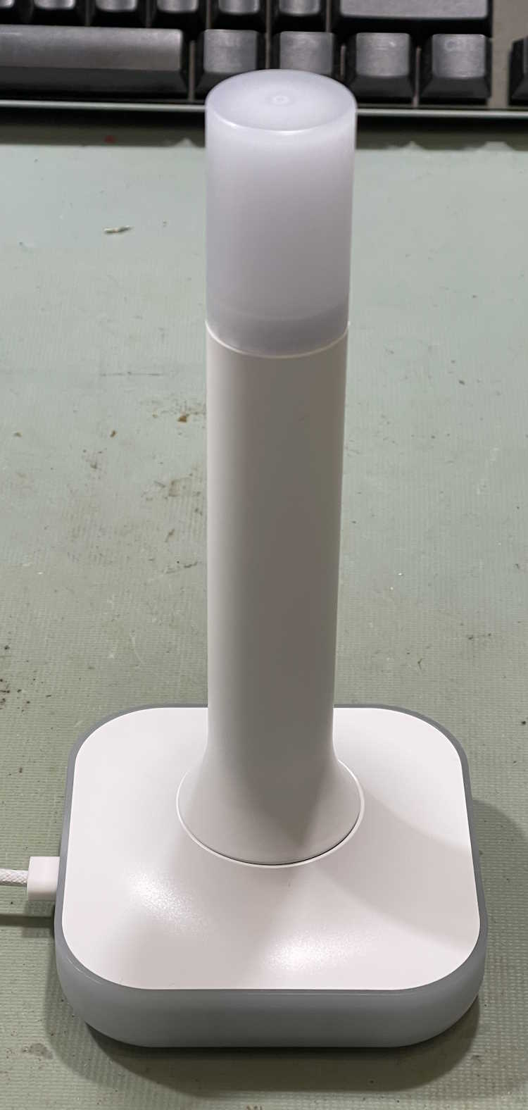
Here’s the ZBT-2:
This is basically the z-wave device’s little brother. It supports a ZigBee connection, OR can act like an Open Thread Border Router for Thread devices. It’s a beefy device, heavy enough that it stays put, and comes with a decently long USB A to C cable for connection to your HA device. As it has a real antenna, the range of this device should be much better than the little PCB antenna on it’s predecessor, but YMMV here as I can’t test that due to all of my devices being in a relatively small area that the ZBT-1 has no problem reaching from the other end of the house.
You’ll notice this device has a translucent top. That’s because there are 4 RGB LEDs in the base that transmit light to the top via a lightpipe. You can’t use these LEDs from within Home Assistant, however, so I’m not sure why they are there. The unit lit up blue during the initial setup, and now it’s dark. Unless they’re going to add these as a controllable entity later in the process, I don’t know why they are there - it’s just added expense and devices that will never get used.
This device should just be plug and play, however, when I plugged it in my Home Assistant Green didn’t see it. A reboot didn’t cause the device to see it. I unplugged and plugged a few times before the Green finally decided it was connected. After connection, you have to choose what you want it to be, and I chose Thread. Home Assistant then begins to upload the firmware and configure the device, after several minutes it releases it and you’re ready to start adding things.
I did notice that, according to Home Assistant, this is a “bronze” level support device. Why is a device made by the official provider of Home Assistant - it’s own product - at a lesser support level than the top tier? I have no idea, but that seems to indicate to me that they rushed this out a bit earlier than needed. There shouldn’t be anything lower than platinum (top) tier support for your own product.
But, after messing with it for some time, it did work, and appears to Home Assistant as what it should be.
The device I wanted to add was one of Ikea’s new Matter sensors. This one, the Timmerflotte, is a standalone temperature/humidity sensor. It uses AAA batteries, which is a nice feature. It’s rather large, however, but does offer a hook hole on the back for you to hang it on the wall or wherever. The batteries are under the back which pops off with a little screwdriver slot. You can also access the reset button here, as well as the C°/F° switch. They come set to celcius, so I switched the device while I installed batteries. It immediately goes into pairing mode when you put batteries in, but will time out after a while. I set it aside and let it time out.
You’ll notice it’s big. Bigger than other temperature pucks. At least you would have if I’d given some scale…sorry about that! It also has a display on the front, a white LED display made up of point-source LEDs that activates when you push the top down. It shows temperature, then humidity, then turns off. That’s cool and all, but only if you have it out where you can access it. If you’re using these for measurements in, say, a cabinet or some other hard to access place, it’s kind of useless. But it’s there, and I guess someone thought it was a good idea.
So, how to connect it to Home Assistant?
The ZBT-2 process installed the needed Thread components, andI I installed the Matter component in HA’s devices and services. No issues there.
The weird stuff started after that. There’s no easy way to add a matter device to your system when it’s running over thread. With ZigBee, you put your host in search mode, and push the pair button on the device. Device and host have a conversation about capabilities, and you’re done. Nothing else needed. Matter - at least over Thread, I haven’t had a network device to try yet - requires a middleman. In this case, you have to take a picture of a QR code with your phone, or link via BlueTooth first before the host can find the device. Another layer of complexity between you and getting this device on your host. So, I used the camera (which was very flaky about finding the QR code, it kept wanting to identify the batteries) to capture the code. It started to pair. I had also held the reset button on the timmerflotte until it started flashing an LED, I’m not sure if you need to do that. The whole thing is somewhat arbitrary, but it didn’t seem to hurt.
And just sat there, and failed.
Why?
No indication of errors in Home Assistant, which is certainly a problem endemic to Home Assistant and it’s services. It’s very unhelpful when something fails, this particular service didn’t tell me anything about the failure except that it did. But, I finally figured it out - Matter requires IPv6 to work. Why does it need this for a local radio protocol? I have no clue, but it does. That’s how Matter is written. No IPv4 for you! Of course, I’ve had IPv6 turned off on the router since it was new, as it’s not necessary for a home network to have it and it’s caused me problems in the past. Turned it back on (thankfully I hadn’t deleted the IPv6 package) and enabled it in Home Assistant, and there it goes. It connects, adds, offers a firmware update, and everyone is happy. I’m able to put it in graphs and automations.
So why the IPv6 for a local radio protocol? It doesn’t need it - but Matter is capable of being used on multiple carrier protocols - Thread, WiFi, BlueTooth (I assume, anyway,) so while you don’t need it for the Thread connection, you can have many many devices on WiFi without running out of addresses. I guess if you’re planning on having 250+ units on one network node, that’s great. Otherwise, it’s just another network protocol you must have on simply because some dev thought it was cool.
So what would I do differently here? The Matter service in Home Assistant just assumes things, much like Home Assistant assumes that the time your router is giving it is correct. Assumptions lead to broken things, and this was no different - the Matter service should immediately check to see if IPv6 is there, and if not then stop and say so. Or at least check when it’s installed. That’s the biggest problem I’ve found with HA, that of assumptions. You can’t and shouldn’t do that. But they do, and it breaks.
But it’s fixed for me, and hopefully this will prevent some grief for you. Just remember, X10 forever!
A few days later…
The Timmerflotte worked fine for about 3 days, then started dropping off and then refused to connect. There are many many reports about these devices being unreliable, and the entire matter-over-thread ecosystem being a mess. There’s even a big github bug report about it where a dev angrily talks about how you need good RF penetration to make it work. See https://github.com/h … uecomment-2604219962 for that thread, and basically just search on timmerflotte disconnect from home assistant for a lot of noise on the subject. On that, I would think the ZBT-2 stick is a good RF network provider, but I guess not?
The short story is that matter can be unstable, especially if you have older devices. Some have good luck, others do not.
I did try to move the sensor closer to the antenna and re-power it, but it just doesn’t want to connect again, even though the device still functions as a press-to-see sensor. I do have some more on order, I may end up just taking them back until the ecosystem matures.
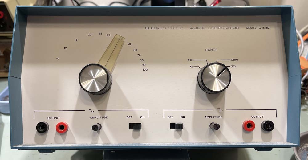
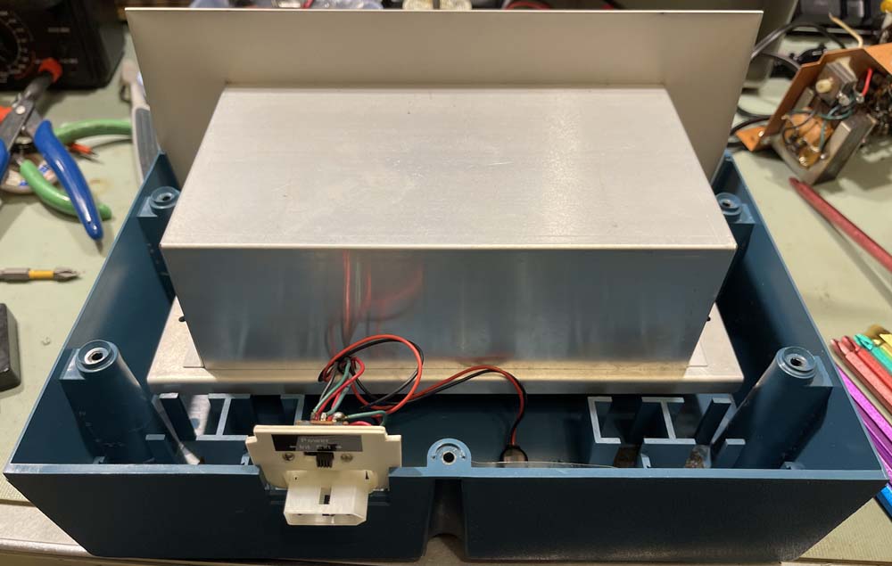
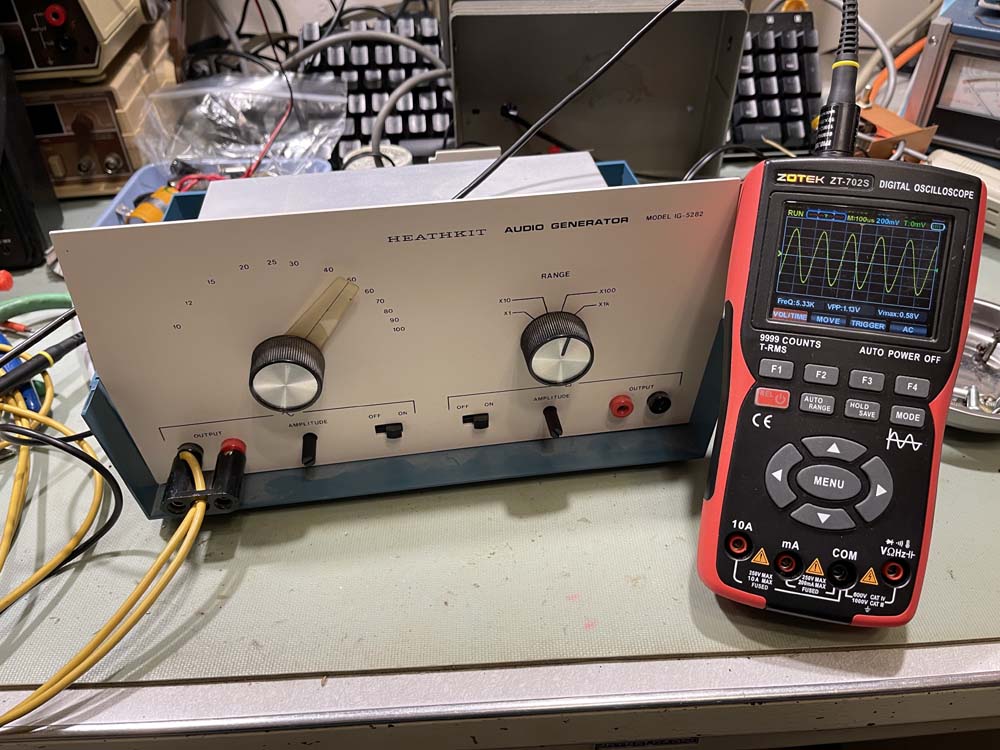
This is a Heathkit IG-5282, an audio signal generator that goes along with the IB-5281 bridge. There’s a post about the bridge here: https://wereboar.com … -odd-heathkit-stuff/ if you’d like to read it.
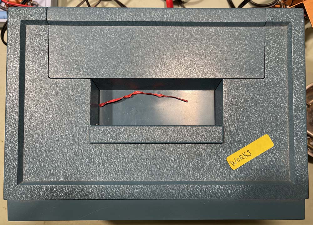
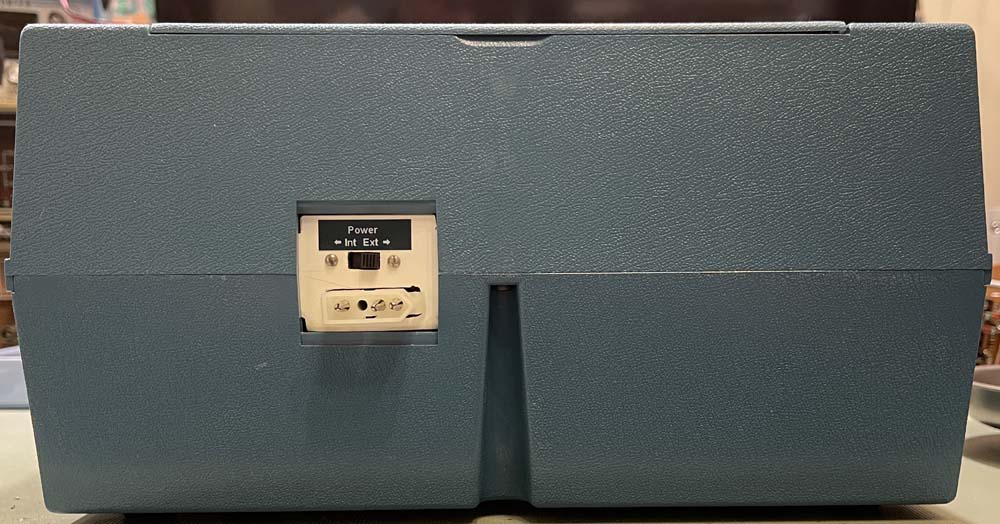
This device is in the same series, and comes in the same blue case, same dimension, same everything save this one has the correct molex connector for the power input.
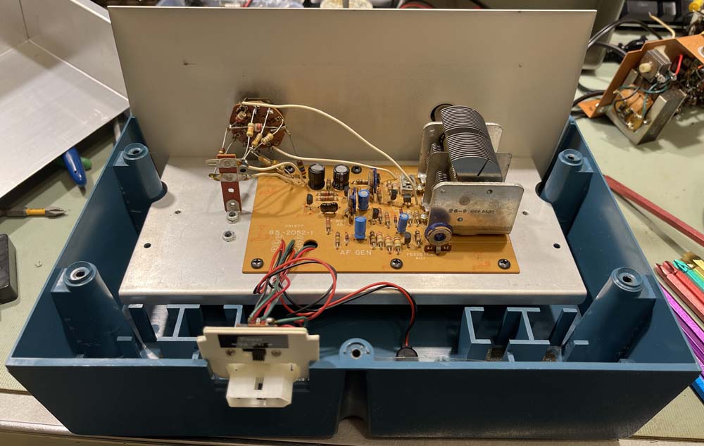
Inside, the entire chassis is shielded, but comes off with two screws.
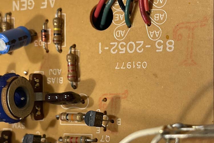
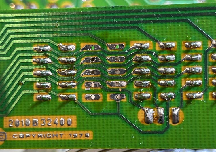
While I haven’t pulled a schematic, one expects this to be a generic weinbridge device. The circuit board, of course, exhibits the magical orange “T” indicating the raw board was made in Ohio.
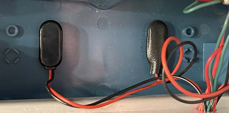
Does it work? Let’s put some batteries in and see. This requires 2 9V cells or a power supply, just like the bridge. One of the things I noticed here and didn’t notice on the other, is that there are places on the bottom of the case to hold the battery snaps down so they don’t fly all over the place. That’s pretty neat.
Let’s power things up.
You can see by the sinewave on the scope that it indeed does work. The dial indicator doesn’t match the output at all, so yeah. Whatever. It seems to go from about 7Hz to near 120kHz, with the top clipping a bit when driven hard.
To get square output, you turn on the sine then turn on the square on the front panel, as the square output is derived by shaping the sine. It’s accordingly lower in value and frequency:
It seems stable and works as prescribed, even if the output is a bit weak in the amplitude department. Ok, another piece of odd equipment for the bench, a non-line powered generator may have some uses.
One more piece in this set, and then we’re on to other things. Stay tubed!
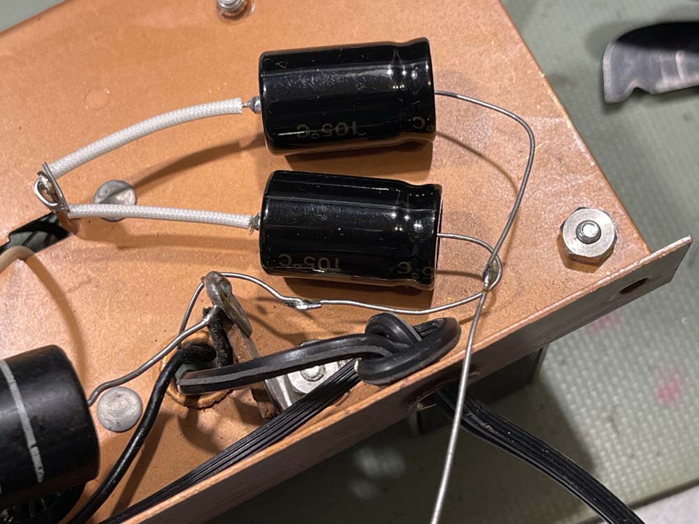
We had a snow day weekend, so I decided to continue replacing the capacitors in the Simpson 715. Today’s subject is the two parts at the top of this stack:
Since the leads on the new ones were much shorter than the old ones, I had to stretch them out a bit by j-hooking the leads and sizing them by pulling to their destination:
Then it was a matter of running some electric sketti on to the leads for protection.
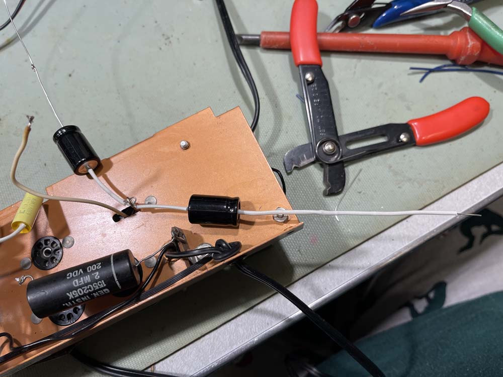
After that, it was just a matter of running them to their destinations. I didn’t solder them down yet because there’s going to be more work to do here in the rectifier section - the lead will need to come off so we can measure draw in order to size the new dropping resistor when the selenium rectifier is replaced.
That lead will need to come out. The other side of the filter pair has been wrapped around it’s post, but not soldered either since the 10k for the second B+ will need to be installed.
When it’s all said and done, the new ones take up a bit more floor space than the old one, but less space overall.
In the meantime, I decided to clean up the meter board by removing the old dry electrolytic and poor soldering. I also prepped the 30Ω resistor that will need to go back on the meter board. The solder came out easily when a little new was added, and all it needs is a bit of alcohol to clean up the flux.
A forum friend suggested that the diodes be checked for leakage before reinstallation, or just replaced. That’s an excellent idea.
The capacitor that came off this board is probably fine. ESR is a little high, but capacitance hasn’t doubled like some of the others.
During the filter install, I noticed something. See this terminal, and that wire wrapped around it?
That lead isn’t soldered. I believe myself to be the first one in here, so that’s been like that since the device was new. This wasn’t a kit device either, even though the construction quality would lead you to believe otherwise. You’ll notice the solder blob at the top is rather poor looking as well.
That wire is a 1kΩ resistor that runs under the chassis. To be fair, it doesn’t look good on the underside either.
That part came out, but was fine:
But was replaced anyway because why not.
The terminal soldered with a bit of flux.
I wonder if this is the problem the meter had, as this is right in the drive line for the meter. If it’s working when I repower, I’ll assume yes because none of the capacitors have been noticeably bad except one.
The Sabtronics 2010A Meter on the bench has a bad display, and I was able to find some NOS parts for it. Let’s put it in!
The dead segment in the unit was working for a while after I acquired it, even though the vendor said it wasn’t. Perhaps this was due to the device sitting in hot sun for a while and warping whatever was broken in the display back together. Regardless, it didn’t last long.
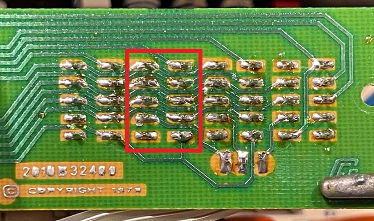
The unit comes apart with four coarse screws, and then the display board unmounts using two short screws. There’s enough cable attaching the mainboard and display board so it’s easy to pull back and identify what needs replaced, and where:
In order to remove the solder, I hit it with a bit of fresh solder and then used my good wick to take the solder off. It came off nicely and cleaned up with a bit of alcohol.
Then it was just a matter of verifying the new part and the old part were identical, which they were as they were both Fairchild FND-357 displays. I did have to clean up the legs on the new part by scraping them down, as there was 40 years of oxide on them. That was just a matter of a hobby knife blade run across each leg a couple times.
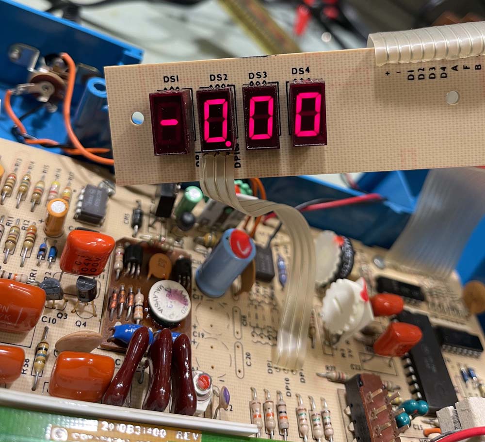
The display worked perfectly, as expected.
I also took the time to clip and cover the leads to the old battery box, which was broken beyond use. I may put another one in later, but there’s really no need.
That’s all for this one, it’s back on the bench and ready for use.
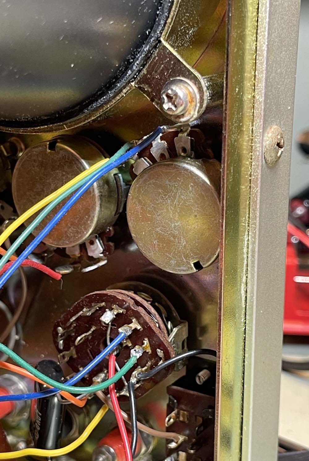
In the first part, we checked out a Leader LBO-310A oscilloscope. It seemed to have a very simple problem, one where the vertical centering wasn’t working. This is due to a bad potentiometer where the carbon ring on the internal wafer is just worn from age. The pot in question is the one closest to the edge in this picture:
I picked up a few parts, but it turns out this one is just a little different. Older Japanese equipment tended to use potentiometers that were just a bit smaller than the ones we used in the USA. 6mm shafts instead of the 0.250” (6.35mm) that we used, with a correspondingly larger mount. So…the ones I bought won’t fit. I could make them fit, but then the knob won’t fit the shaft.
So…
I have some on order that claim to have a 6mm shaft. They’re genuine Alpha pots, so they should. “Should.” If not, hopefully I can just remove the wafer from one of them and swap it out. Otherwise, it’s waiting for a show where I can dig through some junk bins.
I recently undertook a task to clean up and optimize images here on Projects, both for size and content. Some of the images were simply enormous, and some were showing stuff not relevant to the task at hand. You don’t need to have 5MB of image downloaded just to show you my bench with a single part on it. It can be much smaller. I also wanted to name things with a more universal convention.
That has been, more or less, completed. There’s a few images hanging out in hamfest folders that could be touched again, but for the most part they’re fine. And a couple I missed in QA…
Enter part 2.
Flatpress has a plugin that allows the pages to present a set of metadata that makes it more friendly towards searching. I’ve decided to (slowly) go through the pages here, add descriptions and keywords, and hopefully make the site easier to find what you’re looking for. This is probably going to take a while, but you shouldn’t see any interruptions on the front end of the site. I’m going to be working forwards from 2021, with 2026 already fully metadata’d.
Thank you for visiting Projects. I hope you’ve found something of interest here.
Progress:
2026: Done
2025: Done, and found some missing images.
2024: Done, and found some missing images.
2023: Done, and found some missing images.
2022: Done
2021: Done
This project is pretty much done. I’m going to set the search engines loose on the site in the coming weeks, hopefully more links to the site should show up and provide easier searching.
Here’s a device I picked up as part of a stack of stuff - A Heathkit IB-5281 RLC Bridge. This is a “more modern” equivalent of the old eye tube tester, and dates to the late 1970s. This is probably the last gasp of this type of device, as digital capacitance checkers started to become more readily available as the 80s moved on.
There was a whole set of devices in this range including:
AF Generator
RF Generator
RLC Bridge
Signal Tracer
Multimeter
They’re all in giant blue plastic boxes:
The device has a fairly short range of values it can test, and definitely seems to be geared towards the transistor era. One of the neat features is this device can also do matching by comparing the component in Zs with Zx, and dialing the main indicator away from 1.0 to give a determination on how close a match they are.
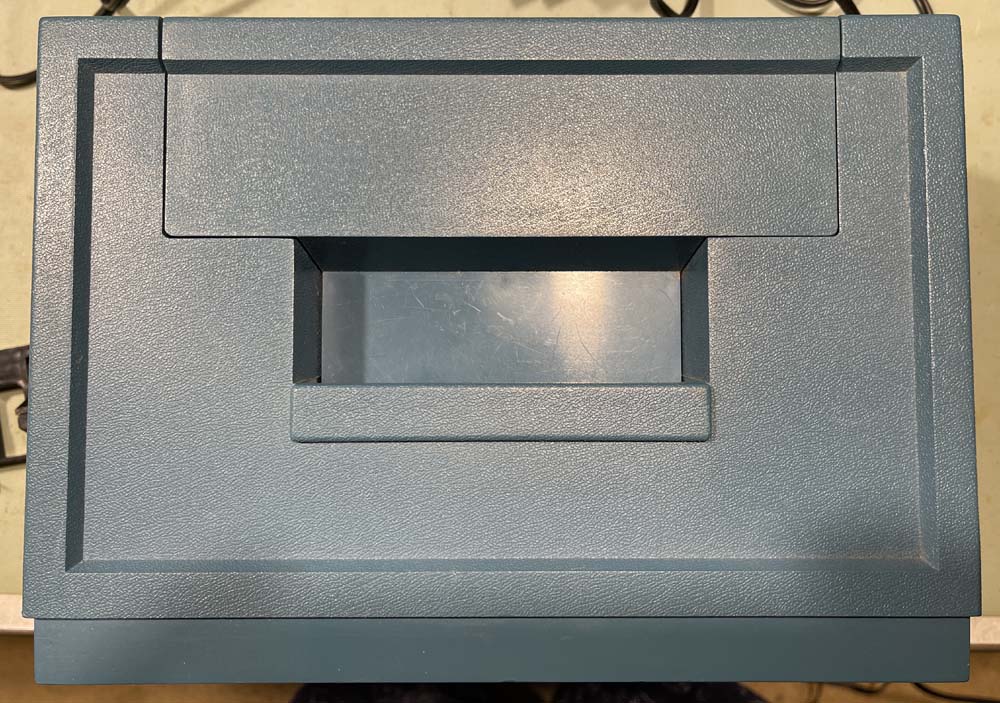
The top has a handle and a space that pulls up for cable storage:
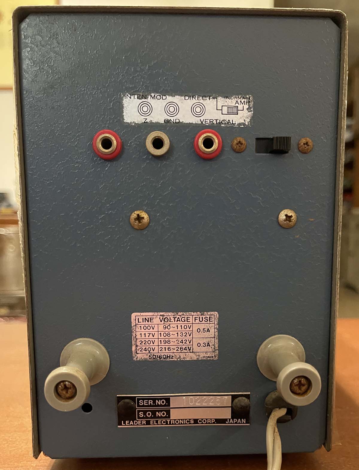
And the back has the power input.
The device requires +/- 9VDC, and can run on either a pair of 9V batteries - which you have to disassemble the case to get at - or an external power supply. Originally, this would have had a molex connector similar to an old floppy drive power input, but the previous owner removed it and added a terminal strip.
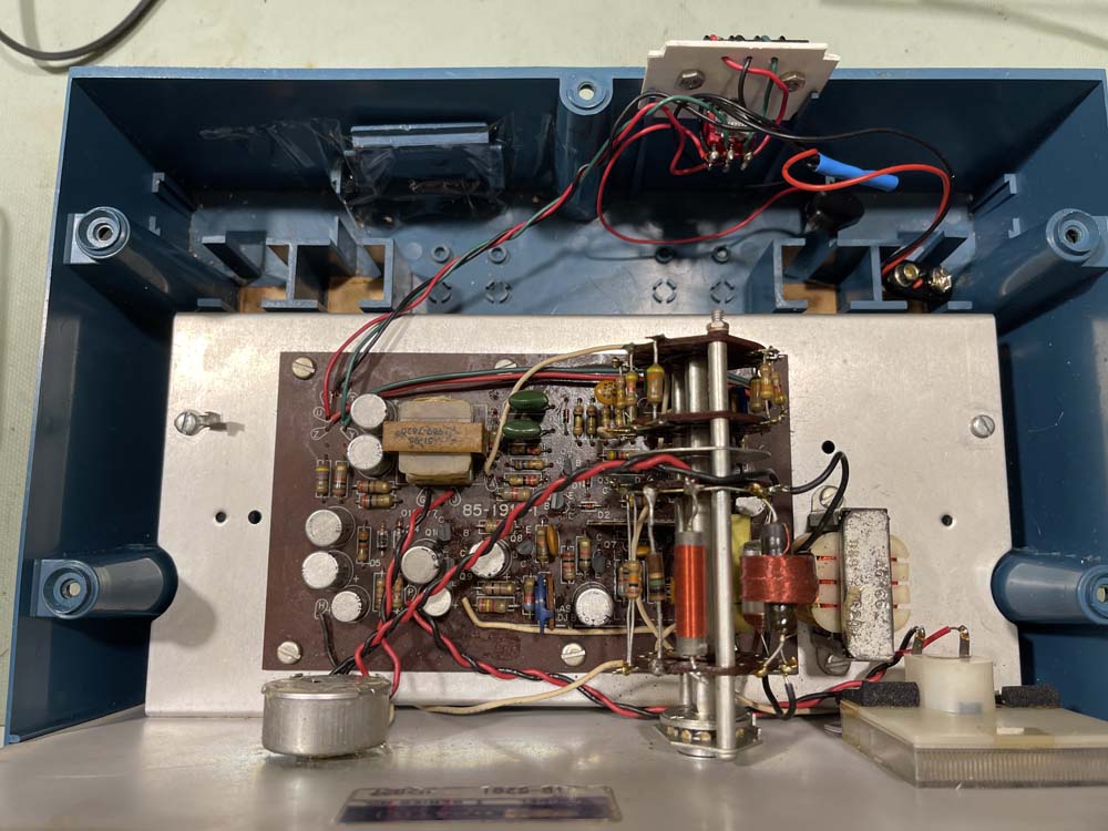
Inside of the device is pretty sparse.
A single board with all the components, the mode switch, meter, and value pot. The batteries go in holders at the back, if you choose to use them.
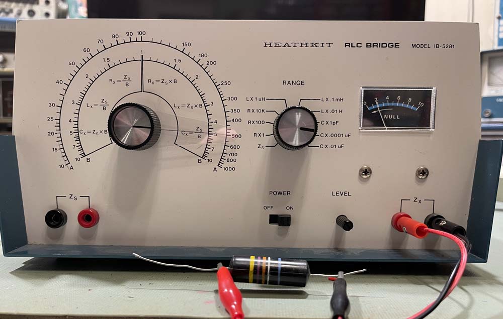
Let’s hook a part up to this and see what it does. I chose a bumblebomb from the Simpson 715 that is currently on the bench. It’s marked 0.047μF but reads about 0.052μF on my digital meter.
Lead length is important here. I tried these cheap long leads, but ended up having to rig up a set of shorter ones to get an accurate reading.
To use this, you:
Connect the unknown.
Set the range switch appropriately.
Turn the value dial as far away from the believed value of the unknown.
Adjust the meter level until it’s “10.”
Turn the value dial to get as close to “0” on the meter as possible.
Adjust the meter level control back up towards “10.”
Re-adjust the value dial to null again.
Repeat the above two steps until you can’t go up and/or null anymore.
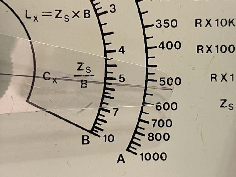
I ended up with this for the part under test:
So…it works as expected, even though I can see the level pot wearing out quick since you’re constantly adjusting it. I have to wonder why that control didn’t get a nice knob - that little plastic shaft is difficult to turn accutrately, especially considering that meter is quite unstable. Who knows.
I’ll probably keep this, just for the novelty, but who knows. You may see it and it’s brothers at a show near you.
In the last part, we started to replace some of the parts that are known problems in older devices. While most of these probably won’t do anything to fix the non-zero issue (and that is probably some other parts out of tolerance) - they will need to be replaced if this meter is going to go into service with any reasonable expectation of working.
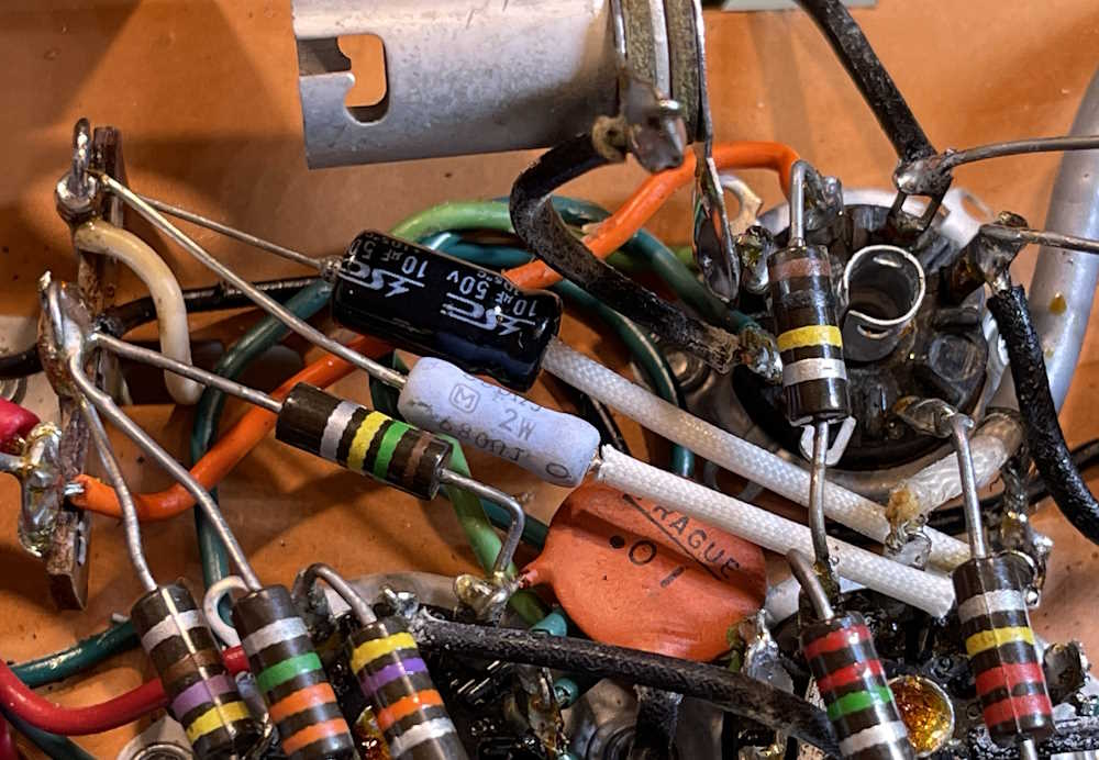
This part sees some of the components in the meter circuit replaced, and takes care of most of the (current) work on the bottom of the device. There’s a capacitor-resistor pair that we’re going to replace, and this is a component directly in the meter circuit. There’s also another resistor on the topside that’s part of this circuit, but that isn’t going to get replaced until later.
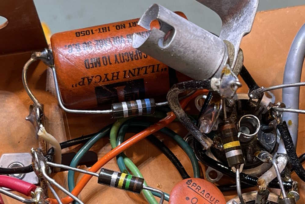
Here’s the components we’re working with:
In particular, the capacitor and the 2W 680Ω power resistor are being replaced. The 30Ω resistor is for later. The capacitor and resistor mentioned are soldered across one another, so removing the capacitor means the resistor gets removed as well.
I didn’t need to use a 2W part here, but that’s what I had on hand. It’s pretty much the same size as the old 1/2W carbon comp, so why not.
Here’s what we’re going to replace:
This part attaches to a terminal strip that carries a wire up to the meter board, and snakes down to a tube socket on the other side. They unsoldered fairly easily, and I was able to bend leads and remove the parts intact for later testing.
The new parts don’t need to go in the same way, they are small enough that they can simply run directly to the connection points with a little bit of ‘lectric sketti.
That was much easier than I expected, and I took the time to remove the filter capacitors as well. That’s next.
The old part was pretty much +100% at 1.4Ω ESR, so it’s getting tired.
Next up is the filters, then the meter board goes back on with some parts attached to it. Stay tuned!
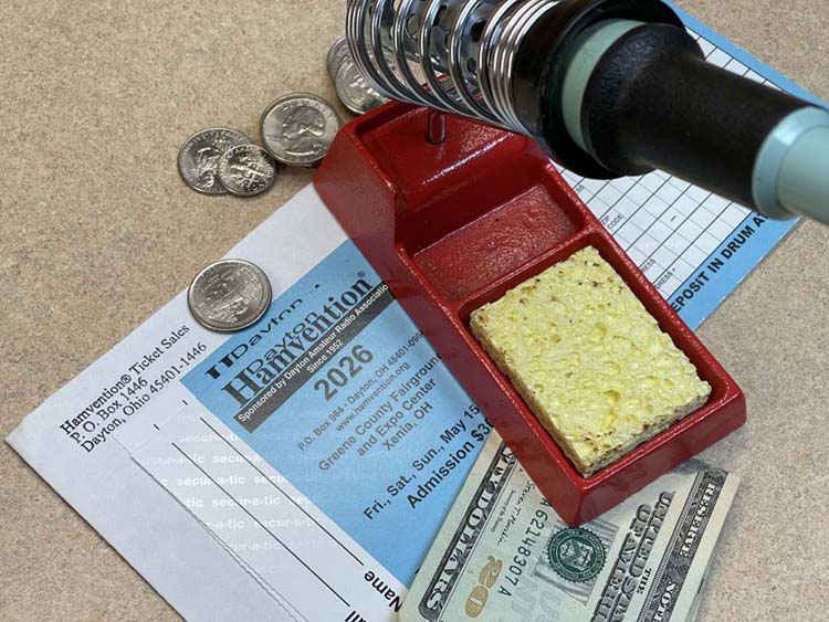
While still about 4 months away, there’s no better time to get your ticket as you can get the early boar price of $26, mailed to you at no extra charge. This is good for all three days - May 15th, 16th and 17th.
Ticket prices increase March 1st, so there’s no time like the present to get one if you plan on attending. Get your ticket here: https://hamvention.org/purchase-tickets/
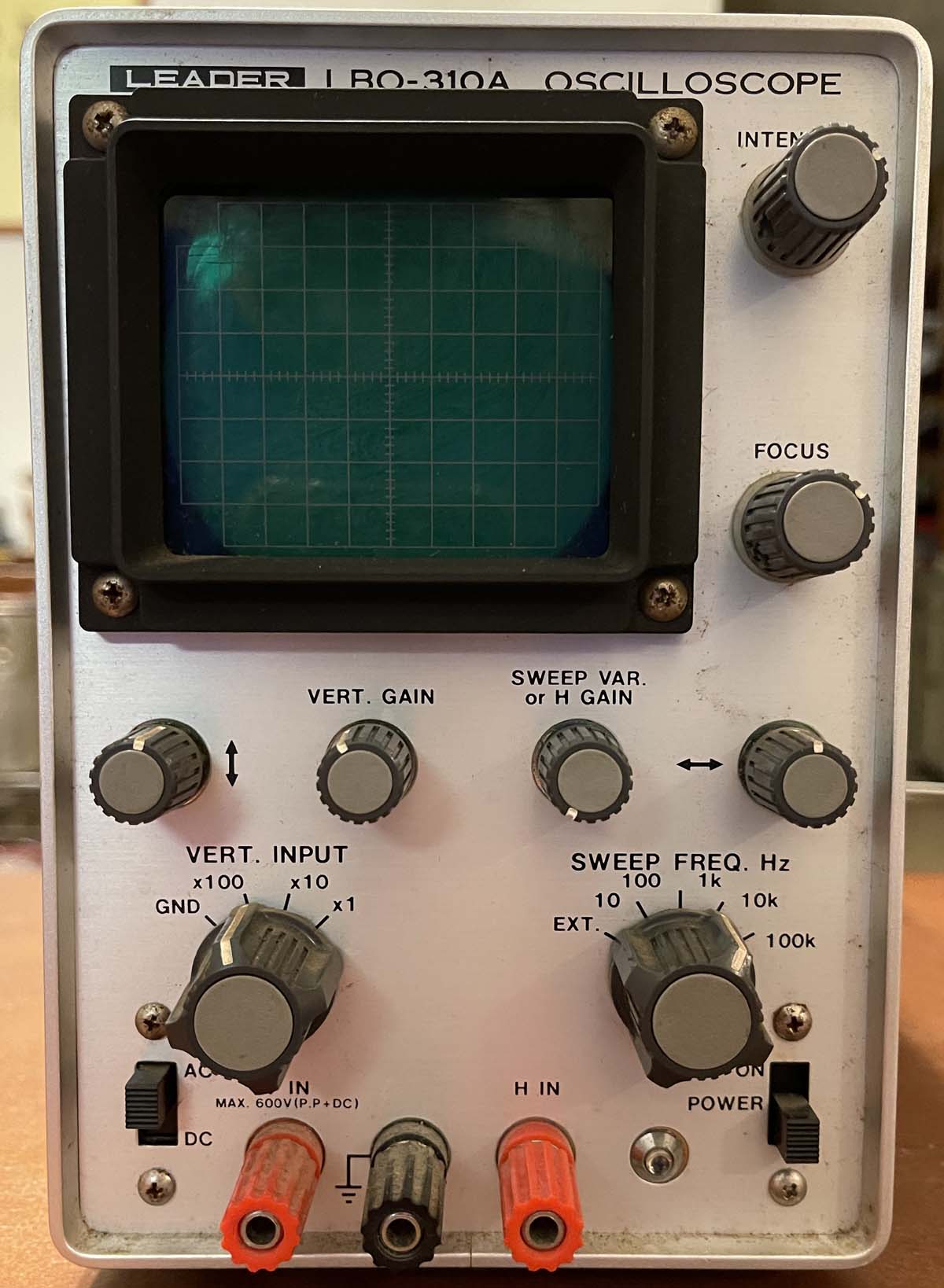
A friend picked this cute little scope up for me cheap because I’ve been looking for a small, actual CRT scope.
The Leader LBO-310A is a simple 4MHz scope that dates to about 1976. It doesn’t offer much except scope. Let’s take a look.
The device itself is pretty clean, both inside and out. The outer shell still has the plastic covering on the metal, so essentially underneath of this cover it’s brand new. Inside, there’s a little bit of the white corrosion that you get with this vintage of Japanese equipment, but nothing major. This scope was used, but not abused.
Even the cord is still good on this thing. This is one of the few devices that’s come across my bench that doesn’t need a new power cord.
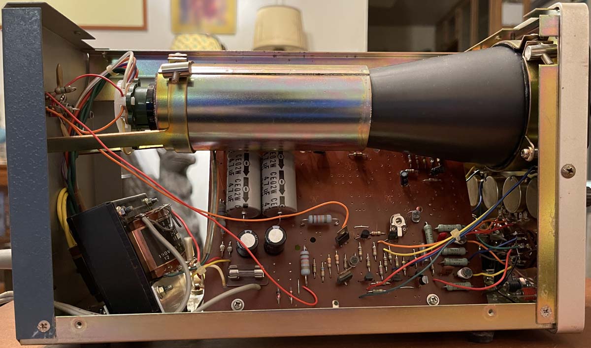
Inside is pretty sparse. This guy is transistorized, so no vacuum fire bottles except for the CRT:
There’s a lot of places for extra components, so this probably was used in other things, or had options that this unit doesn’t have. There is another board behind this one, that’s a power supply board - it’s not really visible unless removed from the unit - there will most likely be some better shots of that later.
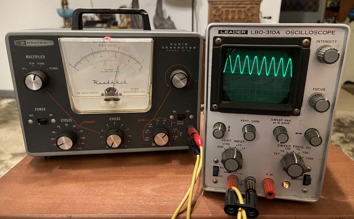
So - does it work? It does, that was demonstrated in the ad, but let’s try it out and see if it actually responds. First thing I notice is the pots are gooey and touchy, so it gets some Deoxit…in particular the vertical position pot is very touchy. More on this later.
I’m using a signal generator I picked up at Fort Wayne, a Heathkit IG-72 that I recently did a checkout post on. It needs a little adjustment but will work for this purpose. And yes, the device responds nicely.
The CRT is nice and bright, and the trace sharp. It does need a little rotation, so I’ll pull the manual and see which one of the internal adjustments does that for us.
The vertical position pot does have an issue - right about where it would be set for the trace to be in the middle of the screen, it’s dead. That’s not surprising, that’s probably where it sat most of it’s life, and I believe this unit came from a shop. That’s not a big deal, it looks about like one of those cheap Alpha pots that ratshack used to sell. I’m sure I can pic something up that will work here without issue, and I’ve ordered a couple of devices that should go in here without issue.
Stay tuned for the replacement!
In the meantime, here’s an operator’s manual, service manual, and a catalog page. The operator manual is in barely readable shape, but it’s there. https://wereboar.com … 0A%20Manuals.pdf.zip