This is a great mid-sized show that happens at the Butler Farm Show, an event area just outside of Butler, PA. There’s usually quite a few vendors, with indoor and outdoor exhibits. Rain kept last year down a little, so hopefully this year things will be a bit sunnier. There’s a food building on site if you want to grab a snack, and plenty in the general area of the show.
I’ve pulled some interesting things out of this show, and hope to again this year. See you there!
Breezeshooters Hamfest
Butler Farm Show Grounds
625 Evans City Road (Route 68)
Butler PA 16001 June 14th 2026
8AM - 2PM
$10 admission Click here for the show website.
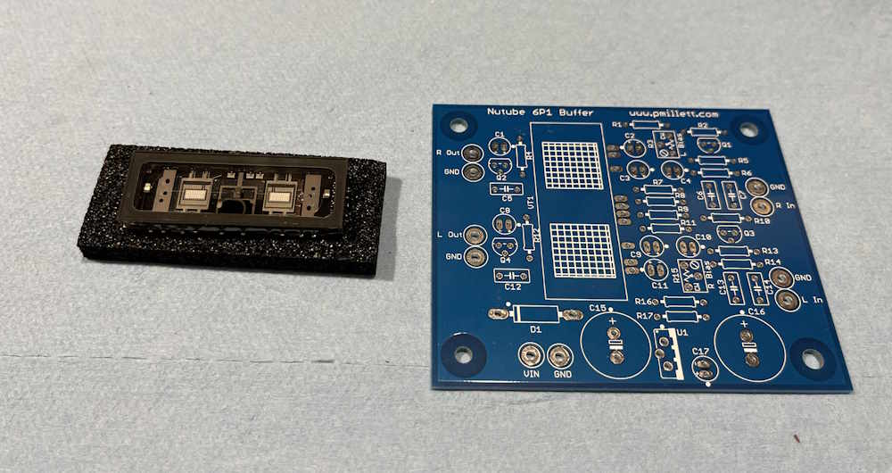
I’ve known about these devices since they were introduced a decade ago, but never really had access to one. I decided to get one to see how it works. There’s a seller on eBay that has both the tube and a PCB for a buffer amp, and I decided to pick one of those up. Here’s the good stuff:
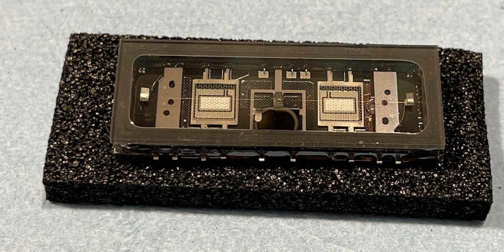
The device itself is kind of interesting - if you said that it looks like a vacuum-fluorescent display, you’d be correct. That’s exactly what it is.
What is this, exactly?
A vacuum-fluorescent display, or VFD, is a type of display that uses a filament, grid, and plate - just like a normal tube. The plate in this case is a painted substrate that is flooded with electrons, and this flood is either allowed or prohibited due to the charge on the grid. It’s and on-off device, but it still fulfils the basic requirements of a triode tube.
The Nutube takes that idea one step further. Instead of a painted substrate that’s a numeral or symbol, the plate on this one is just that - a rectangular plate that is flooded with electrons from a filament, modulated with a grid in the middle. It does glow in operation, but that’s not the point - this is a flat-pack tube that can amplify audio. It was designed, AFAIK, for Korg’s musical instruments because “tubes!” and because this device doesn’t need the high voltages that something like a regular 12Ax7 device would need - even though those higher voltages are trivially easy to generate these days.
The tube’s numbering doesn’t really follow standard conventions, but whatever.
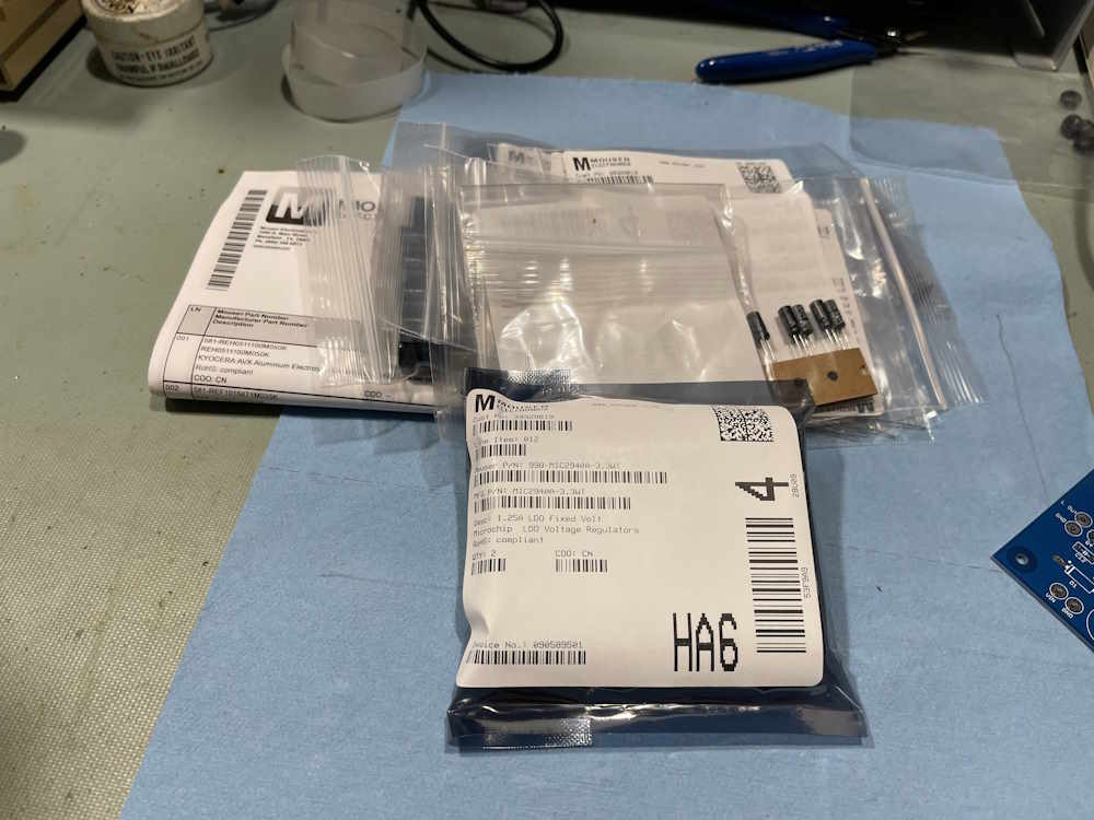
The vendor provides a BOM for this device’s board, but it’s out of date. I’ve created a new one and will post it as I build this device. In the meantime, I’ve ordered parts and hopefully will have time to assemble this device in the next few weeks:
Stay tuned for an updated BOM and assembly thoughts.
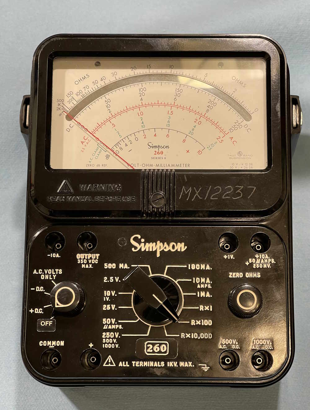
I had a request in regards to a Simpson 260 multimeter. I was asked if I knew what the handle bolt sizes are - I do not, but I decided to take a quick look to determine if there was anything of use easily visible. I have a series 8 available, so I said I’d take a look.
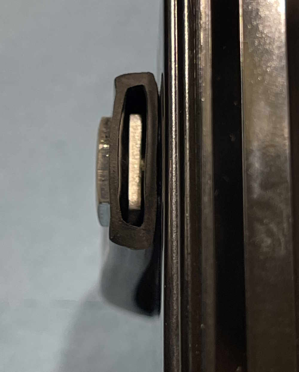
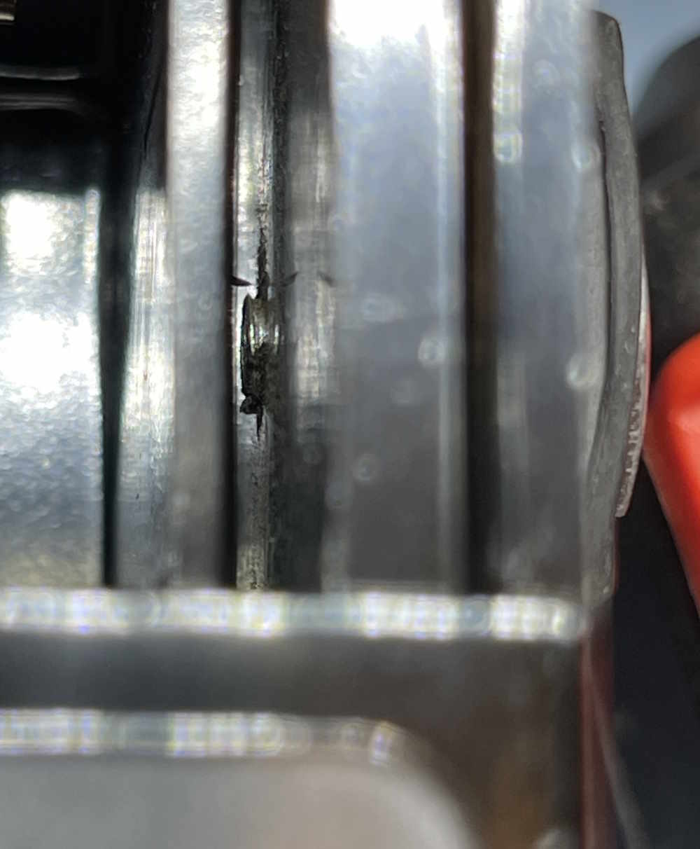
The first thing of interest is the handle itself. The handle is held on by two large hex bolts with a thin head. These bolts pass through the handle. Inside the handle itself is a piece of metal. This metal pivots with the handle, but doesn’t necessarily appear to be part of the handle.
The bolt then passes on through the case.
Unfortunately, I can’t get this apart to measure the end of that, I suspect these have to come out before the meter assembly pulls from the case back.
That’s all - this was just a check of some parts on the unit. Stay tuned, more good junk on the way!
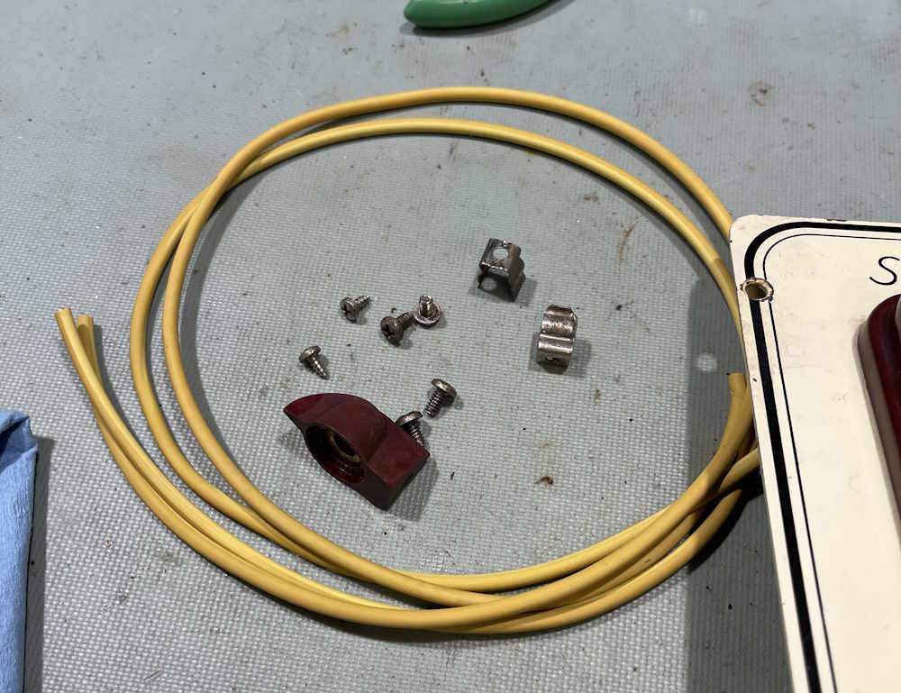
This device was an easy fix. Some wire, a couple of probes, some grommets - and we’re done. Cable is even color-matched to the unit!
I scrubbed the case down, and gave the switch a spray of Deoxit as a preventative, even though whatever the OEM used was not really tarnished like other switch rings I’ve seen.
So. Does it work?
Sure does! The new battery reads as a new battery.
That’s all for this device, it goes on display until needed. Stay tuned for more EICO 950A goodness!
Working with this unit has been interesting, especially with the original problem of being a shorted speaker. But, for now at least, the unit is operational but still has some issues to solve later on.
What’s going on?
After the speaker replacement, there was simply a lot of noise. half a volt of noise, to be exact. This was unacceptable, and there were two potential causes - the transistors, which most say to replace with the capacitors, or the carbon composite resistors.
The transistors helped considerably, but only Q3 and Q4 - this reduced the noise levels to about 1/4 of the original, as received value. That’s pretty good, Q4 was noisy and replacing it with a (not really much newer) transistor cleaned that up. The rest, unfortunately, it probably coming from resistors and I’ve read posts indicating that metal film resistors here help considerably. That will be another project later in the year.
Beyond that, I changed the meter drive level. The meter on the front is simply a mechanical version of an eye tube. That is, it’s not calibrated in any way, it’s just deflection. You really had to drive the thing hard to make it move, and I wanted that to happen at a lower input. Paralleling a resistor with the input resistor has allowed that to happen, and it’s placed as such it’s going to be easy to remove should I or a future owner want to bring it back to spec.
Anything else?
There’s nothing to say other than to pay attention to your replacement transistors. Leads aren’t always the same from part to part!
In the last part of this series, I put some new transistors in the device. And had to replace them once again because they were inserted incorrectly.
With that being fixed, it’s now time to check the unit for actual operation, make one final mod, and see what we have. Here’s the data:
What the manual says:
What the old transistors said:
What the new transistors said:
And finally, the noise levels:
The noise is very similar to what we saw after Q3/Q4 replacement, so the previous transistors, while providing the noise, don’t seem to be causing it. Some commentors on the youtube videos suggested the resistors are probably doing it, and I tend to agree. Old carbons are noisy.
The transistors also show some improvement in voltages, especially Q1 and Q4. Q1 should be off when measured in this configuration, and it is. Q4 is now closer to the Vdd rail, as it should be. Current draw on Q4 has also reduced, but is still high - probably because it’s amplifying noise. We’ll see what resistor levels do to that.
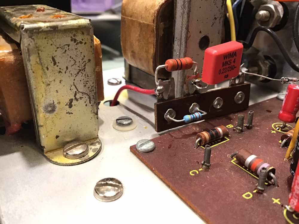
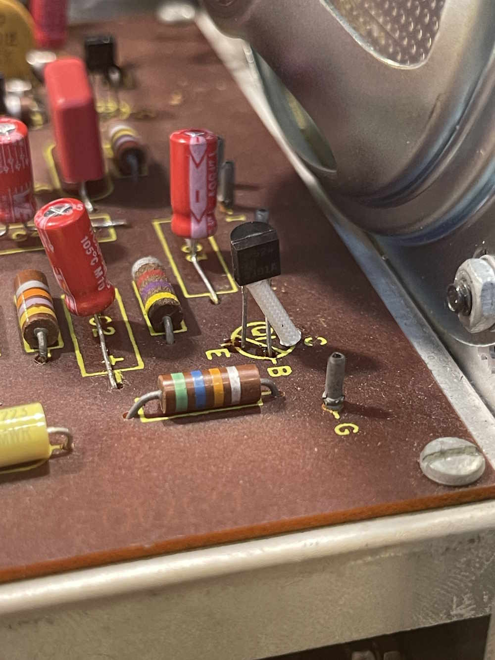
The final piece is to change the meter level. You really have to drive this thing hard to make it deflect, and I don’t want that. Calculations made during a forthcoming video suggested something around 3.1kΩ would make the meter happy. I accomplished this by paralleling a resistor with the 10kΩ input, and that resistor turned out to be around 4.7kΩ. It was stuck into the holes in the terminal strip so a future owner can easily remove if needed.
With that, this project is finished. I’ll probably start a new one later to swap out those old carbon resistors - but for now, that’s all and the device is working well. There’s one more post for the wrapup, and please check out the YouTube playlist for this device.
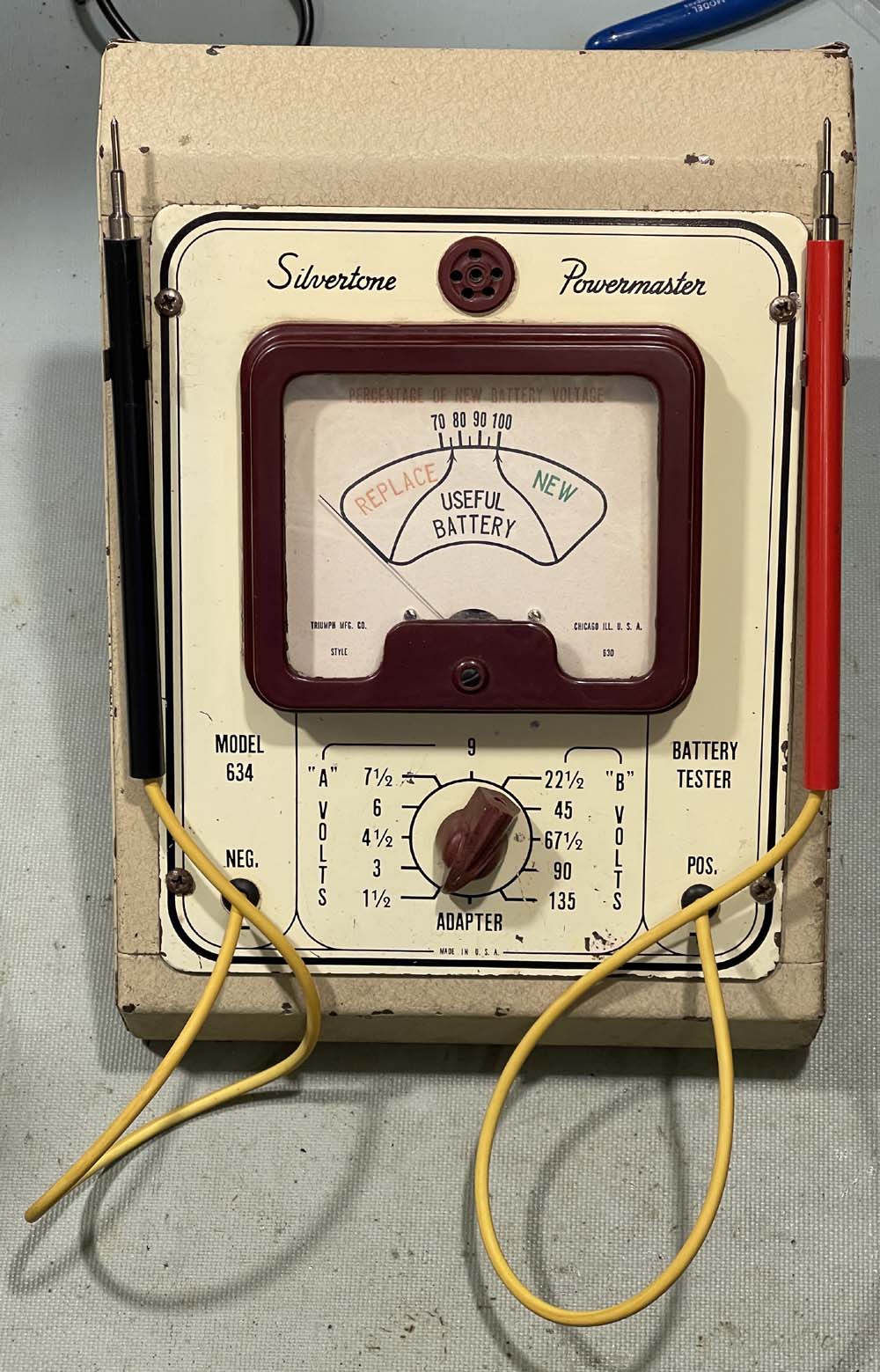
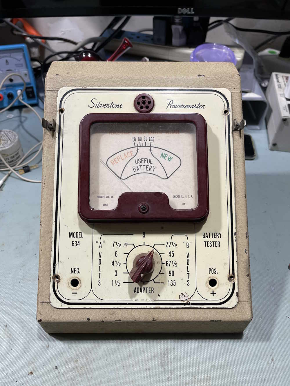
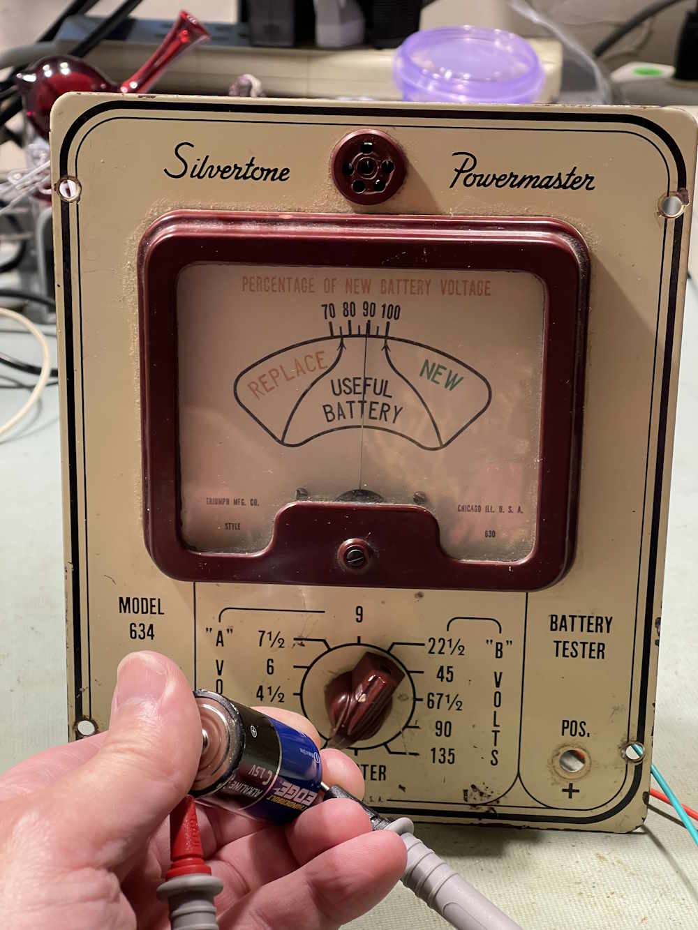
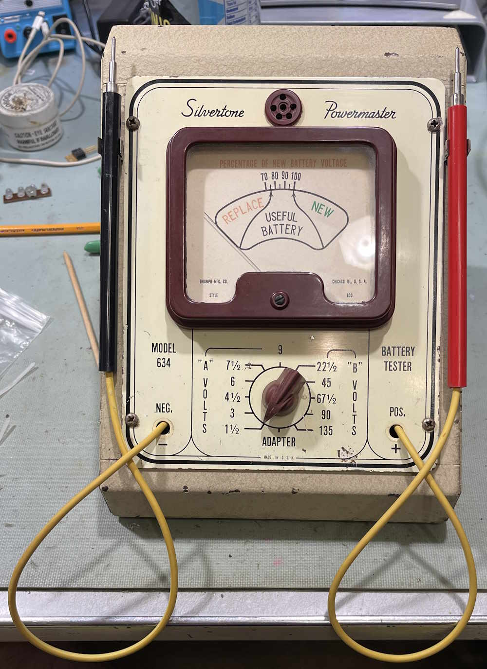
This is an interesting piece of radio history. Originally seen at the Findlay Hamfest in 2024, it showed up again in 2025, at which point I made the vendor an offer and took it home. Silvertone was the house imprint of Sears & Roebuck, once the “everything by mail” store in the USA. Sears expanded into physical stores, and devices like this unit would be sat on a counter at the radio department so you could test your batteries. Sears, of course, would be happy to sell you new “Powermaster” brand (another house imprint) batteries if yours were depleted.
The case itself is in ok condition, but it appears to have had some water ingress at some point. You can’t really see it in the image, but there’s some rust near the front of the slope. Note the two fuse clips near the top, those would have held the probes.
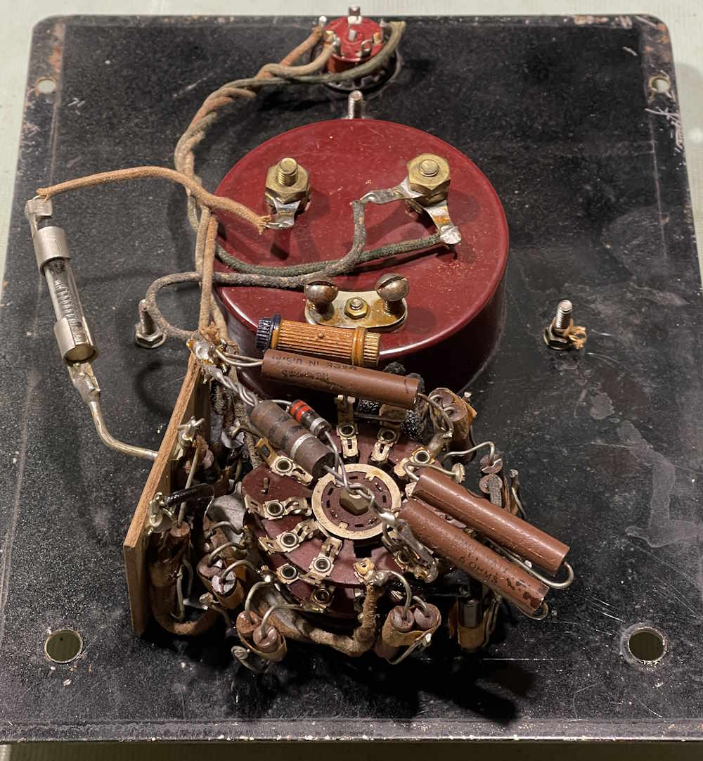
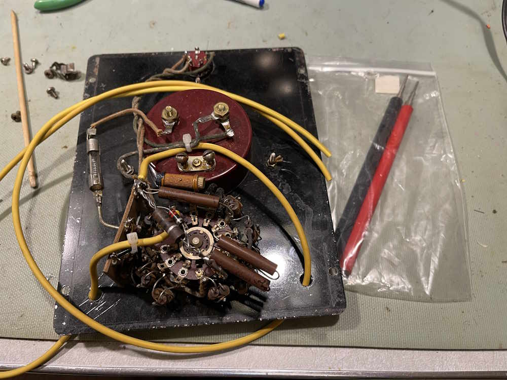
This is nothing more than a simple load tester, and is full of resistors to divide the voltage down for the meter and provide some load testing for the battery you’ve connected to it. It’s essentially a specialized voltmeter.
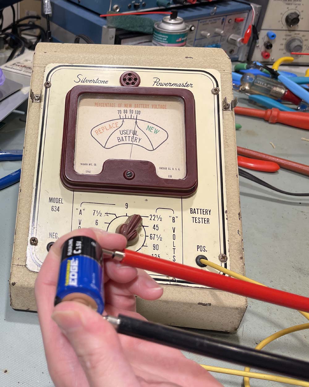
Before we go any further, does it work?
Sure does, this new battery reads decent on the unit. Probably will work a little better once probes are re-attached.
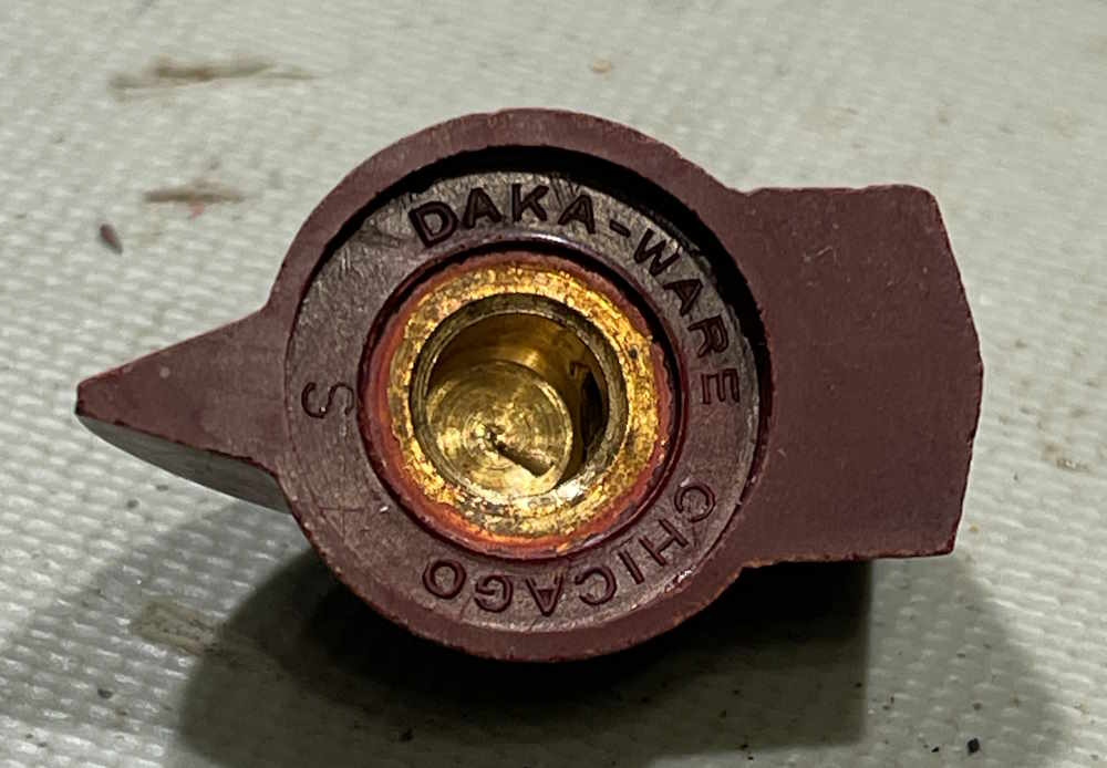
Of interest here is this knob. It appears to have been made in Chicago, and may have been sourced just for this device by Sears. After some research on this, the company, Davies Molding, appears to still be in business!
I have some cable and probes for the unit. Both of those were probably purchased at Mendelson’s Surplus many years ago, for far less than you’d get them today…I do miss that place.
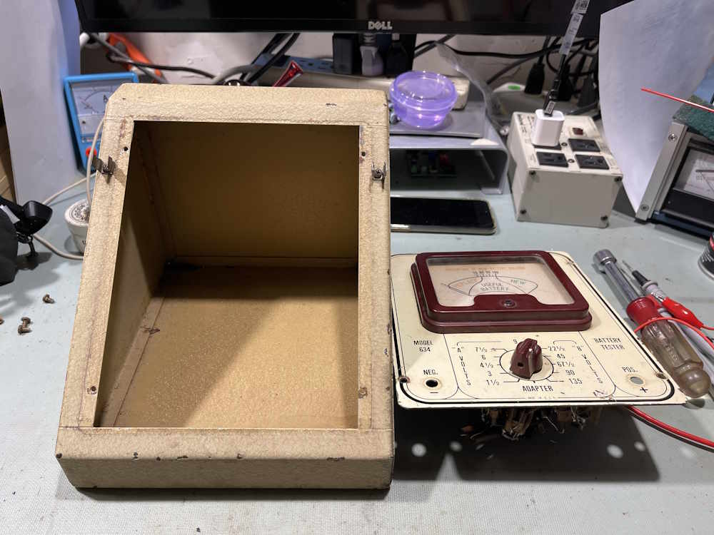
It took a hot minute to figure out where the leads went, but after some investigation I determined that the negative goes to a big mass of resistors, and the positive goes to a terminal that has a second piece of phenolic on the switch. That one became obvious when I examined it with a magnifying glass and noticed it seemed to be a bit shinier than the rest, indicating it had been disturbed at some point in the recent past. Makes me wonder, did this thing have probes on it until recently and someone wanted those vintage pig pokers? Don’t know…
There’s still a bit left to do, I have some grommets on order for the holes and still need to solder the probes on, but this is what it will look like - eventually…
Stay tuned, this thing is going to work again soon!
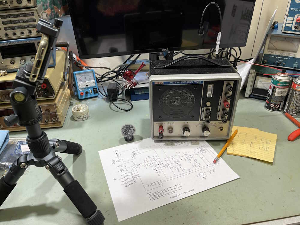
Last night, I sat down with the EICO 150 and started to do the final wrapups on the unit.
Apply a signal.
Nothing.
Excuse me, what?
I focused on the function switch, but it seemed to be working properly after some study. I was able to put a signal in after Q1, and have it work, so that really threw me. I was able to bypass the input blocking cap on Q1 and get more signal, but highly distorted. So what’s going on here?
I decided to try the transistor(s) I pulled out for Q1 and Q2, starting with Q1. Removed the new Q1 and just tacked the old one back in. Immediate signal improvement. A check on the new Q1, and it’s just a diode now.
I get a new transistor for Q1 and check it. It’s good…and there it is.
Leads. The pinout on the transistor is different than the OEM unit.
I replace Q1 and Q2 (which is also a diode now) and I have output loud enough to make your ears bleed.
Rookie mistake. That’s on me. Always check your parts, and pay attention to what your tester is telling you.
Next post is actually doing the final tests I wanted to do, and to try and change the sensitivity of the output meter a little. Stay tuned!
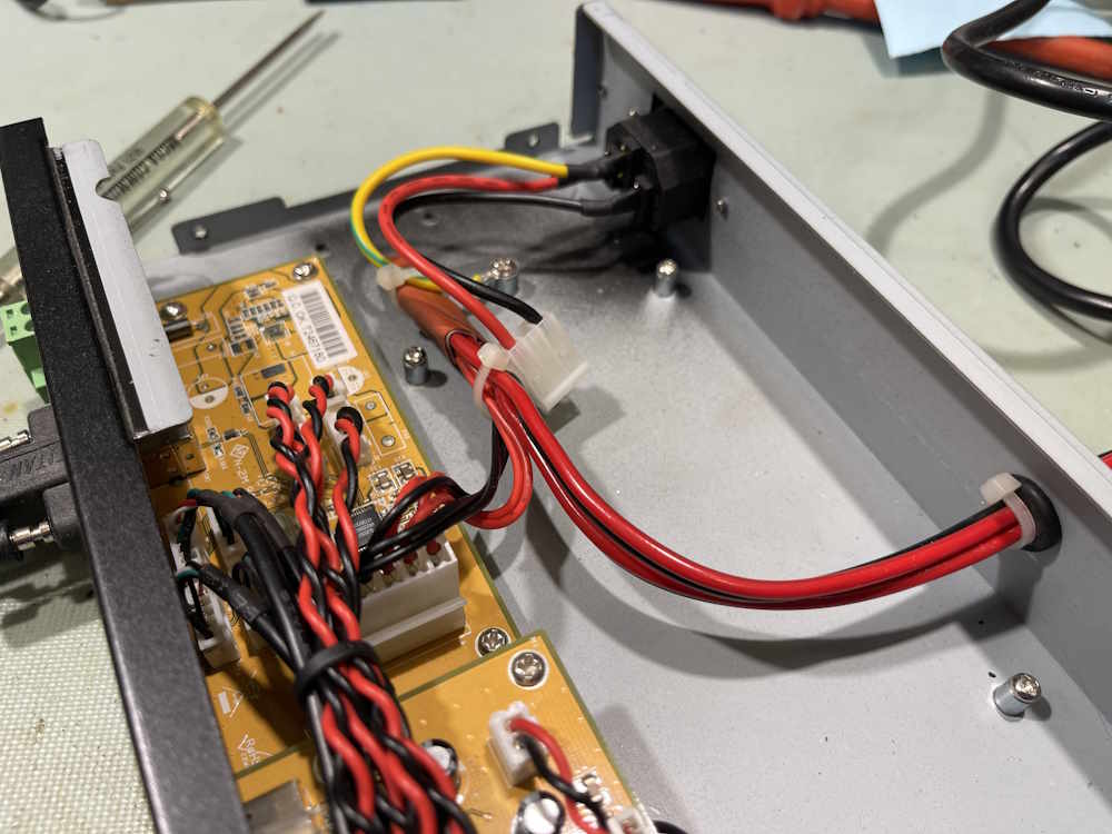
I’m not sure why I didn’t run that lead behind the other one, instead of in front. Who knows.
About a decade ago, I interviewed at a small company in a large town. They wanted a tech, and called me via a recruiter. They wanted me to do a test, which I declined at first, but eventually said “yeah, ok, why not.” It was a basic electronics test, and I passed 100% with one question that we had to discuss. We eventually came to the conclusion that yes, their document was rather poorly copied and my interpretation of the symbol used was acceptable because it looked like that.
The interview went well. I was able to competently talk to them about products and technologies, about what they were doing, and how I could possibly integrate myself into that. They stated that if I wanted to explore other avenues of experience, like PCB design or circuit analysis, then they were more than happy to allow that. It really seemed to be a good fit, and I went away feeling good about the interview and my prospects.
A few days go by, and I’m called and offered the job. I’m told the pay rate - base is a few cents more than I made at the time, but that’s not worth the longer drive and hours the company would need, nor did it take into account other payments my current employer gave (and had given) for many years, payments that I could reliably count on and they offered right up until the day the owners had to retire because they couldn’t do it anymore. Things I had mentioned during my initial screening with the recruiter. I was being offered about $1.70 less an hour for this job, and it didn’t include that this company had a higher insurance premium.
I turned it down at that rate but said can we talk about that? No, that was the offer. Take it or leave it. I left it. There was no arguing, no crying, no nothing from the employer. Not even a chance to negotiate. I did end up speaking to the employer a few months later when some things changed in my situation, but they were frosty. No problem, I understand, thank you for taking the time to talk with me.
Fast forward to 2025. A friend and I are going to a hamfest in Southern Ohio. This guy knows people at the company in question, I believe he went to school with some of them. He had done some consulting work for the company, so he was familiar with the people and the owner and talked to them at times. For some reason, during our drive the company came up as in they didn’t offer anything. I can’t remember how we got started on that but this is something on how it went:
Friend: They were mad when you turned that down.
Me: What do you mean?
F: Just that, they were totally p**sed that you didn’t take that job. They were mad. You were their guy, and when you didn’t take it, it really made them angry.
M: I was their guy?
F: Yeah.
M: You know why I didn’t take it.
F: Yeah, it didn’t pay anything. I told them that too.
M: What did they say?
F: They said “That’s what this job pays.”
M: Really?
F: I told them “Well, that’s just not enough, is it?”
The conversation kind of continued along the fact that friend couldn’t get them to move off that “this is what we pay” line of thinking.
So I was their guy, but “that’s what the job pays?” So even if I wasn’t their guy and was just “Hey, I think we can work with him” I’d get the same amount? What? I don’t understand that. I was ready to step into that role, but the company was just “Well, we have a set rate and it doesn’t matter if you’re the god of your discipline or if you’re just some dude.”
It’s probably for the best that I didn’t take that role. It would have been a lateral move for the most part, with company conditions essentially trading like-for-like. It probably would have been interesting, but I wasn’t willng to take a time and pay cut for the job at the time, even though I think we might have been able to work together later. So there’s not many tears shed here, just a “Hmm. What if?”
But the thing I still can’t get over is that attitude. Why even bother if you’re not going to negotiate for the things you want? Why not tell me this up front if you have a set number already chosen? I would have said “No, I’m sorry, I make more than that and we shouldn’t waste our time,” but…time was wasted and people got mad, all because “their guy” decided that being that guy didn’t pay enough - or even what he had at the time.
C’est la vie. Life moves on and we learn what to ask and when. I know they hired someone, but I wonder if they learned what to ask.
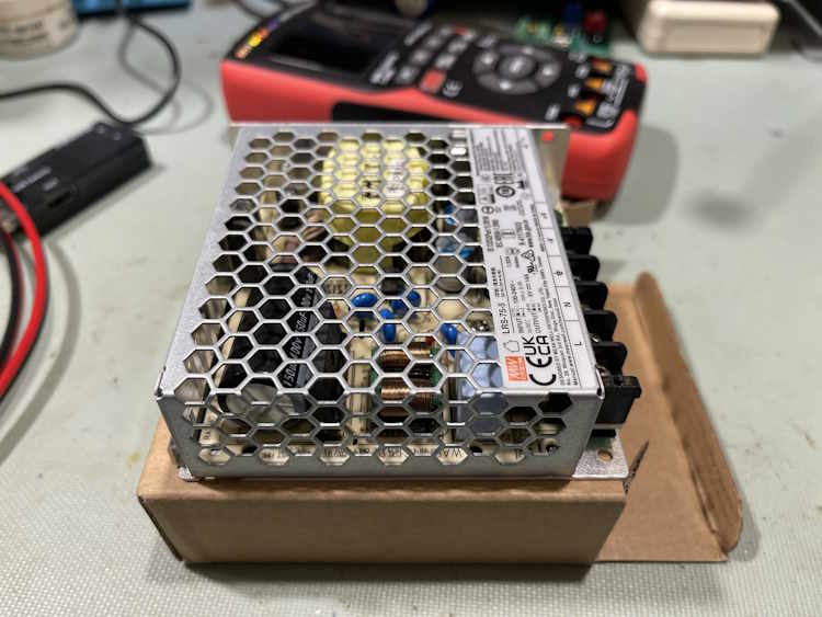
This device sat in my rack for many years, both providing power and USB services for various things. It quit back in March, the power supply giving out like switchers do. You can find that post at the bottom of this one.
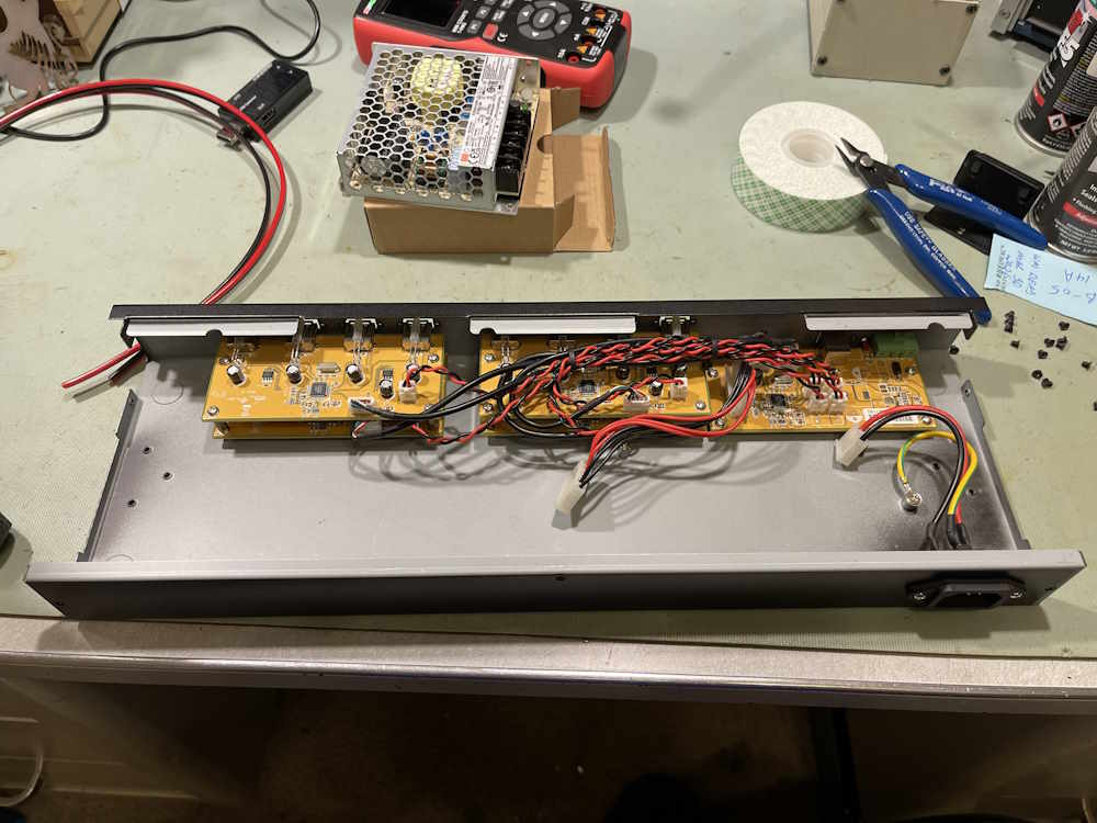
I was going to simply toss the device in the recycle bin, but…high current switchers are so cheap these days, there’s no reason not to fix it. So, let’s open it back up:
I wasn’t able to get an exact replacement for the supply, so I got a MeanWell equivalent unit. It won’t exactly fit inside, so we’ll make do.
For this task, I drilled a hole in the rear of the chassis and connected the new supply lines directly to the input of the hub using some good 16GA wire. I probably could have used a single strand here, as the internal wiring was somewhat lacking in size - but I used two, because just in case. They’re soldered together, and covered with two layers of shrink tubing.
The other ends were stripped, terminated with an aglet, and screwed into the supply, which now sits on top of the hub chassis. Open frame devices like this aren’t something that I’d put in a place where others could touch, but for me - it’s fine. The hub is back online and working.
There’s a youtube video for this device: Coming soon.
I’m happy that a piece of what could be e-waste is now back in service.