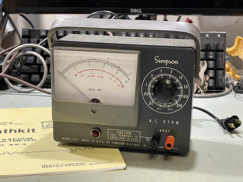
A Simpson 715 AC VTVM Part 9: Wrapup and final thoughts.
Wednesday, April 1, 2026 at 07:28:26
The Simpson 715 is still somewhat of a mess, but I knew that going in. With almost any meter of this age, the resistors in the divider ladder are going to be way out of tolerance. While I didn’t measure any of them, voltage testing suggested that it starts at the bottom - so yes, literally all of them are probably bad.
I’ll revisit this device later, but right now I have other things I want to work on, and determining what resistors are going to be needed will require some thought.
This device didn’t have any real data about it, so I wasn’t sure what anything was supposed to be - plate voltages, tube voltages, etc. Fortunately, Simpson made this unit for Heathkit as the AV-3 kit, and Heathkit’s manual for the device was their normal, packed full book. All of the information was there and that helped considerably.
The original problem I was trying to correct.
The original issue with this device is that of no zero. While the device still doesn’t necessarily zero like I think it should, it’s much better than it was. I suspect there’s both some resistors bad in the unit itself, and that the meter movement may be a bit flaky from being beat around over the years.
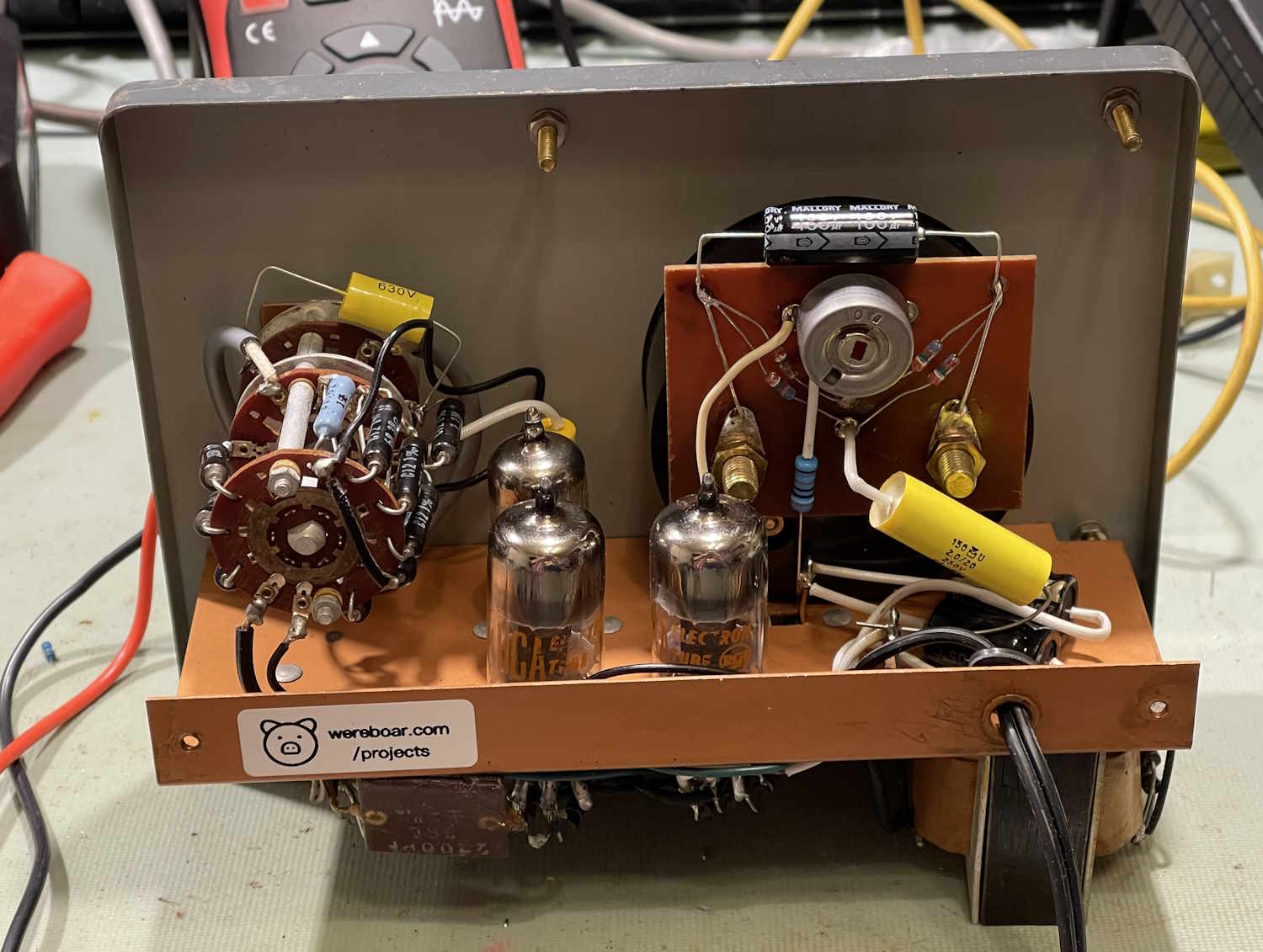
As this was a piece given to me by a now-departed friend, I wanted to at least make sure it did something, and that it does. For the most part, I simply replaced all of the capacitors in the unit as they were old wax paper, bumblebee, and other assorted relics from a bygone age.
That was very straightforward and didn’t incur any issues.
The Selenium Rectifier
The selenium rectifier didn’t really present any challenges save that it stopped working midway through my testing of currents in the circuit. This required some guesstimations, which were incorrect. I was eventually able to determine was the device wanted after some physical experimentation.
That experimentation involved going back and making a new guess based on some other real-world devices, and getting it correct. I wound up with a 1.27K resistor replacing the selenium stack, bringing both of my B+ values to within 0.5V of the rated value.
I had posted about this device elsewhere, and had someone tell me that I was doing this wrong and making it harder than it needed to be. They read online that a selenium device only has this much drop, and that I should simply use that information to design a regulated supply, hope that helps.
No sir, that didn’t help. Sorry. But if you have a regulated 130VDC/120VDC power supply that fits in a selenium stack space, please let me know.
Final Thoughts
As I said earlier, this one isn’t done - especially if I want to actually use it. It’s a cute little device, so I’d like to - but the meter movement itself raises some concerns. I’ll definitely revisit this later, but for now - it’s mostly operational, and it’s good to sit around for a while.
Next up is an EICO 249 that has a similar issue, that of the divider ladder being bad. I have a spare unit and can rebuild the ladder assy out of parts, on the bench. Stay tuned for that one.
The complete Simpson 715 rebuild series.
A Simpson 715 AC VTVM https://wereboar.com … simpson-715-ac-vtvm/
Fixing the no-zero issue? https://wereboar.com … x-the-no-zero-issue/
Capacitors, of course. https://wereboar.com … acitor-replacements/
How did this work? https://wereboar.com … t-4-filters-and-wtf/
Testing the repair. https://wereboar.com … -testing-the-repair/
Intermission. https://wereboar.com … part-6-intermission/
Selenium-ectomy https://wereboar.com … -rectifier-replaced/
Final checks. https://wereboar.com … part-8-final-checks/
Wrapup: You’re reading it now.
Previous part of this series: https://wereboar.com … part-8-final-checks/