I’ve been slowly going through this device, checking parts because the output seems very low and distorted. I can overdrive one of the interstage transistors with not much input, there’s something wrong.
Here’s what I’ve come up with:
1. Leaking coupling capacitor. Unlikely, in my opinion, because the voltages here are pretty low.
2. A resistor or other part has simply gone bad. Possible, but I checked resistors and while some are out of tolerance, none are what I would consider terrible for a carbon composition resistor.
3. There’s a wiring error present.
Let’s focus on #3. After going through the unit, verifying what I could, I started checking bias on transistors. The bias on the final output should be 0V at the collector.
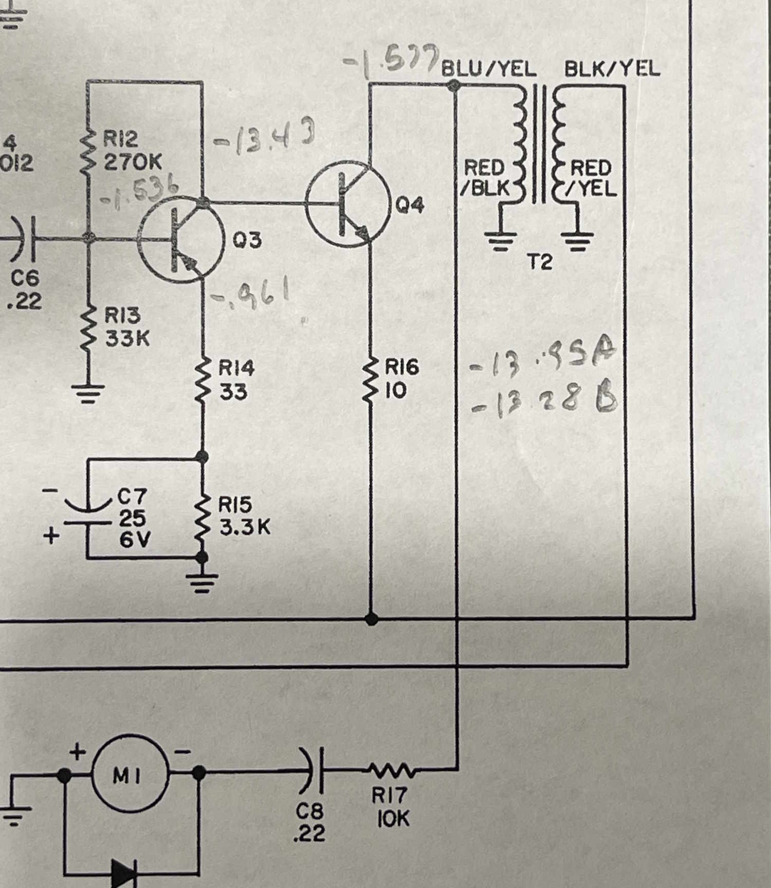
Here’s a schematic of that final output, Q4, and the output transformer that couples it to the speaker:
I have -1.577 noted on the collector. That’s not right, it should be 0, or very close to it as there’s no DC resistance on the input side of the transformer.
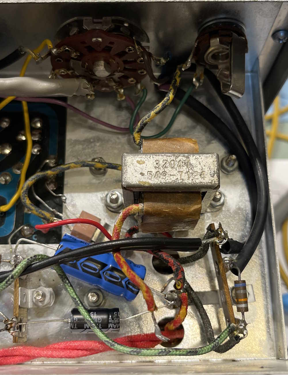
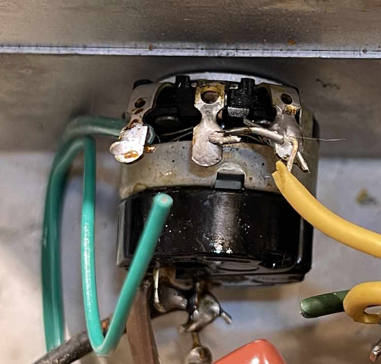
Now…note that there are two sections. One is identified by a Red/Black to ground, the other, Red/Yellow to ground. The input sides are also differently colored, but they don’t really call attention to that in person. We’ll get to that later.
You can probably guess what happened, and there was something in the back of my head going “The output isn’t right, but I don’t know why. Check that closely.”
The original builder connected the 16Ω speaker output side to the transistor. Not only was it trying to drive a 0.7Ω load into a 16Ω speaker, the output transistor was trying to drive into the wrong impedance. I’m really surprised it even worked, and it may explain why the output was driving excessive voltage into the transformer. Fortunately, the transformer seems to be good…I hope. There is about 15MΩ of leakage across the windings, but that could just be normal for this guy.
While I haven’t changed the order of the wiring yet (probably going to require some wire stretching,) I imagine this will probably help the output levels substantially.
Why did they do this? Well…
1: They didn’t bother measuring and didn’t pay attention to the colors on the Yellow/XXX (and to be fair it’s very difficult to differentiate in person, the camera reveals more color than the naked eye does,)
2: They wanted to use the higher impedance input side as an output for high impedance headphones.
I’d guess #1. Well, yes…but no.
I measured the connections with a meter. Yellow/Black and Red/Black are connected! The transformer was made wrong. The person that wired it wired it properly based on the colors. It worked (poorly) so they just assumed it is what it is and moved on! I wonder if that had anything to do with the problematic transistor repairs early in it’s life?
Maybe not?
The transformer, while wired wrong, was probably installed correctly. It’s been so long since I’ve worked with this kind of device that I don’t have any reference these days. The primary should be low ohms, and the secondary should be quite low.
When I measure the 8 ohm speaker, it’s shorted. That’s probably the issue. I just need to get hold of an 8 ohm speaker, and rat shack isn’t there for me anymore…
I made the changes to the circuit and it’s worse. But the speaker is certainly a problem. More troubleshooting to come.
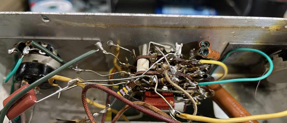
There’s not much to say here other than this thing is a mess. The person doing the rework was persistent. Not good, but persistent.
I wondered why all of this was done, but then found a piece of the original wire buried under some crap. It’s very thinly insulated, almost a couple of woven strands of thread and just disintegrates. If that’s what this was wired with, it probably lost most of it’s insulation. Still no excuse for the way it was done.
I’m going to present some pictures here. Some may have a blurb, others may just be before/after sets. There’s probably going to be a few more of this type of post since everything needs redone…
Rework pictures
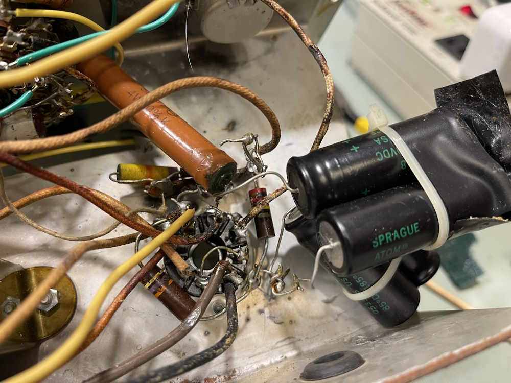
Even some of the original parts, like the big 500Ω resistor, were cut and resoldered. Barely. I’m going to simply remove everything in the power supply and rebuild it as a unit.
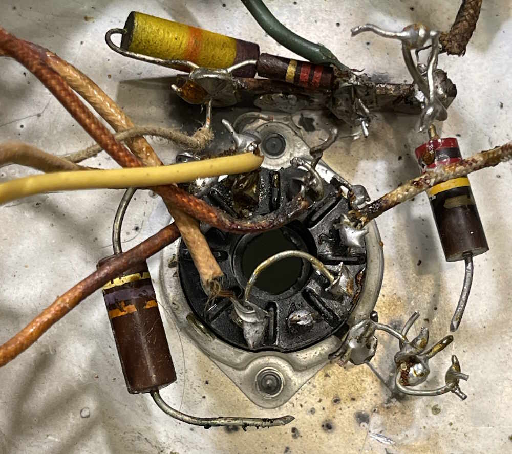
The Hall of Shame
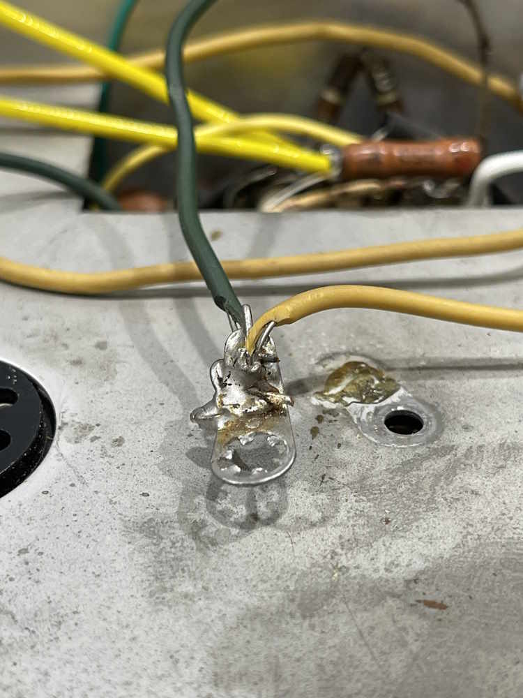
So. Many. J. Hooks.
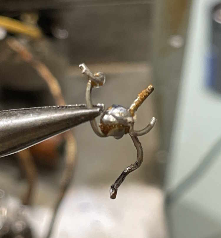
I’m surprised this worked. It’s more oxide than metal.
This electric spider was hiding in the power supply.
If you want to mail order a Dayton Hamvention ticket, now is the time! You have until May 1st, after which tickets will be held will-call at the gate. This is for domestic orders, international orders are being held will-call right now.
Mail order ticket sales have ended. All sales are now will-call.
This device has a lot of little capacitors all over the place. Interstage, coupling, bypass, etc. There’s even a multi-section filter array underneath. Most of the small ones were bad, as in >90Ω ESR bad.
Replacing the capacitors in the EICO 150
Here’s what we’re working with. This is a “Type 1” assembly, and has a mix of topside and bottom chassis parts:
I decided to go with all good stuff here. Small capacitors are Wurth, larger ones are Vishay or IC. As this is a single sided board, it was easy enough to heat the joint, pull the part, and then clean up the pad with some wick. New capacitors were bent as to provide leads to each pad, or folded over as needed. Parts on the bottom were simply patched in place of the previous part.
The ones that were really bad were all of the little 1μF 15V parts. Every one of these was well past useful with ESR measurement. Some of the larger ones were tired, but ok, with the filters being acceptable - although appearing to have been replaced at some point in their life already.
Every capacitor in here that’s an electrolytic has been replaced. I did a quick check on those teal blue ones, as I’ve found those to be shorted in other EICO devices. These seemed to be ok, but it would be best that those get replaced as well.
Testing the repair
The gain is certainly much higher now - 1KHz test tones are loud enough to damage your hearing. I tried a radio source, it doesn’t seem to have enough gain here - but that could be impedance matching isn’t very good, as the radio’s drive is nothing more than the low-level output of the demodulator IC itself. I need to look into this a bit more. There’s also some wiring I want to clean up in this unit, just because it’s not tacked together well. That will come with the other capacitor replacements.
It works, and is probably good enough at the moment. We’ll get come back to this one soon enough.
It’s not good enough and has some transistor biasing issues, as well as some WTF from the previous owner.
Notes
The transistors this thing uses, or can use:
2x 2N3391A. - These are generally obsolete, but can still be found easily enough.
1x 2N3906 - These are common as dirt.
1x NTE152 - This is the final output and is becoming scarce, although is still available.
If you have one of these devices, it may be wise to stock a few of the obsolete parts.
Recently, I decided to dip my hooves back into the cesspool that is YouTube. I’ve tried this before and failed, so I wasn’t terribly expectant of results. I’ve have some friends jonesing over it and wanting to see how I worked on things. There’s money in them thar vid-joes! I guess, so why not try it again?
Dealing with any of the big engines is a deal with the devil where you’re eventually going to lose. They hold all the cards, and even if your hand is good, theirs is always better because they can simply draw new cards until they have a better hand. They are the dealer, the player, and the paymaster. I already knew this, and this time was no different. I’m presenting this not as a whine, but as “don’t do the same thing over and over and expect different results.”
To start, making money on YT isn’t the easiest thing in the world. You’re bound by restrictions - content and imagery are big parts of that, but the biggest part is the subscriber base. You don’t start getting payouts until you reach at least 1000 subscribers with so many watch hours on your videos. You do this by allowing advertisers to buy time within your video, so right in the middle of an important part of the work, you get an ad for Fountain Spew, the latest dohickey that would make Ron Popeil go “ewwwww,” or Senator Bedfellow’s re-election campaign. If you’re unlucky, you get ads for things like Yaoi. Ask me how I know…And you see these ads over and over and over. You have some control over how many, but certain ads are forced on videos, including the obnoxious pre-roll ad. But…there’s no guarantees that there will be an advertiser wanting to put an ad on your type of video. Even if you’ve monetized your video and put an ad every 5 minutes (yes, I’ve seen videos like that) there are absolutely no givens that an ad will play. If your viewer has adblock installed, it doesn’t matter - no ad is played and YT knows this, so no money is made. YT knows this from the start because the pre-roll doesn’t play…why they haven’t simply implemented a “Adblock detected, you can’t watch this” system is beyond me. I guess they know that if they do this, it’s going to destroy a good portion of their userbase, but is that userbase doing anything other than watching? That’s a real dilemma and I’m not here to discuss the semantics of it.
Regardless, I established that there was probably no way I was going to make money on this kind of venture without really providing some sort of content that was polished and easily consumable, and I simply don’t have the hardware or time to capture and edit down video. What computing hardware I do posess is dedicated to particular purposes rather than general processing, and that isn’t going to change. There are channels out there doing that kind of work, two of them that I enjoy (Shang066 and radiotvphononut) are very organic and shakeycam in their presentations - but they also have been around long enough to have enjoyed the older YT that was less restrictive.
The fun begins.
All of these things that follow I understand because everything online has been weaponized, but it makes it difficult for those of us that just want to use your services. Doesn’t make it any less painful, however.
The first difficulty I had was actually trying to make an account. Used to be that you just created a gmail account, attached a YouTube account to it, and you were done. I can’t remember if those were separate systems, but now they are, even though they fall under the same general account login. This is probably something we can thank Big G’s hysterical need for social media and the entire “+” mess that they tried for. You can still easily make a gmail account, but now you need to attach other things to it, including a phone number otherwise you can’t verify that you exist, attach another email to it, and then it unceasingly insists that you give it your home address. Now that you have a gmail account, you can go to YouTube and create a channel. You have to create a channel to do anything now on YT, including just comment on a video. Channel has been created, now the fun starts.
Immediately, you’re restricted to 15 minutes or less uploads, and you can’t stream. Ok…what I do is probably more useful as a long-form video or a livestream. Livestreaming makes a little sense, you don’t have any subscribers so there’s no reason to stream, but you need at least 50 to open that up. The other restriction, you need to provide some proof that you’re real. Apparently a phone number that they already have (and was once attached to an Android account) doesn’t count towards this.
Here’s where I ran into problems on my first attempt a few years ago. At the time, the only real way to prove your identity was to photograph your ID and let them fondle it. I reluctantly did so, and was never able to get them to verify the ID and release account restrictions. After about 6 months of posting little videos and not getting anywhere with having restrictions released, I gave up. The stuff I posted gained no subscribers in that time, even though I promoted where I could, and even watch time was very small. I assumed that being uninteresting was probably 95% of the problem, with the other 5% being the logistics of actually getting YT to provide your content to people. I couldn’t gain any traction to even get feedback, and even friends didn’t subscribe because most of them just bookmark the people they want to watch because they don’t like the system.
I deleted this channel and just said “Ok, thank you. I’m sorry, it didn’t work - it’s me, not you.”
This time, I was able to actually verify that I exist and I’m an adult because they allow you to do a short selfie video. I did so, and the next day restrictions on length were lifted. Age restrictions seemed to be lifted as well, I guess there aren’t many 17 year-olds out there with white hair and a beard. Great! Still can’t stream, but let’s build some subscribers.
I posted a couple of videos - one about testing some parts with a new piece of test equipment I have, and another long-form video about working on a device. Nothing fancy, just trying out the platform. It’s not polished, and I sound like a dead pig at the bottom of the ocean, but it is what it is with the hardware I have. Better stuff can come later. Yeah, they go up, no issues, but of course the people that asked me about making videos don’t have accounts so no one subscribes. Well, my bestest friend in the whole world does, but he’s that kind of guy. So I have one. Great, let’s do some more. You’re not going to get an audience without doing something, and I wanted to do something. I figured out what hardware I had would work for this, and a way to easily trim these long-form videos down to a manageable length. Let’s roll!
My ability to use that channel suddenly starts to degrade. I can log in, but actually getting to the dashboard becomes erratic. I start getting lots of error messages until there was nothing but error messages. This seems to be a common thing with YT studio, but no one else I knew that made content was having this issue, even the complainers on that alien site didn’t have anything to say about it. I tried for a few days to make it work but things just … weren’t anymore. I couldn’t edit, view, see, or manage anything. There’s no one to offer help, so I just deleted that and started over with a new channel with a similar name.
Try, try again.
I was able to upload some stuff to this and it seemed to work. However, I had a streaming audio source playing in the background. I like to listen to something while working, and I usually have Music Lake or Space Travel Radio playing. Both of these channels are low-key, low-beat, calm music that goes well with trying to concentrate on something in front of you. I had Music Lake playing, and of course the mic picked up small bits of it.
One of the things you need to remember about anything online is it’s all a weapon. Music, or your use thereof, is a very evil and dirty thing when it comes to video. The music industry got a shock when MP3s came about and suddenly it became easy to share songs. It got another shock when artists found out they could simply bypass the record companies and publish their own music on platforms like YT and other places. To that, the entire industry is now so scared that you might play 30 seconds of a music clip inadvertently in a video and collect 0.00000000000385 cents doing so, that they will blast your channel into oblivion instead of looking at that content and going “Oh, yeah, it’s just a radio playing in the background.” They’ve always been anal about music played in public spaces, but now it’s really real - you can lose an entire body of work because you accidentally played a minute of some crap pap pop poo in your video.
Back to my situation. YT detected 3 instances of something in the background. While it claims to have identified them, it stated that the creator had generally issued a license for this to be used on YT, but this would, to wit, prevent monetization of a video if such a thing were to happen in the future. So, if I want to do this, I can’t even listen to anything. I have to sit there in silence, working on a device. This isn’t going to work for me.
Then we move on to the actual content of the videos. You’re not going to sit there and watch me solder parts and run wire for two hours. It’s not going to happen, and you don’t need to be nice about it, I understand. I wouldn’t watch this and I’m the one doing it. There’s just nothing interesting about the in-between parts, the good bits are the before and after pictures and a discussion of what happened, not watching someone take 30 minutes to figure out why the previous owner of a device did what they did, like they did it, and try to reverse it. You can’t see it up close because it’s deep inside a chassis, and that’s all there is to it. Let’s not even get into the logistics of the things I work with. Pull out the soldering gun to do a big chassis joint? That looks like a firearm and YT isn’t going to like that! The site is so scared of that sort of thing that they will happily de-monetize you if your car’s handbrake happens to look like a firearm in a video - and you’re stuck in support purgatory fighting with LLM responses to your argument.
I take that video down and put up some placeholder posts until I can figure things out.
Yesterday, I get an email from Big G. (no, I’m not saying their name.) “We can’t verify you’re an adult. Please submit more information.” My account is now limited to safe search, and other restrictions for underage individuals has been turned on. I can’t undo this, it’s a permanent thing unless I provide more information to them. This is where the services disconnect comes from. Mail and YT are operated as separate entities under a common umbrella, even though YT really does provide the back-end login services as I understand it. So the video I provided to YT doesn’t count for anything else.
Another selfie video, or preferably a credit card or your ID. They really want your ID, they just won’t say it. Remember the time when this company said don’t use your real name online? Well, too bad, now you need to provide a sample before we’ll allow you to use our service. At this point, the pain in actually getting the account setup, the crap with music clips in the background, the suddenly error’d account, and the desperate wheedling from G about my age is just more than I want to deal with. I can’t even keep the account open without restrictions, so I close it. wereboar-projects is deleted, and I’m not going to recover it. There are only so many hoops this trained boar will jump through before I get tired and go home.
What now?
There are other video platforms, but can you name them? One of them, a site called Rumble, is someplace you may have heard of. Maybe. It’s kind of a odd place. Not what I’d call conspiracy laden, but it certainly attracts a different crowd and it’s known as the site where you go if you can’t use YT. That’s neither bad nor good, and there is plenty of other content there, but they do the same curation and content striking as YT. My videos would be flagged in the same manner. There’s another one, called Brighteon. Bet you didn’t know that one existed, did you? This is where the stranger things go. Again, not bad…just not really someplace that’s going to attract attention, and not where I need to be. They are very hands off on moderation, saying they rely on you to make sure you are providing the proper licensed content. That just tells me that you’re going to get served directly instead of getting content strikes, and I’m not willing to deal with that at all. Again, neither good nor bad, it just has it’s own audience. It’s just not my place. There are even more that go farther down the rabbit hole. I’ve seen those like I’ve seen a rare coin. Maybe once or twice in my life.
I don’t know if what I’m trying to accomplish is video-compatible…but who knows, maybe it will stick. I’m going to try again with an established email address that I don’t use for anything else these days, one that’s been around long enough that there shouldn’t be any question as to the age of the owner. There’s a few videos posted, check it out: https://youtube.com/ … bottomdrawerprojects. To go along with that, I registered the domain bottomdrawerprojects.com, which will direct you to the top level of /projects.
So…stay tuned, more good junk and projects on the way. Dayton is coming up, Breezeshooters soon after, who knows what we’ll see!
Thank you for your time, and I sincerely appreciate you coming to hang out here on projects.
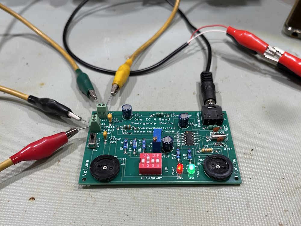
This is a neat little kit that was provided to me for review.
This is from the same vendor as the crystal radio kit, and can be purchased at the same eBay store. The kit itself is $20, which is really reasonable for a kit like this. it’s got enough parts to keep you busy for a couple of hours, and is what I would consider a “beginner with some experience” level. There’s nothing really here that should prevent someone with a soldering iron and some patience from assembling.
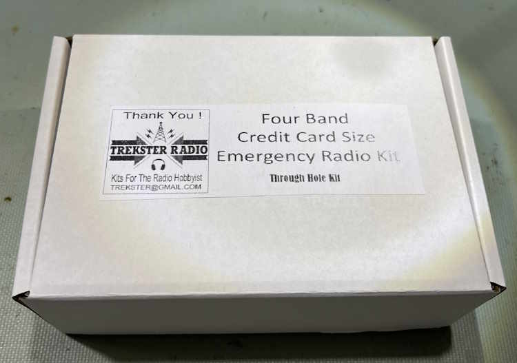
It comes packed, of course, in a neat little box:
Inside the box, we have all of the parts, including a PCB with the main IC soldered in place. You can request the IC be left unsoldered if you prefer to do it yourself, but as SMT is a bit beyond beginner the choice is yours. Advise the seller of your preference when ordering.
Some general notes on building kits
If you’re serious about building stuff like this, purchase or 3-D print a component bender. These are triangular shaped plastic tools with slots in them for various size parts, and the spacing gets bigger (obviously?) as the triangle grows. It makes for neat installation, although it’s not a necessary item. For this particular board, the spacing for resistors and inductors is 0.4”, which is usually the smallest you can bend a 1/4” part and still have enough lead that you’re not damaging the part body.
For marked parts, i.e. parts with a printed value, always try to keep the value face pointed in a direction where you can easily read it. Small capacitors like the 27pF parts in this kit are good examples. While you know what they are now, you may not remember later and having them easily visible is always good practice.
For other parts, like electrolytics and LEDs, never trust that the long lead is the anode side. While this is “common industry language,” I’ve seen parts made with equal, or even opposite leads over the years. Always verify before installation. View the markings on capacitors, measure LEDs with a diode checker if you’re unsure. That minute you spend could save a lot of time in the future.
For parts like capacitors that have a meniscus (coating) that goes down the leads, it’s best to try and raise them up a bit when soldering. This is to prevent the coating from being down in your solder. Electrolytics are similar, except you’re not trying to prevent contamination, you’re giving yourself a little room to see if the capacitor pukes out it’s electrolyte over the years. A small piece of 22ga insulated wire will work wonders here, just use it as a lift under the part as you solder and then pull it out when done.
And last, but not least - while you don’t need to clean the flux off a board, if you want to wash the board, do it before installing things like potentiometers and other parts that can get flux ingress. You don’t want your moving items to become not-moving because it’s gummed up with flux. Be careful if you’re cleaning after everything is installed as not to contaminate moving parts.
The kit itself.
Like the crystal radio kit, this went together easily. The board is well marked, and even without the instruction leaflet you should have no trouble assembling this item if you have any kind of electronics experience. Pay attention to polarities on capacitors and LEDs, of course - everything else is place and solder.
I like to put a component in, tack it quickly on the front side (resistors and inductors,) and then do any forming or cutting of leads on the backside before fully soldering. That’s the “technically proper” way of doing this, form, cut, solder. Diagonal cutters put a lot of stress on a lead, and you can crack joints. While this is unlikely, cut your leads so that you have some small amount of wire sticking up from the board and solder the part in, making sure to pick the lead that’s unsoldered first!
For parts you’re lifting, just hold gently with a finger and get a little solder on your iron tip and quickly hit the joint. Form, cut, and the solder the part in properly, and remove the lift.
It took me about 90 minutes to assemble, but I wasn’t in a hurry. You could probably do this in under an hour if you wanted, but take your time. Make sure you get good flow-through and nice shiny joints. It’s not going anywhere.
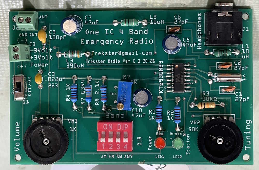
I ended up with a nicely populated board:
Testing
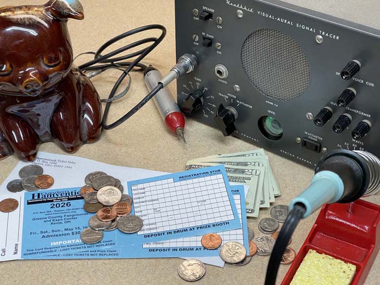
For this test, I set the radio up with some wire leads and used my bench supply to get 3VDC. The creator pipes input voltage in via a terminal, so you could use the included battery box to power the device, or you could use any source of 3V. I have an old rat shack solar array that puts out something around 3V, I’ll give it a try if we ever get a sunny day here in Ohio…this is where the emergency portion of the device shines. You can run this off of anything that has 3V somewhere. Solar, battery, probably even a bleach cell (which I want to try as soon as I get some metal and a couple of ice cube trays!)
Continuing setup, I gave it an earth ground via the local electrical system, and just tossed a cliplead over some stuff for an FM antenna. Audio was provided by my EICO 145 signal tracer, although the device really is intended for a small set of headphones.
How’s well does it work?
Very well! I was able to tune through almost all of the major stations here with only a few of the local lo-watt ones not being present. I would assume, however, that with a proper FM dipole the radio would work much better - but as it stands, it will work with just a random piece of wire which is what you want for a device that’s supposed to be for those oh-crap moments. I need to get someplace less electrically noisy to test the other bands, and will do that as soon as I have the ability.
Power draw on the unit was about 100mA constant, so AAA batteries, if new and fresh, should give you maybe 8 hours of continuous listening. Maybe a little less depending on what kind of headphones you’re driving, and the condition of your batteries.
Final thoughts
One of the really cool things about this kit is the radio IC used tunes with resistance, instead of capacitance. That saves a lot of cost and potential failure points. It’s quite the little marvel when it comes right down to it, and I’m considering what I could use that for in my own projects. It also means no bent plates or corroded capacitance if you store it for a long period.
Beyond that?
This is an extremely attractively priced kit. It’s easy to assemble, and does something useful in the end. My opinion on this is it’s a yes. You want to build a kit that does something? Get one of these. Build it and use it as a bench radio, or test it and stash it with some small tools and wire for those situations where you may not have anything else.
Happy listening! There will be one more review in this series, coming soon!
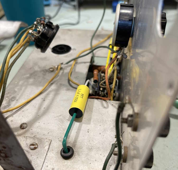
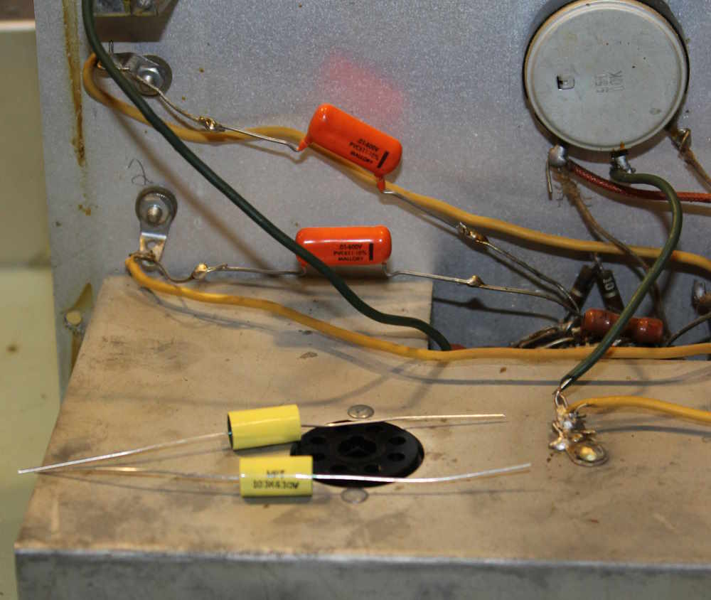
I’m going to start by replacing the two 0.1μF capacitors on the topside of the chassis. These go from terminals down to the range switch, in a j-hooked, messy sort of way. There’s some wire attached to one of the posts as well, and it’s burnt to the point where the insulation is crispy. Whomever had this before applied a lot of heat to things.
There’s not much to say about this, so here’s the before picture. The orange drops in back are probably still good, so I’ll pull them and drop them in the bin for later use. After a little cleanup, that is.
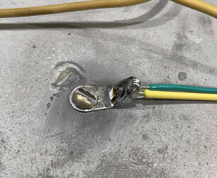
Here’s the after picture. I replaced both parts, as well as the connecting wire on the range switch, which you can just see poking up out of the chassis. It’s a yellow wire, and replaces the original that was crispy and so tightly pulled it just barely cleared the moving switch parts.
They aren’t soldered in on the terminals yet because I want to run new wire and possibly clean up that area little as well. Stay tuned, more “this sure does take a long time to replace one part” coming soon!
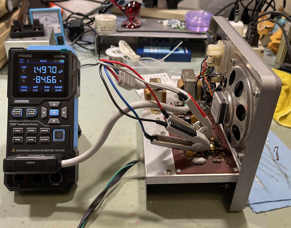
I’ve recently had to field some questions in regards to in-circuit testing of ESR. While it is true that you can’t get a 100% perfect answer while the part is in circuit, you can get a pretty good answer about the quality of the part you’re testing.
Let’s take this EICO 150 Signal Tracer. This unit works, but has very low output level. Chances are, capacitors are bad and I’ve already verified that in the observations post, which you can read at this link.
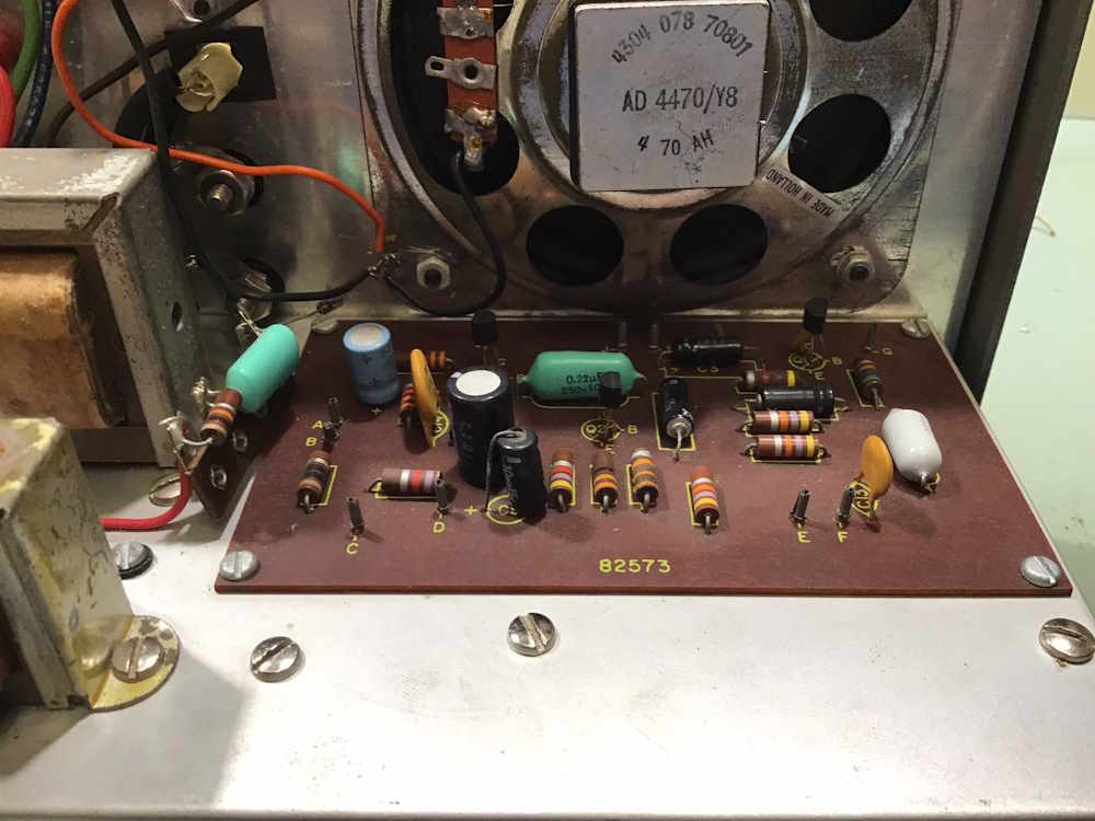
Let’s take the board of this device:
There’s a lot of little capacitors everywhere. Checking one of them with the FNIRSI LC1020E reveals a high resistance. Well, this is resistance, and not actually reactance, which is X. We’ll get to that, but this number should be a lot lower.
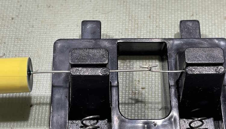
This is in-circuit. Let’s cut the lead so we’re isolating the part.
It’s still bad.
Ah ha, but that’s the resistance, you say. Well, yes - this is the Equivalent Series Resistance of the part, and it’s what the part looks like to a circuit. This part should probably present less than 10Ω to the circuit - probably less than 5Ω if it were brand new, for this vintage of part. That it’s showing 80Ω+ out of circuit means this is bad, and all of the parts in this are bad in a similar manner.
Let’s look at actual reactance. To do that, we need to know the frequency of the measurement and the supposed value of the part. Since the part’s value is in question, we can’t simply calculate it based on marked values - but if this were a perfect capacitor, i.e. 1μF, then capacitive reactance is equal to 1 / 2 * pi * f (in Hz) * C (in Farads)
Or,
Xc = 1/2*3.14159*120*.000001, which is 1326Ω.
Well…that’s not good, is it?
Here’s the reactance as measured by the meter:
-886Ω - negative ohms? Yes, reactance is signed, and in this case capacitive reactance is at an angle of -90° from 0°. But that doesn’t read what we calculated. No, that’s because this part isn’t actually 1μF, it’s 1.496μF. Let’s calculate that:
Xc = 1/2*3.14159*120*.000001496, which is 886Ω. The math checks out, and we see the basic principle of capacitive reactance for a capacitor decreases with increases in capacitance value.
What does that mean for us? Nothing, really. It’s just interesting. We’re interested in the value presented by the AC drop and current flow of the capacitor, which is what ESR is. It’s just Eac/Iac. The EICO 150 is designed to shuffle audio around, so high resistance to audio is not good.
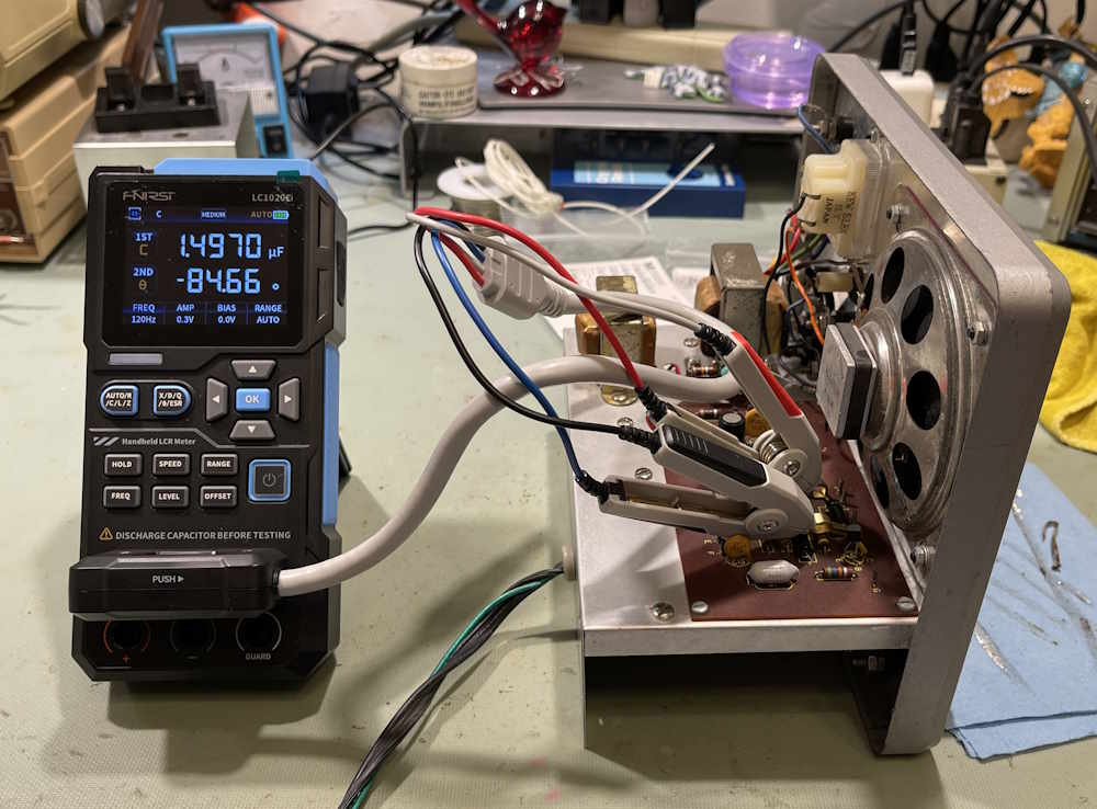
Just for giggles, here’s the phase angle of the capacitor:
-84°. A perfect capacitor doesn’t exist.
This is part of the EICO 150 repair series, but isn’t an actual part of the repair.
EICO 150 Project Hub: Coming when the project is completed.
This is a device I’ve been looking for, for quite some time. It’s somewhat rare on the market, I’m not sure if that’s because by the time this came about a signal tracer wasn’t as useful as in the past, or if people just keep them because they’re still useful and there’s no tubes to worry about. Regardless, I had to open my wallet and toss some money around to acquire it.
This was originally going to be accompanied by a video on YouTube. However, YouTube is very restrictive these days in what they allow, how you can upload it, and the amount and time of uploads. That, coupled with a camera failure wherein the camera I told to focus on my work subject actually focused on a device behind it made that impossible for now. I may still try to do some video work, but not for this device. At least - not right now. This is relevant because I made some minor repairs and did some other items on camera, all of which were hopelessly useless.
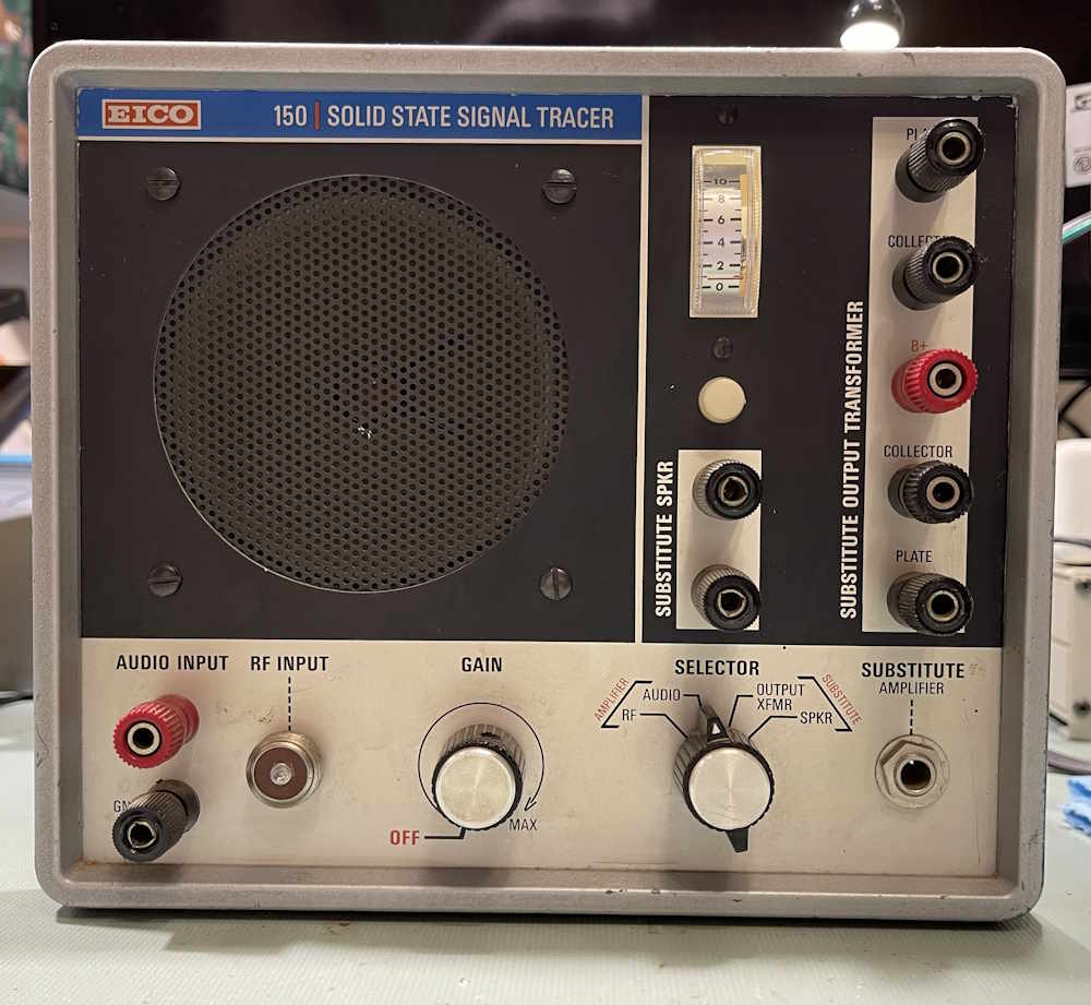
This device was probably made in 1972-3 or so, which makes it just as old as I am. It’s an audio amp, has a substitute output transformer/speaker array like other signal tracers, and uses a small meter movement instead of a magic eye. It still has that screw-on connector for RF. I’d have thought BNC would be around by now, but I guess this connector was easier to manage for the homebrew builder.
The unit is in exceptionally good shape for a used device of this age. It was used, but not abused, and I can’t really ask for much more.
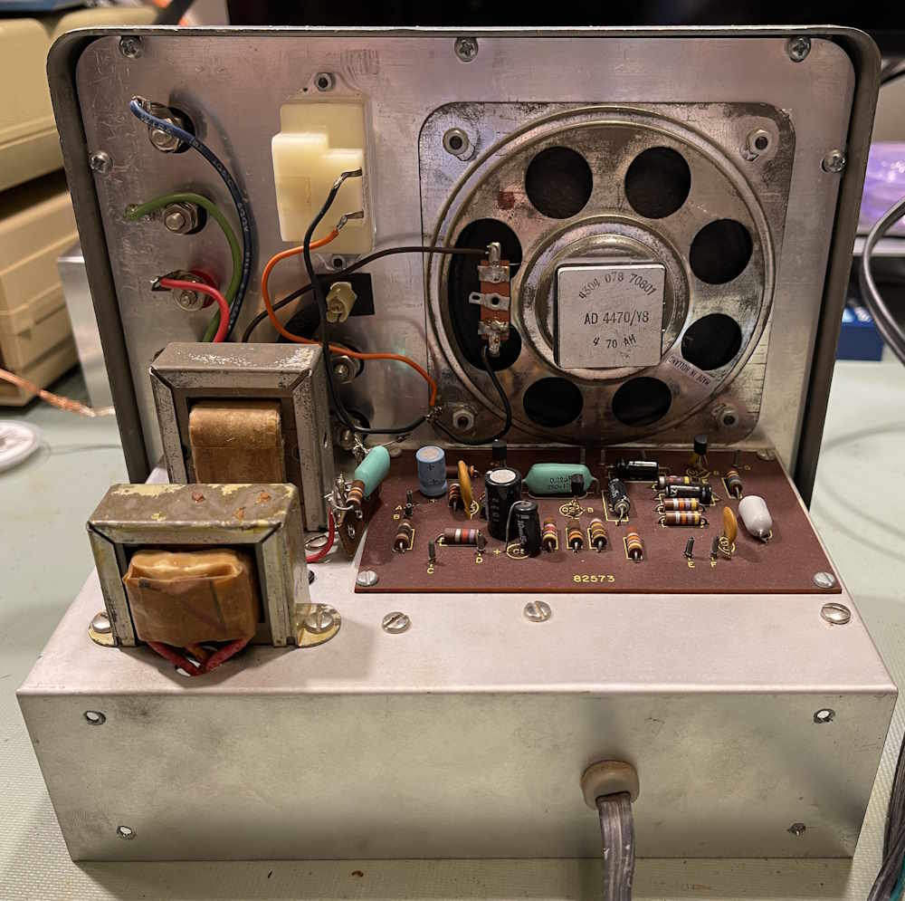
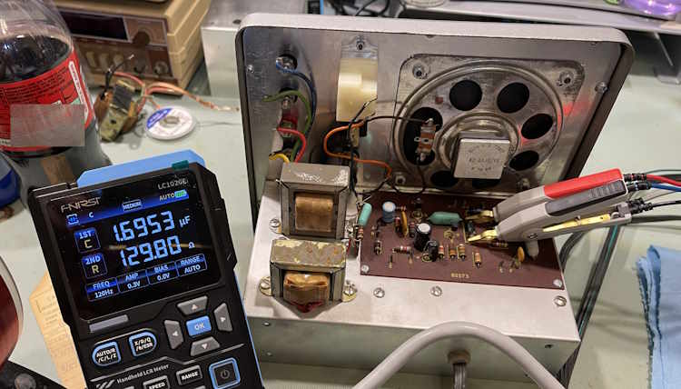
The top features the meter movement, the substitute output and circuit output transformers, speaker, and component-laden PCB.
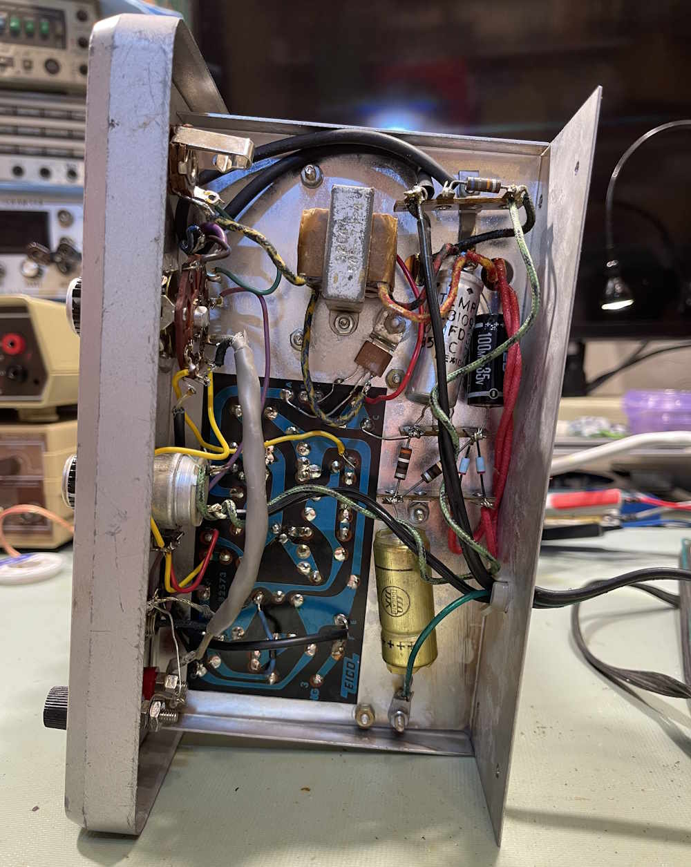
The bottom has the usual array of power items - a transformer, some capacitors, and a regulator transistor bolted directly to chassis. The bottom side is a bit messy and definitely shows some signs of having work done over the years.
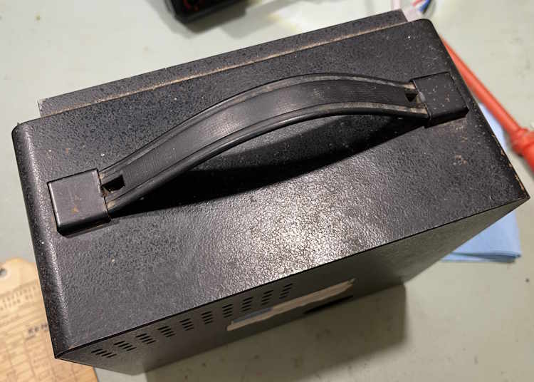
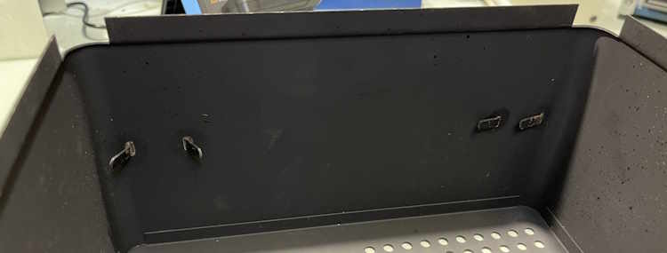
The cabinet shows some signs of use, a bit of rust and some dings. Nothing major.
The handles are just tabbed in. No more screws…I guess EICO was getting cheap.
You can see one of them has bent up slowly over the years. No biggie, it gave me the chance to remove the handle and clean it.
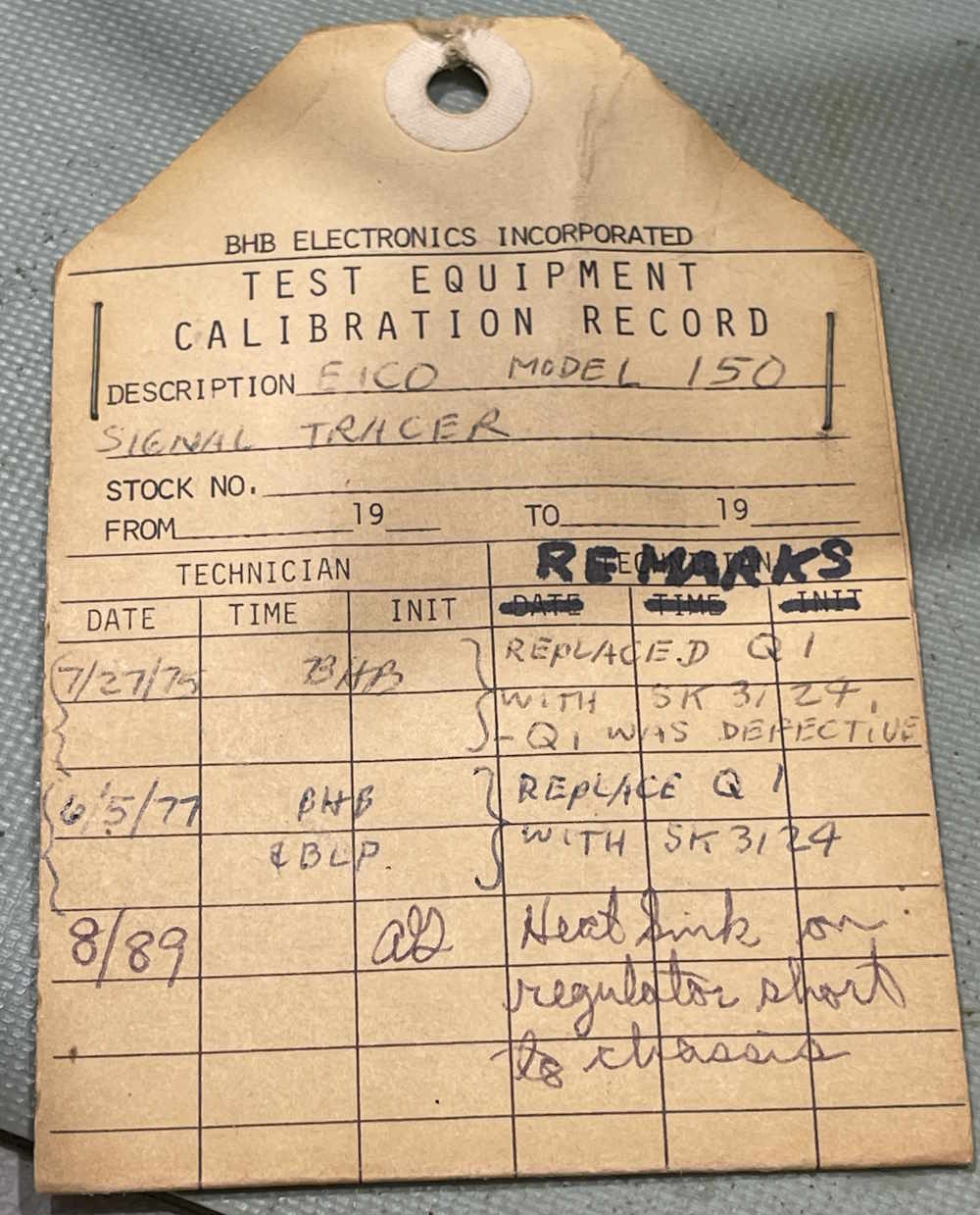
Inside the unit were a few objects, the first being this repair tag from a shop. It looks like this was on a test bench somewhere.
Kind of cool, the last time it was touched was 1989. I wonder if it was retired shortly thereafter. Note the last entry about the heat sink of the regulator shorted to chassis…
Turns out what the shop was referring to was the final output transistor. It’s an NTE152, not a regulator.
I wonder if that’s why the regulator shorted. That should be under the transistor, not floating around inside.
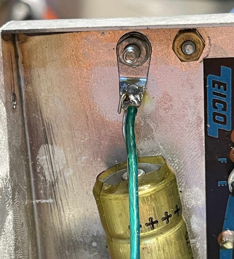
One thing I noted was a capacitor on a terminal that had no solder. It looked like it had never been soldered. Specifically, this one (that is now soldered due to the above mentioned video attempt!)
It was difficult getting this lead to take solder, but not a big deal. It’s probably going to get replaced.
I didn’t see anything that made me nervous, so I applied power and a signal. Output level is very, very low. Well…you can probably guess what that is, with all those little electrolytics on the PCB.
129Ω
All of the small capacitors onboard are well past useful, and have entered “resistor with some capacitance” territory. This device works, but needs some rework. Stay tuned (but turn up the volume!)
I’ve added some new documents to the library, and I’m going to try and create a new zip every quarter.
This archive contains all of the documents I’ve collected for projects - at least ones that I can share. This is currently about 430MB, and is an archive of zipped files of many different kinds. Grab a copy here:


