The EICO 150 Solid State Signal Tracer Part 1: Observations
Wednesday, April 22, 2026 at 07:17:05
This is a device I’ve been looking for, for quite some time. It’s somewhat rare on the market, I’m not sure if that’s because by the time this came about a signal tracer wasn’t as useful as in the past, or if people just keep them because they’re still useful and there’s no tubes to worry about. Regardless, I had to open my wallet and toss some money around to acquire it.
This was originally going to be accompanied by a video on YouTube. However, YouTube is very restrictive these days in what they allow, how you can upload it, and the amount and time of uploads. That, coupled with a camera failure wherein the camera I told to focus on my work subject actually focused on a device behind it made that impossible for now. I may still try to do some video work, but not for this device. At least - not right now. This is relevant because I made some minor repairs and did some other items on camera, all of which were hopelessly useless.
This device was probably made in 1972-3 or so, which makes it just as old as I am. It’s an audio amp, has a substitute output transformer/speaker array like other signal tracers, and uses a small meter movement instead of a magic eye. It still has that screw-on connector for RF. I’d have thought BNC would be around by now, but I guess this connector was easier to manage for the homebrew builder.
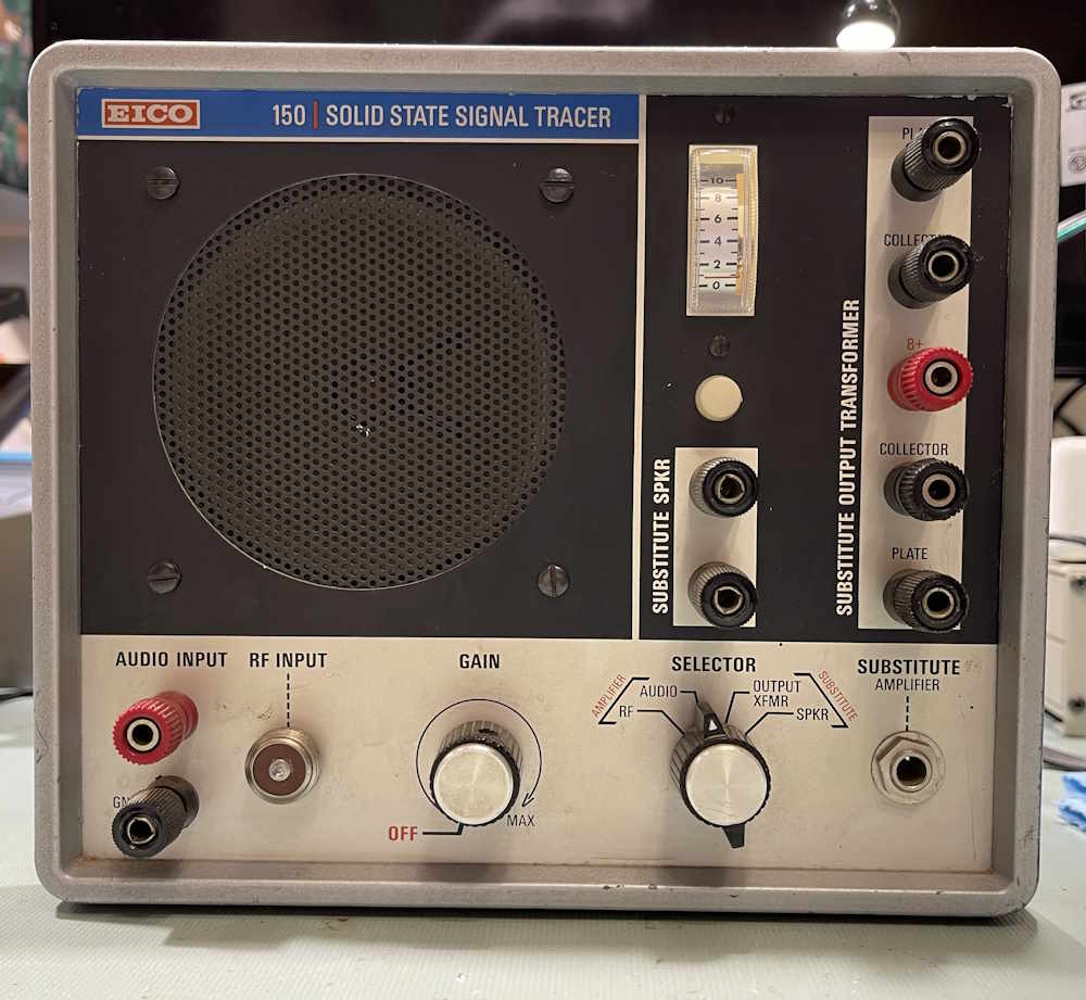
The unit is in exceptionally good shape for a used device of this age. It was used, but not abused, and I can’t really ask for much more.
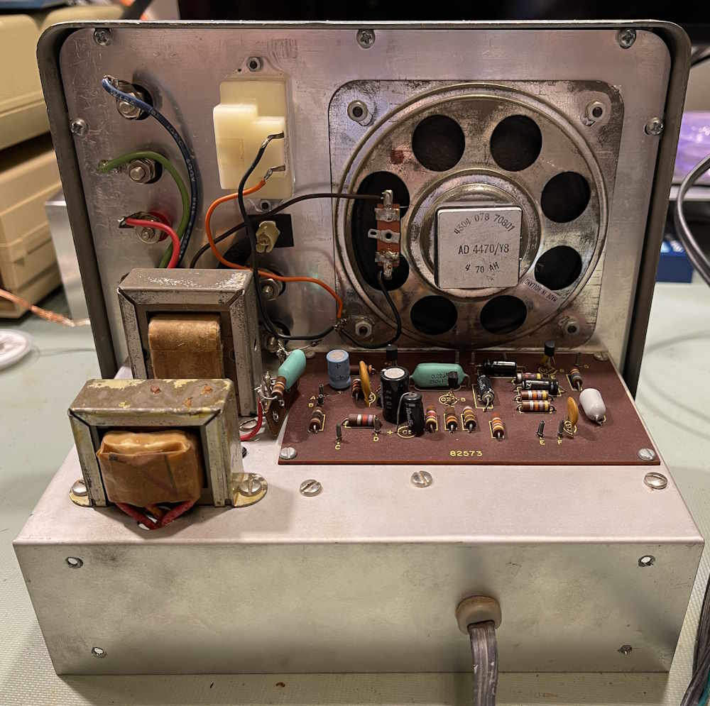
The top features the meter movement, the substitute output and circuit output transformers, speaker, and component-laden PCB.
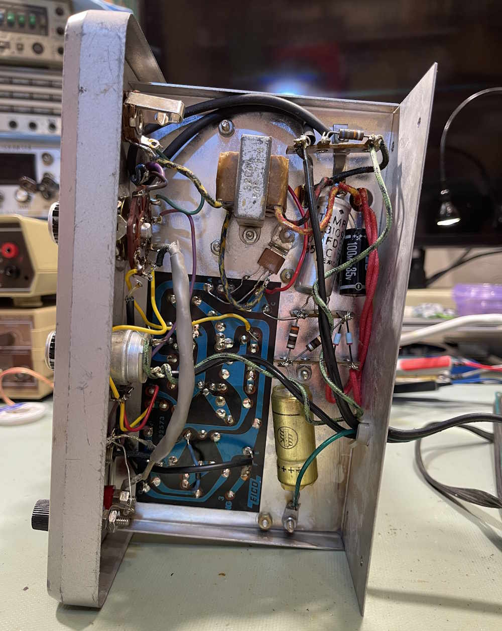
The bottom has the usual array of power items - a transformer, some capacitors, and a regulator transistor bolted directly to chassis. The bottom side is a bit messy and definitely shows some signs of having work done over the years.
The cabinet shows some signs of use, a bit of rust and some dings. Nothing major.
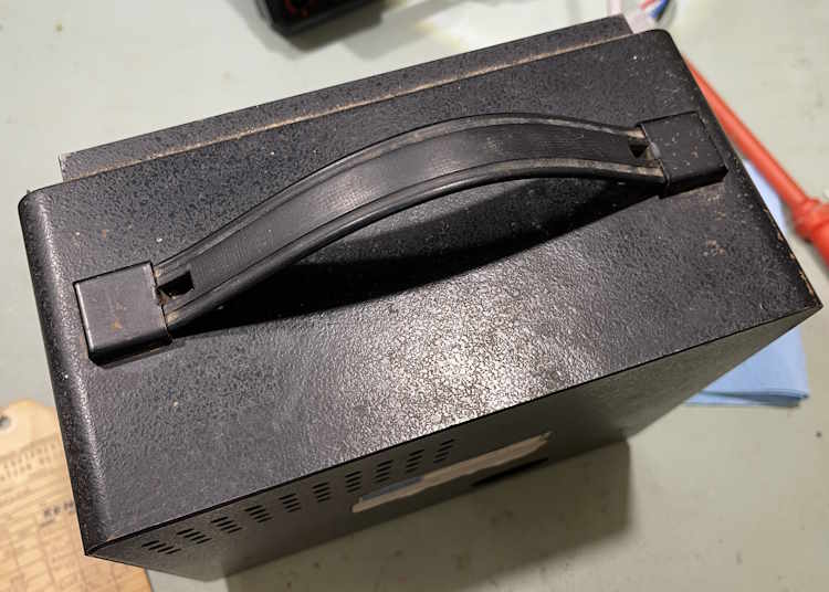
The handles are just tabbed in. No more screws…I guess EICO was getting cheap.
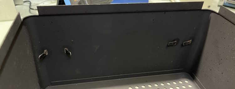
You can see one of them has bent up slowly over the years. No biggie, it gave me the chance to remove the handle and clean it.
Inside the unit were a few objects, the first being this repair tag from a shop. It looks like this was on a test bench somewhere.
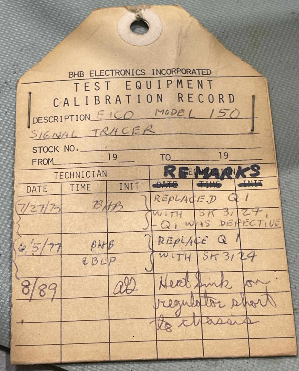
Kind of cool, the last time it was touched was 1989. I wonder if it was retired shortly thereafter. Note the last entry about the heat sink of the regulator shorted to chassis…
Turns out what the shop was referring to was the final output transistor. It’s an NTE152, not a regulator.

I wonder if that’s why the regulator shorted. That should be under the transistor, not floating around inside.
One thing I noted was a capacitor on a terminal that had no solder. It looked like it had never been soldered. Specifically, this one (that is now soldered due to the above mentioned video attempt!)
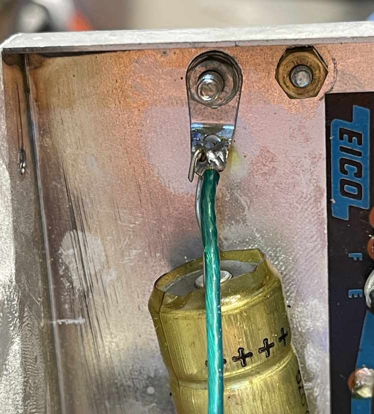
It was difficult getting this lead to take solder, but not a big deal. It’s probably going to get replaced.
I didn’t see anything that made me nervous, so I applied power and a signal. Output level is very, very low. Well…you can probably guess what that is, with all those little electrolytics on the PCB.
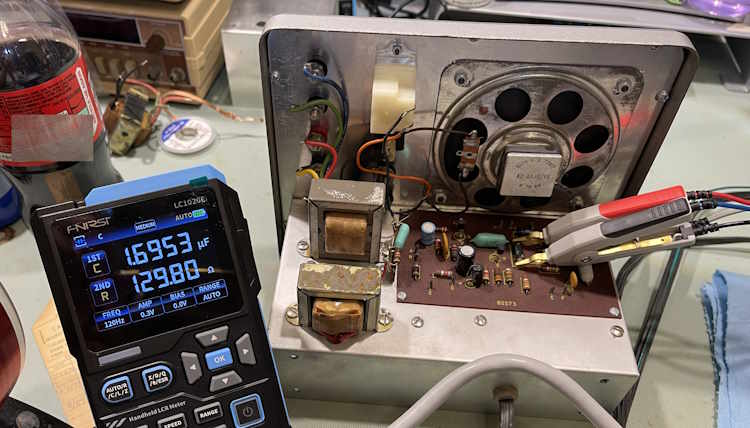
129Ω
All of the small capacitors onboard are well past useful, and have entered “resistor with some capacitance” territory. This device works, but needs some rework. Stay tuned (but turn up the volume!)
Next part of this series: https://wereboar.com … pacitors-everywhere/
Wrapup and final thoughts: https://wereboar.com … -and-final-thoughts/
References
The EICO 150 Signal Tracer Ops / Parts / Schematics manual: https://wereboar.com … 0and%20Parts.pdf.zip