The EICO 150 Solid State Signal Tracer Part 3: It’s wired wrong.
Thursday, April 30, 2026 at 06:37:10
I’ve been slowly going through this device, checking parts because the output seems very low and distorted. I can overdrive one of the interstage transistors with not much input, there’s something wrong.
Here’s what I’ve come up with:
1. Leaking coupling capacitor. Unlikely, in my opinion, because the voltages here are pretty low.
2. A resistor or other part has simply gone bad. Possible, but I checked resistors and while some are out of tolerance, none are what I would consider terrible for a carbon composition resistor.
3. There’s a wiring error present.
Let’s focus on #3. After going through the unit, verifying what I could, I started checking bias on transistors. The bias on the final output should be 0V at the collector.
Here’s a schematic of that final output, Q4, and the output transformer that couples it to the speaker:
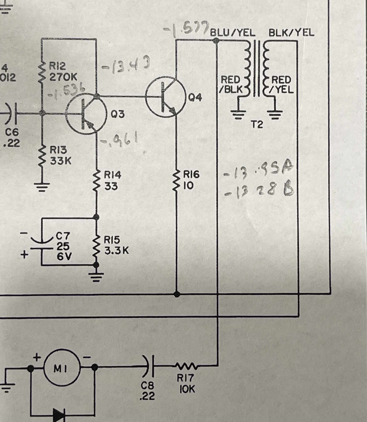
I have -1.577 noted on the collector. That’s not right, it should be 0, or very close to it as there’s no DC resistance on the input side of the transformer.
Now…note that there are two sections. One is identified by a Red/Black to ground, the other, Red/Yellow to ground. The input sides are also differently colored, but they don’t really call attention to that in person. We’ll get to that later.
You can probably guess what happened, and there was something in the back of my head going “The output isn’t right, but I don’t know why. Check that closely.”
The original builder connected the 16Ω speaker output side to the transistor. Not only was it trying to drive a 0.7Ω load into a 16Ω speaker, the output transistor was trying to drive into the wrong impedance. I’m really surprised it even worked, and it may explain why the output was driving excessive voltage into the transformer. Fortunately, the transformer seems to be good…I hope. There is about 15MΩ of leakage across the windings, but that could just be normal for this guy.
While I haven’t changed the order of the wiring yet (probably going to require some wire stretching,) I imagine this will probably help the output levels substantially.
Why did they do this? Well…
1: They didn’t bother measuring and didn’t pay attention to the colors on the Yellow/XXX (and to be fair it’s very difficult to differentiate in person, the camera reveals more color than the naked eye does,)
2: They wanted to use the higher impedance input side as an output for high impedance headphones.
I’d guess #1. Well, yes…but no.
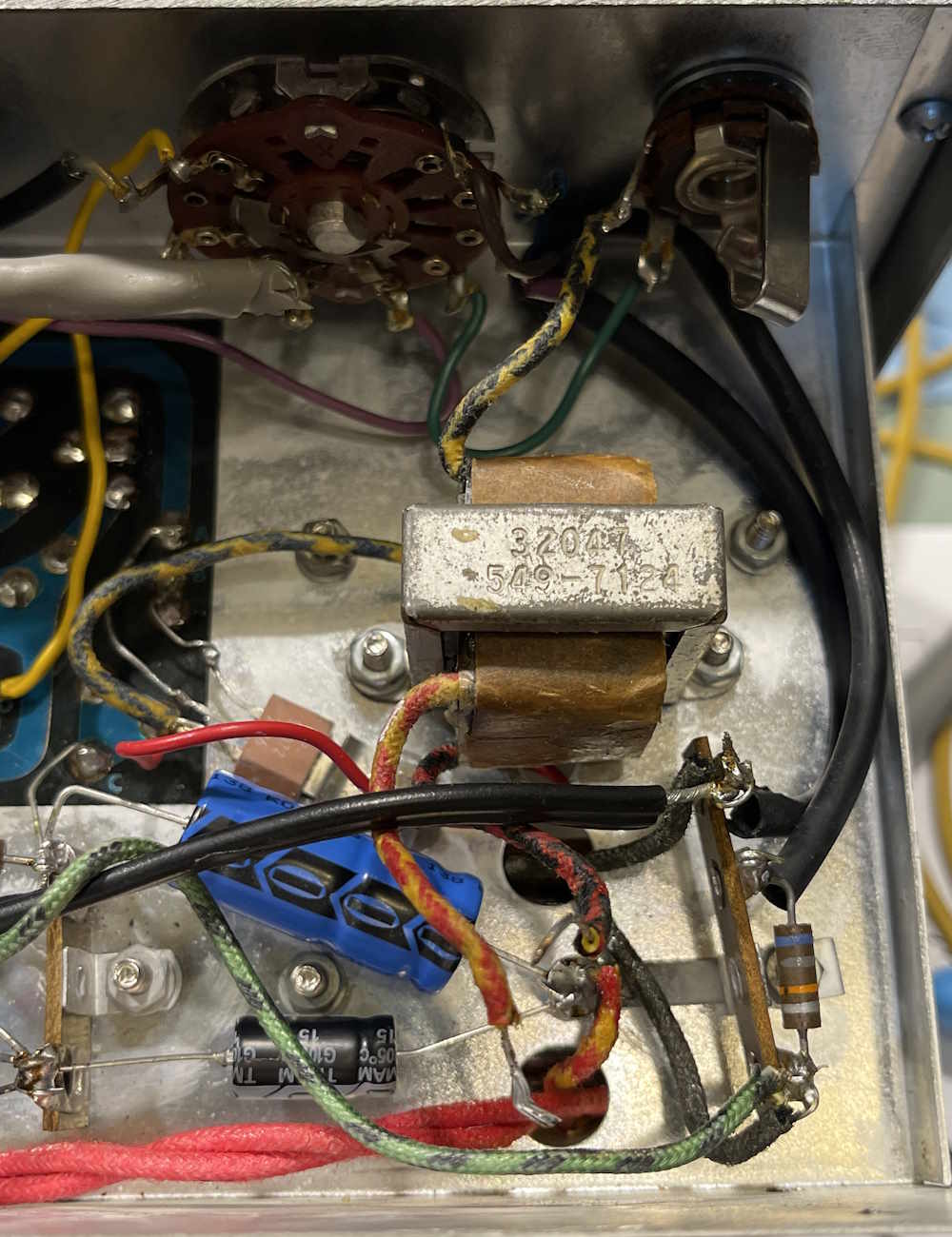
I measured the connections with a meter. Yellow/Black and Red/Black are connected! The transformer was made wrong. The person that wired it wired it properly based on the colors. It worked (poorly) so they just assumed it is what it is and moved on! I wonder if that had anything to do with the problematic transistor repairs early in it’s life?
Maybe not?
The transformer, while wired wrong, was probably installed correctly. It’s been so long since I’ve worked with this kind of device that I don’t have any reference these days. The primary should be low ohms, and the secondary should be quite low.
When I measure the 8 ohm speaker, it’s shorted. That’s probably the issue. I just need to get hold of an 8 ohm speaker, and rat shack isn’t there for me anymore…
I made the changes to the circuit and it’s worse. But the speaker is certainly a problem. More troubleshooting to come.
Stay tuned!
Next part of this series: https://wereboar.com … t-4-its-the-speaker/
Previous part of this series: https://wereboar.com … pacitors-everywhere/
Wrapup and final thoughts: https://wereboar.com … -and-final-thoughts/