This probably should have been inserted before the Findlay show, as it happened over Labor Day weekend. But I’m a lazy piggy and didn’t get it posted in time, so here it is!
Swappers Day is a general flea market that happens over the Labor Day weekend. By general, I mean it’s all kinds of merchandise - but it started out as a sportsman’s club show, and you still get a lot of firearms and bows being sold. Kind of a strange mix of things.
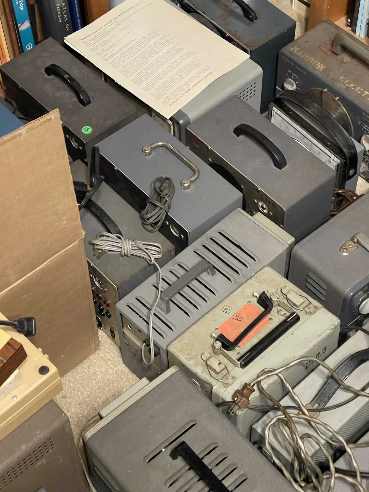
A lot of general antiques also show up, and that includes electrical gear. However, this is an opportunity to take photos of all kinds of interesting things, and here’s what I saw that caught my eye:
This stuff is getting kind of rare, but cool to see.
As is this stuff…no prices of course. Price it!
I think Coyote was just a masochist, and the roadrunner was his enabler.
A cute mini motobike.
It's like a bike. But for water.
A relative that messed around with the wrong crowd.
Interesting, but relatively poor shape.
I took the Stewart unit home.
We had no idea what this was, just…trippy.
But they were everywhere this year.
Yeah we all had one of these.
.
Not much else to say about this one, but more shows on the way!
The Findlay Radio Club Hamfest is usually a pretty decent show. It’s been shrinking somewhat over the years, which is unfortunate, but there seems to be a lot of ‘fests in Ohio these days. Perhaps that, and the general aging of the population / equipment getting older and not having more made is starting to affect who and what shows up. No idea, but this years show was probably about 2/3 of the size of the first one I attended years ago. I may put this one on every other year or so…
That’s not to say there wasn’t good stuff to see, I usually bring home way too many things from this show and this year was no exception. There was plenty of good stuff to see, and it was still well worth the trip.
I did notice that prices seem to have come back down again, after the exuberance of the first half of the year. They’ve come down a lot, to the point where I noticed a certain piece of equipment that would make a good economic indicator. More on that later!
Regardless, it was a lovely day for the show and I took a number of pictures of interesting things:
A (Sears) Silvertone Battery Checker.
Chinese bootleg Blu-Ray discs from years past.
The big rigs still show up in great numbers.
I almost took the AG-9 home, but it was damaged.
A big 'ol boat anchor Majestic.
A relatively rare clock model.
The hotdesk scanner! Hot!
Just off the boat from Japan.
This was only a buck. These were built like tanks.
It's so cute.
A couple of interesting radios.
Multiply your Qs here.
It's too bad this meter was smashed.
An early personal radio.
A bunch of interesting broadcast receivers.
The S-38s are cheap again.
I took this wattmeter home.
It's a mini phone!
A collection of old phones.
Tube testers.
If you say that wrong you get in trouble.
A 150VAC Weston meter. I took it home.
That's a cool Zenith radio.
.
There are a couple more shows this year before the season wraps up, including a new one in Pennsylvania that I’m going to check out. Stay tuned, and I’ll see you there!
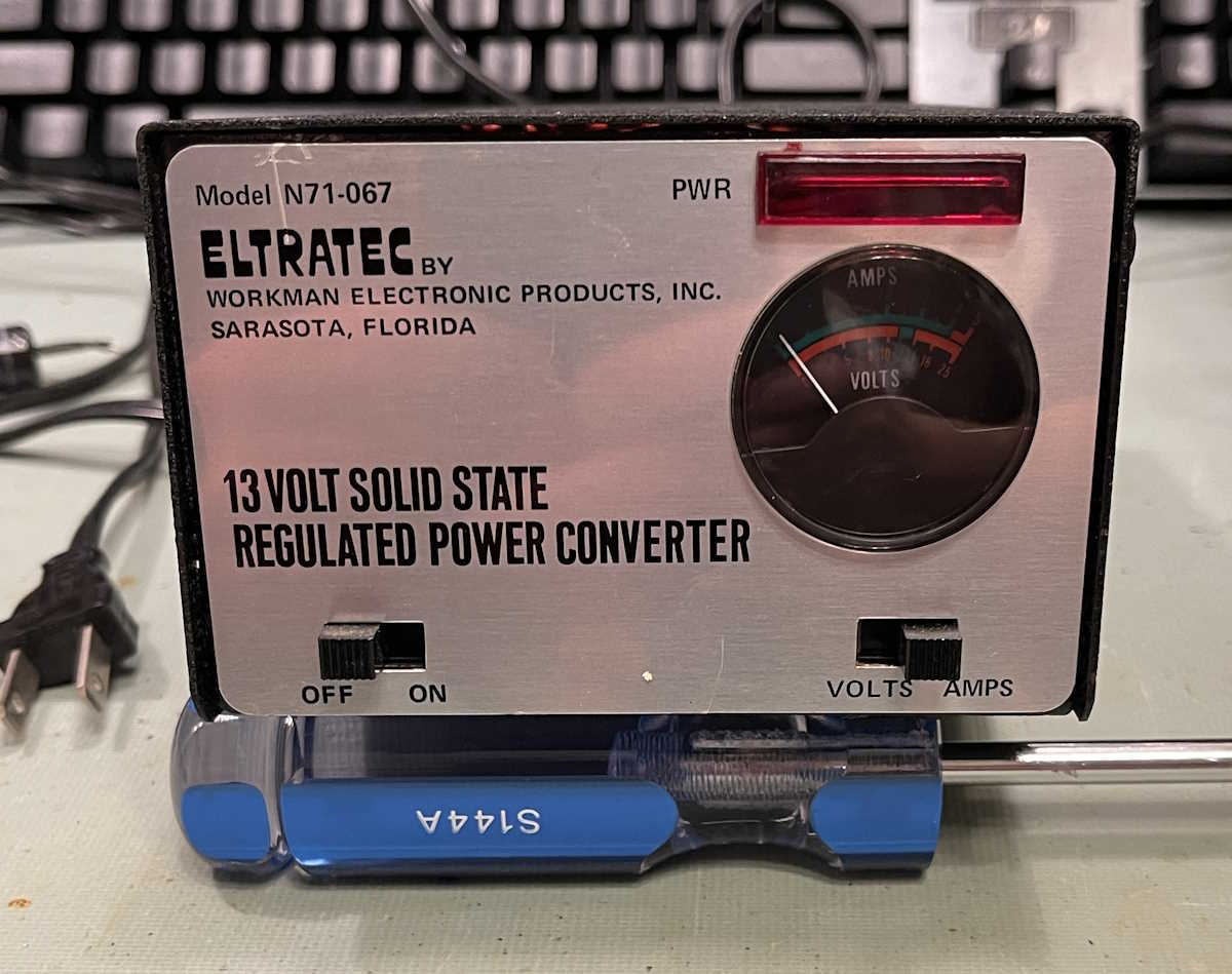
I picked this up at the Columbus Hamfest, mostly for the 1970s vibe it has. I love that round meter.
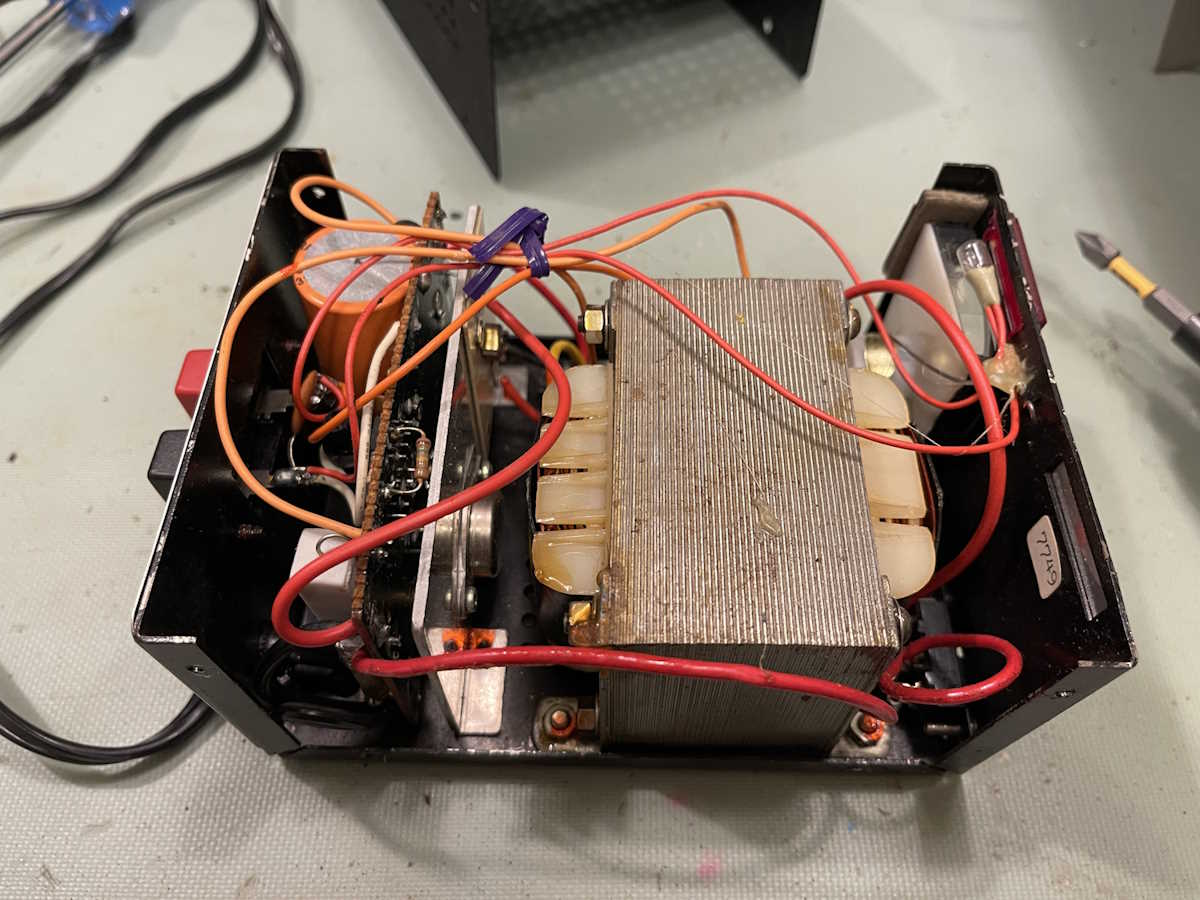
The inside is what you’d expect from this kind of device.
It looks to be a standard (reference) LM723 circuit with a series bypass transistor to step the current up. That’s also expected, it’s not like there was much else at the time. Note the 1977 date code sticker and the bread tie for the wires!
I can’t find a lot on this company. There’s one of the same name, but they are (were?) in Delta, Ohio - not Florida. Regardless, their website is broken and has a last date of 2004. There are a few other references here and there, but nothing concrete. I have to assume that this variant went away after the CB era ended.
Does it work?
No.
It’s supposed to be 13.8VDC, not 26. That’s probably the max that the device can put out, and the pilot lamp is just screaming here.
So what’s wrong?
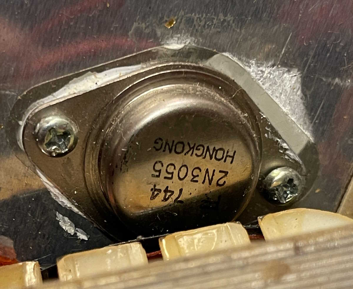
The big transistor is my first check. It’s somewhat shorted B-E, but it has a resistor across those leads. The only way to actually check it is to pull it out - which will need to happen if the board is accessed, seeing as how the heatsink covers traces. The transistor checks fine once out of the circuit.
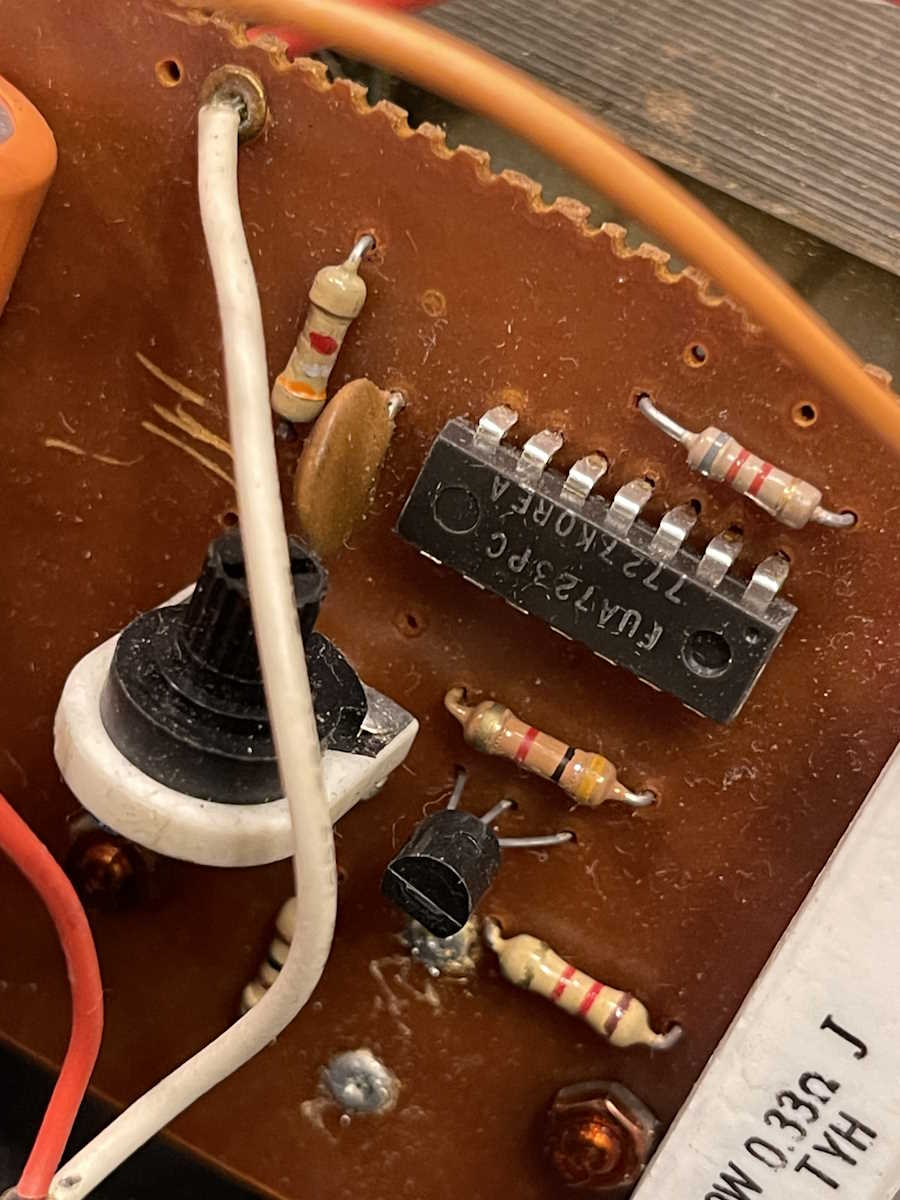
There’s a small buffer transistor as a driver for the series pass transistor. This one doesn’t seem good. But this one is right across the LM723, so there’s no way to tell which one is bad without pulling one out. The transistor is easiest, so we’ll do that. But, if the transistor is bad, the LM723 might be bad as well. I’m just going to order both parts and replace them both if one or the other is bad. I’m not as worried about the 2N3055 because those could handle a lot of abuse.
It’s actually surprisingly difficult to find DIP parts these days, so I turned to an old friend - Jameco. They still stock this kind of stuff, and if you order from someone else they’ll probably ship from Jameco. Check them out here:
So, this item literally followed me home from the Cincinnati Hamfest.
Seriously.
I was talking to a guy about a Simpson 260, and he asked if I was interested in a radio. I said no, I had an old coffin TRF in the queue. He picked this up and handed it to me and said “If you do something with it, you can have it.” I said “I promise it will go on the bench, but nothing more than that.” Deal done.
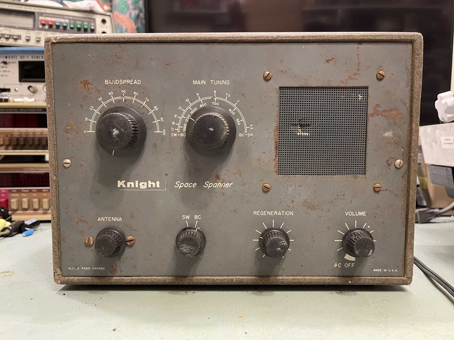
So what is this thing?
It’s a radio from Knight (Allied) called the Space Spanner. It covers broadcast and shortwave bands. It’s based on an old design called a regenerative receiver - essentially, the RF is re-amplified before being detected, so hopefully you get a stronger output with less active components. It’s cost-reduced before cost-reduced was a thing, and was obsolete by the time this kit was made. It was cheap, however, and allowed a new kit builder to get something and cut his teeth on it for not a lot of cash.
It’s in fairly poor condition, and probably sat in a garage after the builder moved on. Everything is there, however, so that’s a plus. The cabinet is a plastic-wrapped wooden case made from plywood, and is actually a fairly nice cabinet. It’s very dirty, however - scrubbing with 409 barely made anything except blackened towels from the dirt. (I’ve read the cabinets for these were made by a luggage company.)
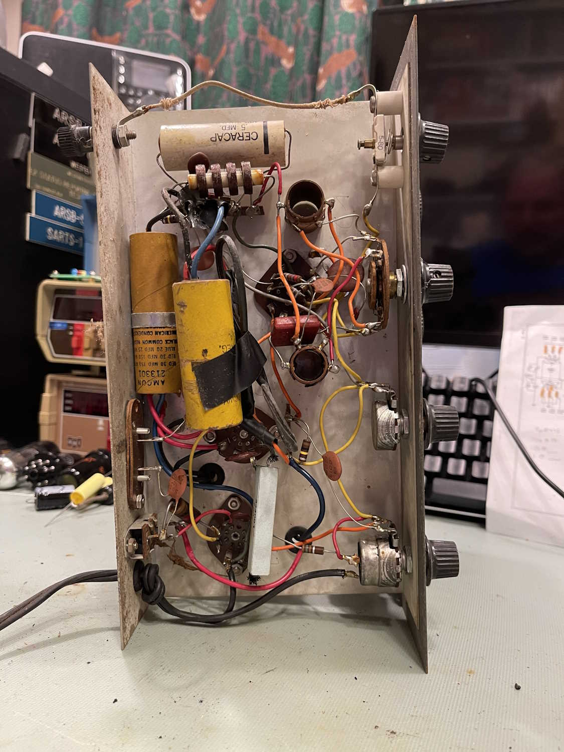
Inside, the chassis shows signs of being modified over the years. There’s a giant capacitor stuck in there, and it’s attached to the final point on the original filters. I have to assume the original is bad, and the person just stuck a 100μF in there because that’s what they had, and it worked. I’ll know more on that, later.
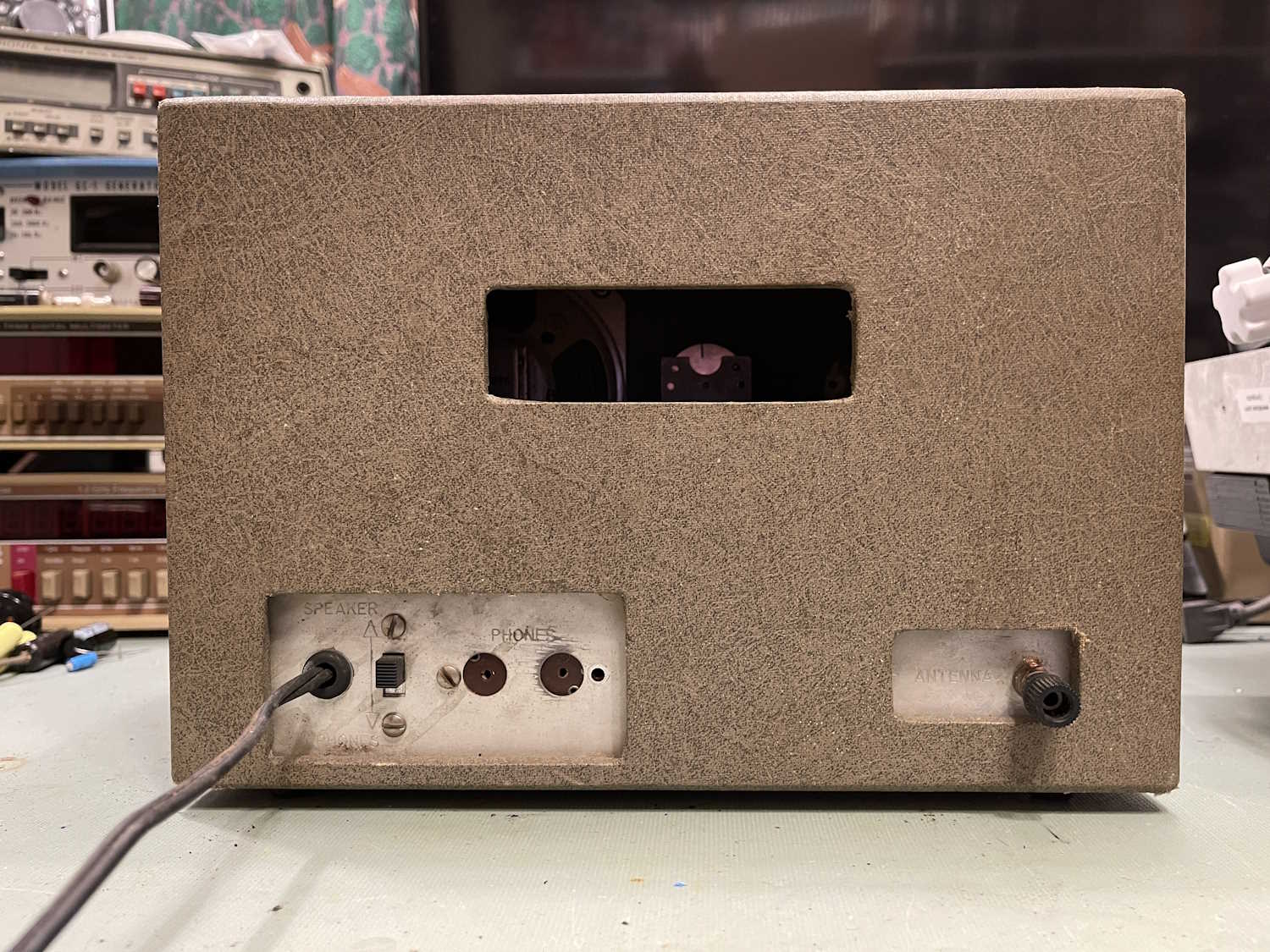
The antenna terminal is loose and the plastic portion is locked open. That’s no big deal, and a pair of needlenose fixed both the loose screw and the locked connection. Tubes are all there, and most capacitors are disc. I don’t see any real reason for concern here, so into the isolation transformer it goes. Probably should dim-bulb this, but eh…I like living life on the hot edge.
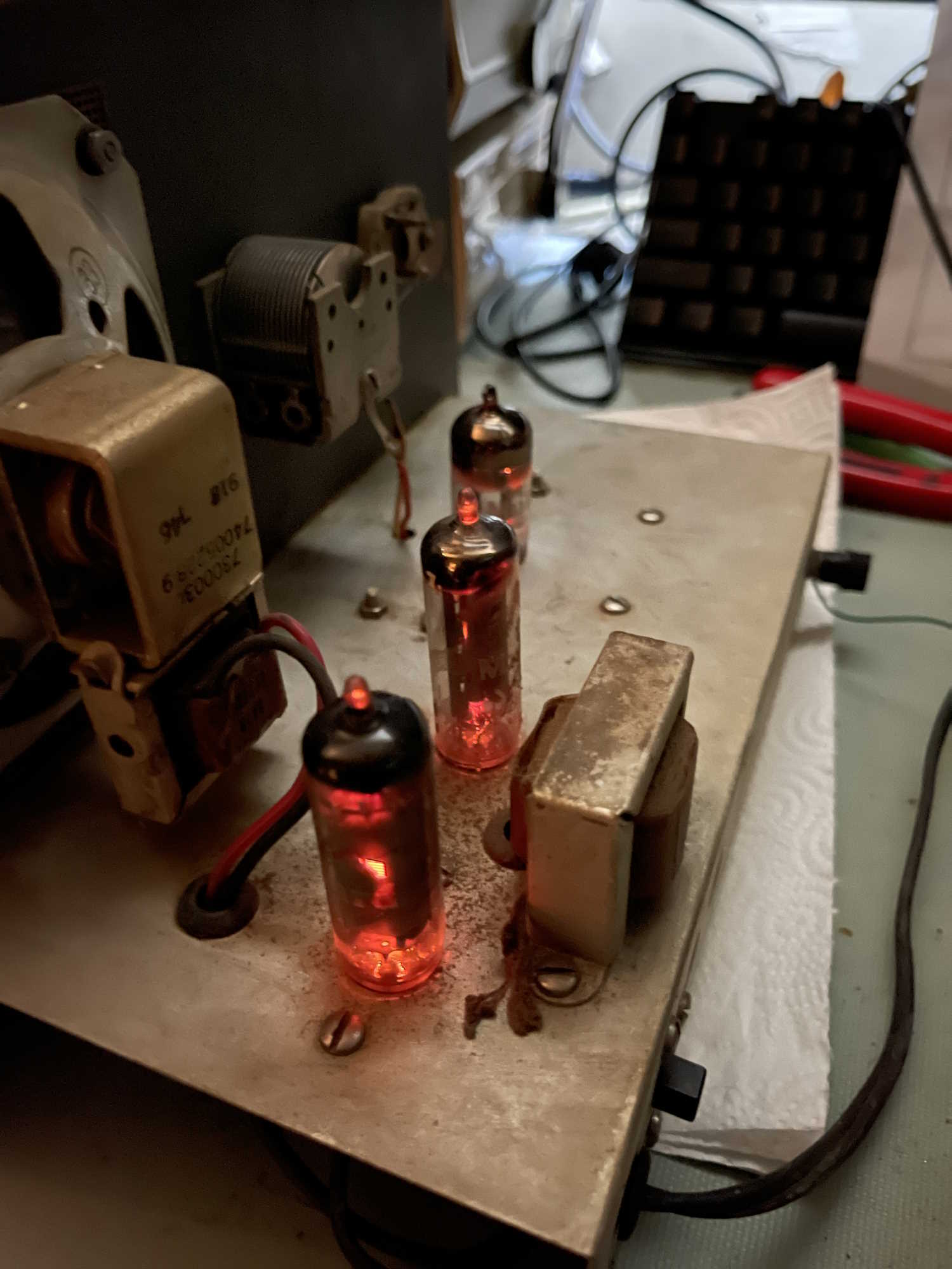
I got a little noise out of it, but nothing else. A tube wiggle made lots of noise, so I turned it off and gave all the pots and tube sockets a few drops of DeoxIT. After a good cleaning, I put the tubes back in…
It came right to life. After messing with the controls, I was able to get most of the strong local AM stations with a short piece of wire. So, the device is working, which is pretty cool.
So, what next?
I think I’m going to do a basic restore on this - new resistors and a new filter. There’s not much else, all the other parts are disc capacitors save the ceramic cap at the top, and it looks good. I do need to figure out what’s up with the antenna control, it seems like those spacers are too long and the knob won’t go on properly. I know it’s the correct knob because it both matches what is on the rest of the unit, and other images show this knob. Maybe some shorter spacers are in order, who knows.
Anyway, this is a really cool piece of old tech, and deserves a chance to live properly. Stay tuned, more on this unit coming later, rather than sooner!
For the most part, I’ve only brought home parts (or parts units) this year - prices on equipment has really gone up and it’s moving things into the “I’d like that, but not at that price” territory, with some of the stuff being so far out of budget that there’s no way you could negotiate it down.
It shouldn’t be said that there aren’t bargains around, because there are. I did pick up some interesting things because I they were unusual or cheap.
First is this device. You’ve seen it before, since I had a post on it earlier. It’s a “tube tester” - aka “filament checker” for tubes. It’s some little device a company packed up with a RCA tube manual - in this case, the manual doesn’t look like it’s ever been cracked open. That’s the primary reason I purchased this, but the gadget was cool as well. It looks to have been used maybe one or two times - probably right up until the original owner realized you could just check the filaments with a meter instead!
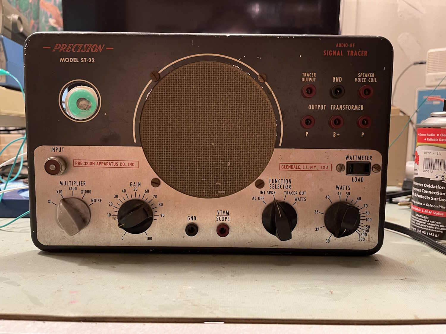
Next up is a signal tracer! Yay! Well, not really. There’s nothing special about a signal tracer save this one is one of Precision’s devices (aka PACO) and is somewhat unusual. You see more of PACO’s signal generators and other devices - I believe this ST-22 is the first tracer from that manufacturer I’ve seen. It’s in very dirty shape and missing a knob, but it works. I did some cleanup on it and borrowed a knob from a PACO G-30, and it will probably be able to get put into service with a filter change. Stay tuned for a post on that in the future.
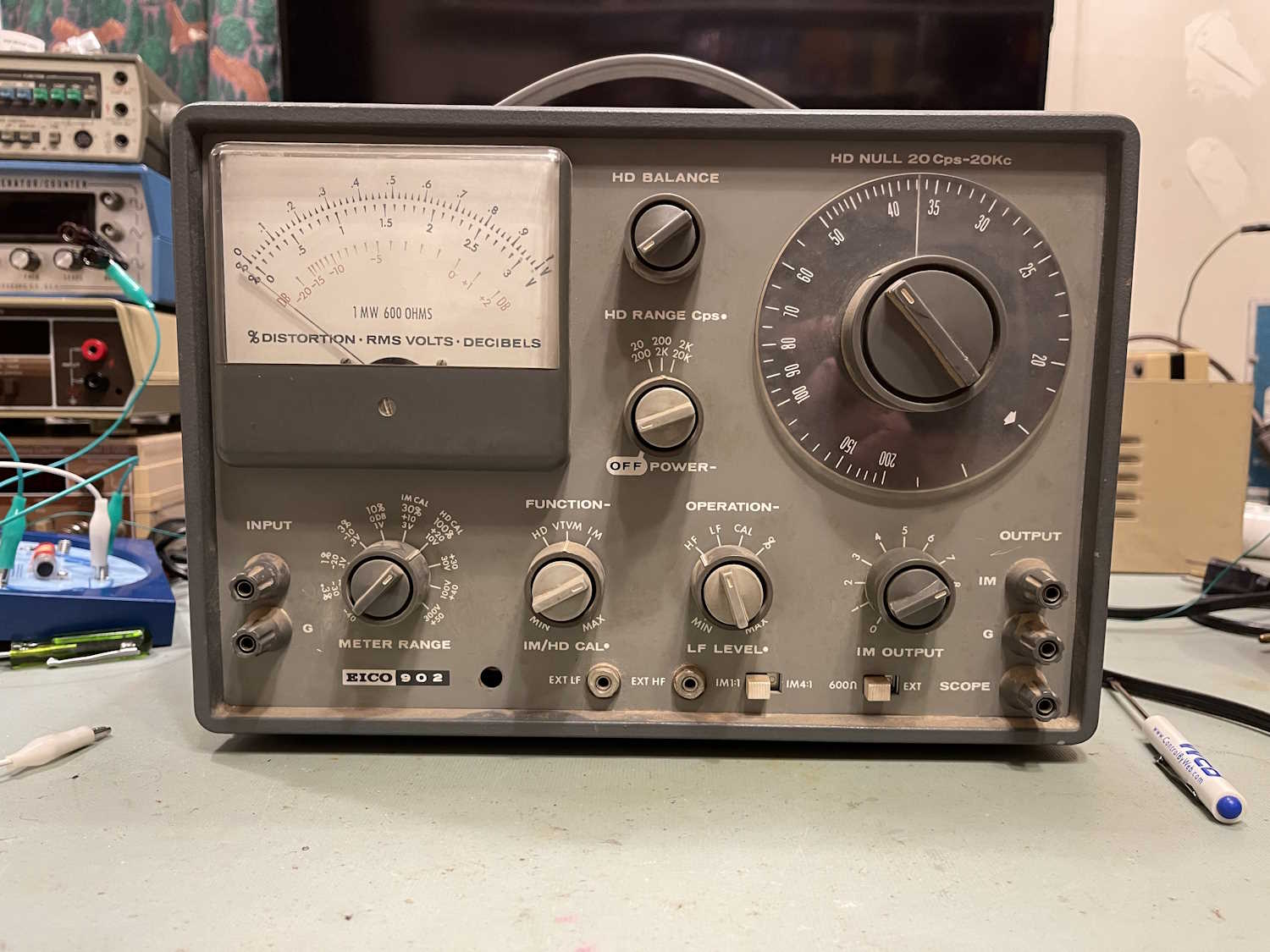
An Eico 902 Harmonic Distortion Analyzer is next up - this is a fairly late item for Eico, and as such, has very little wax paper capacitors to go bad. That’s good, because this is a fairly complex device under the hood. Providing some of the same measurements as the AA-1 and IM-48, this device could do both AC VTVM measurements as well as provide harmonic distortion measurements for audio amplifiers. While I don’t do a whole lot of audio work, this device was so cheap I really couldn’t pass it up. Next year, this will probably be back to 3 figures, so I picked it up now. There will be some posts on this one later as well.
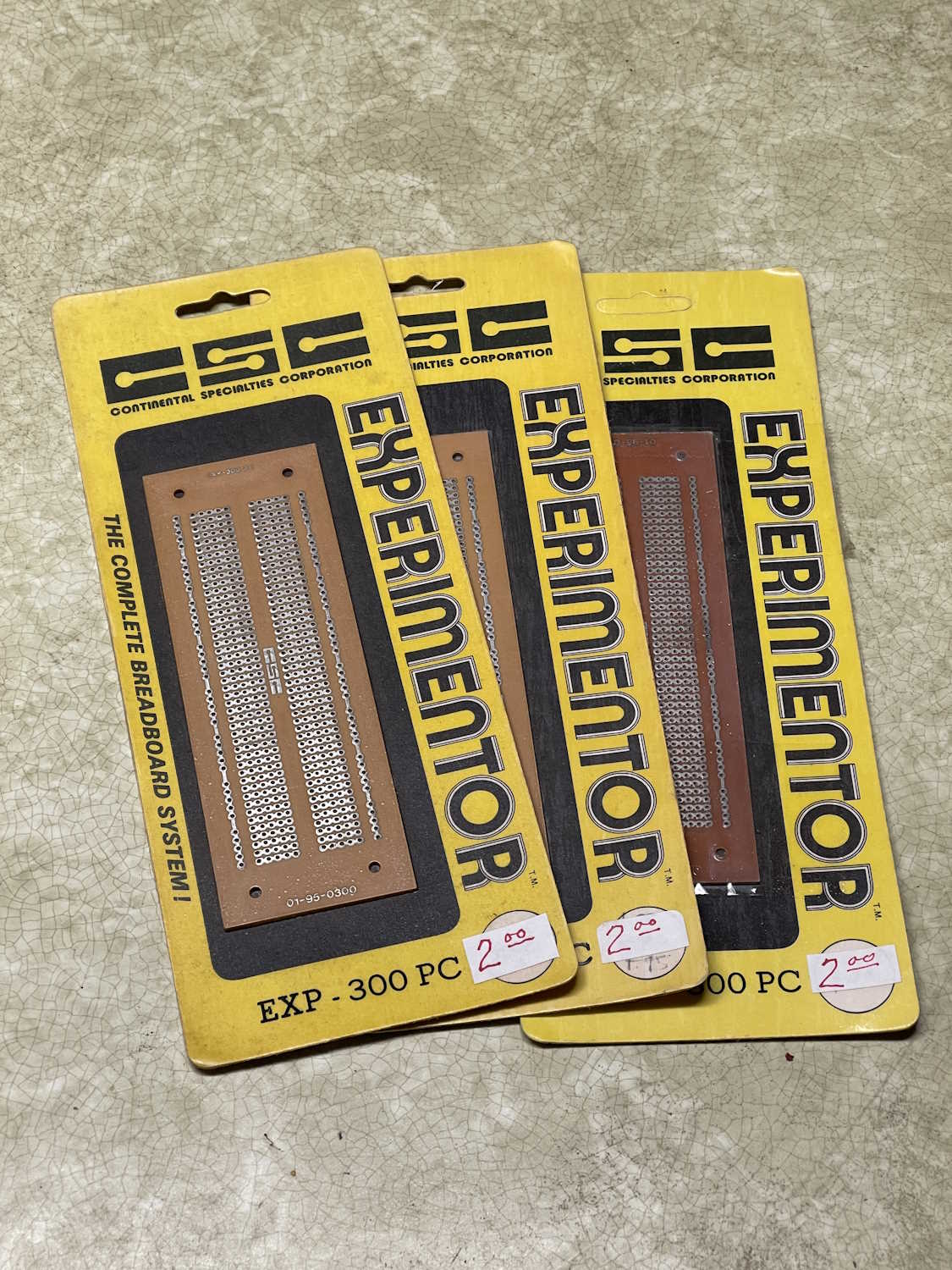
Last, are some rather banal parts. These CSC (Continental Specialties Corporation) proto-boards match standard breadboard layout. You’ll probably recognize these - everyone from Radio Shack to no-name Chinese vendors sold a board with this exact same layout. Since I use these at times, and you can’t get them from the rats at the shack anymore, I picked these up for a few bucks. The 1970s packaging is just a bonus.
That takes care of finds from the first part of the year. Next show(s) are Columbus and Cincinnati in August, with a few more in September and November. Stay tuned for pictures of the goodies that show up!
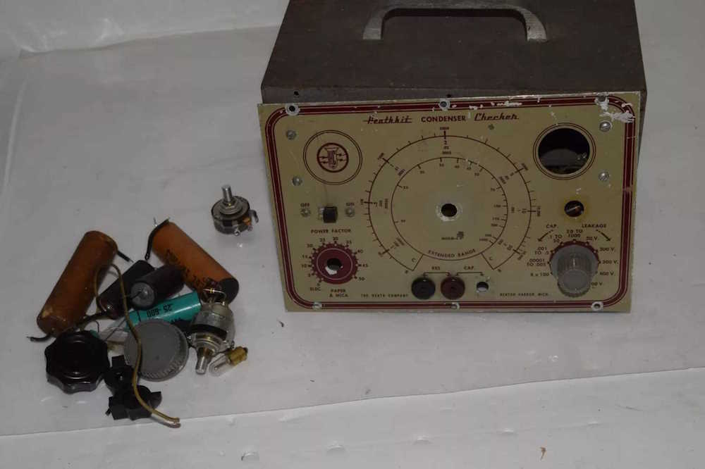
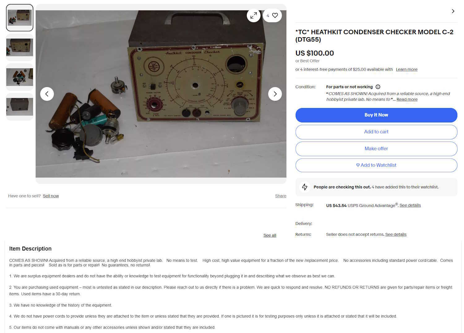
Here’s a Heathkit C-2 “Condenser Analyzer” for sale. It’s listed at $100 with almost $44 in shipping.
For some reason, capacitor analyzers of this nature have become the hot thing. It’s in part due to the glowing green magic eye tube that these used as their primary output display indicator, but also (I’ve been told) people use these and their high-voltage outputs to “reform” old capacitors for reuse. Why? I guess because the Internet told them that old=good, new=garbage.
You’ll notice this thing is in fairly poor condition. It has a pile of parts included with it. Some of them obviously came from the device. Some did not. All of them had to be cut out of circuit in order to be in this pile. It looks like someone just grabbed a handful of things nearby and added them to the image.
These devices were a very simplistic variant of the capacitor checker, and had a small chassis at the top that contained the power and eye tube circuitry. It appears to still be there by the screws in the panel, but that’s about it. The eye tube is missing. Two of the three controls are missing (are they in the pile?) The leakage lamp is gone, and the panel is, overall, in poor condition. We can’t see the chassis itself anywhere so there’s no guarantees that anything other than the metal is still there. Even that is suspect!
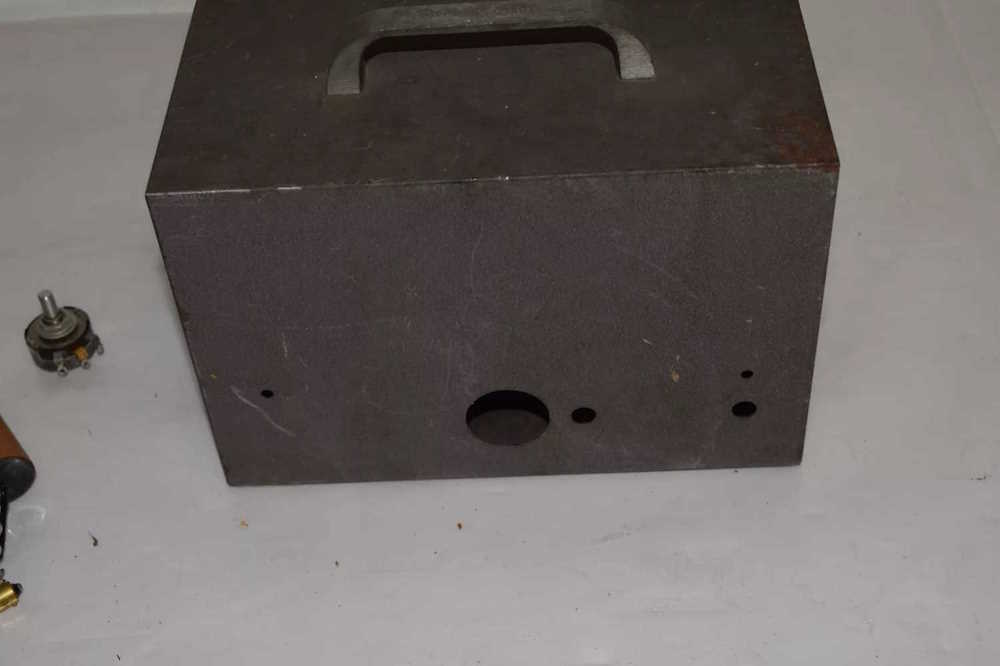
The front panel is in poor condition, but the case is in just as bad of condition. It’s intact, but rusty. The handle is still there, which is good, but that’s about it. No power cord is present, so it’s probably been cut off for some reason.
If I were to see this at a hamfest, it would probably be in the dollar box, or even the “free” box. I’d take it for a buck to get the aluminum handle and knob and dump the rest in the trash on the way out. This, in my opinion, is certainly not $144.00 worth of anything.
The good part is the description:
There’s our images again. You can plainly see they aren’t showing a chassis here, even though all of the screws are missing and it would be easy to do so. Why not? Why show the pile of parts close up but not the chassis?
But as stated, the description is pure gold.
“Acquired from a reliable source.” What’s that supposed to mean?
A “High end hobbyist private lab.” If this is the case, then this was in their junk bin.
“No knowledge of the history.” I thought this was from a reliable source, surely they could tell you something about it - especially if it was from a “lab.”
“No means to test.” No kidding. Really? The exploded view is laying on the bench, exploded.
“High cost, high value equipment for a fraction of the new/replacement price.” Again, what is this supposed to mean? I can get a brand new device that does everything but leakage for $25, with the added bonus of testing every other common part as well.
(Leakage is not necessarily as useful as it seems. These devices were designed to test paper, mica, and electrolytics of the 1940s-1960s. Chances are, all of those old paper and electrolytics are bad and will get replaced regardless, so who cares if they leak? They need to be replaced.)
Much of this listing is boilerplate from the seller, and they use it in all listings. But some of it, in my opinion, is deliberately playing on a potential buyer’s desire to own one of these, even if they don’t fully understand the device. While I have no problem with selling this device itself (I used to sell used and parts-only things on eBay years ago) this device is (again, my opinion only!) being deliberately puffed up in order to make it appear it’s something it’s not. I don’t know if this is malicious or if it’s just the seller’s lack of knowledge - but with the other things seller has listed I think I’d be well within rights to assume they have some knowledge of this device.
Of course, it’s buyer beware on eBay, but still. Treat your customers with a little respect here. You got junk, sell it at a junk price!
If you do want one of these, there are several examples of the better C-3 device available, for substantially less than this one. Many of those are demonstrated working.
This one is here because the seller seems to be playing on the desire for this kind of device, even though the example they have will probably never be operational again.
Buyer beware!
March 4 2026: This item is still for sale, but they’ve reduced the price to $70 + $44 shipping. Still far too much for a knob and a handle.
(This was called AI Crap…but I decided there’s so much normal crap on eBay that I should rename the series!)
eBay was both a bane and a boon to the electronics world. A boon because it allowed more people to sell off equipment and and materiel (that they may not have had a venue for) to a wider audience, but a bane because it took some of those things out of the hamfest market and put them up for a much higher price. While I don’t blame people for trying to get more money out of stuff, prices on eBay can be insane.
To add to the crazy, people who have zero knowledge of what they are selling now have AI available to write them a description instead of a “Says XXXX, no idea how to test.” AI, invariably, is wrong about this stuff because no one is using this antique stuff to do what it says it does. It gives sellers a false sense of what the device does and what it’s used for, and invariably feeds the “tubes = money” attitude that the layman has. Just because it has vacuum tubes in it doesn’t mean that it’s valuable, useful, or even interesting.
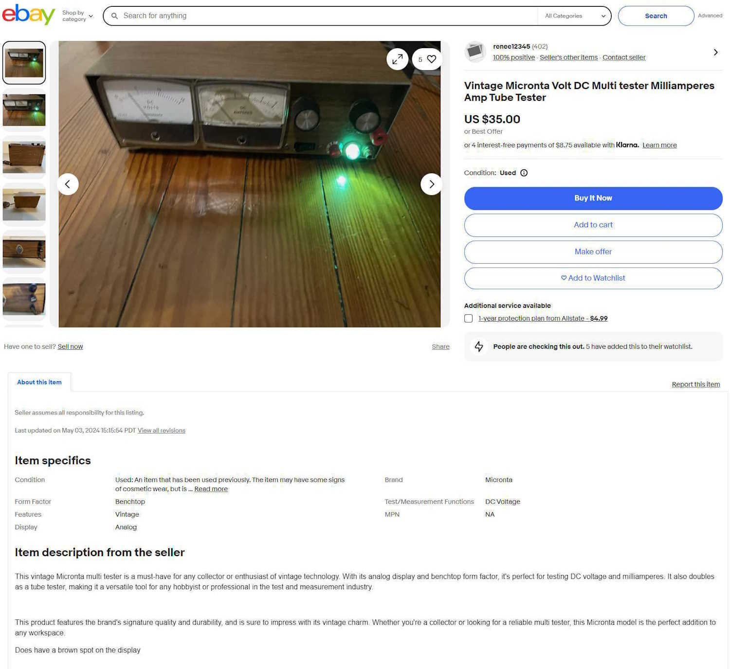
This is the first in a not-often series of wacky stuff I see on eBay. This one is a “Vintage Micronta Volt DC Multi tester Milliamperes Amp Tube Tester.”
It’s obviously someone’s homebrew power supply with Micronta (Radio Shack) meters on the front. Case would date it to the 70s, most likely.
AI has written a lovely line of BS for this device:
“This vintage Micronta multi tester is a must-have for any collector or enthusiast of vintage technology. With its analog display and benchtop form factor, it’s perfect for testing DC voltage and milliamperes. It also doubles as a tube tester, making it a versatile tool for any hobbyist or professional in the test and measurement industry.
This product features the brand’s signature quality and durability, and is sure to impress with its vintage charm. Whether you’re a collector or looking for a reliable multi tester, this Micronta model is the perfect addition to any workspace.”
I’m not sure how a power supply tests DC voltage, or even how you test a milliamp. Do you give it a quiz? If you have one joule per coulomb, how many volts is that?
It then goes on to say that it doubles as a tube tester. While I guess you could technically test the filaments of a tube with this, it’s nothing of the sort - any power source will do that for you, assuming it’s the correct voltage.
And then there’s the standard boilerplate that let’s you know AI wrote this, that of how it features the brand’s quality and reliability even though someone built this from their junk box - the only thing missing is how it’s widely used in the industry. It tried, though, with the “if you’re looking for a reliable multi tester…”
I got a giggle out of this one, not because of what it is, but of how it’s being described. It’s been for sale for some time, I don’t expect it to go anywhere soon.
I picked this little gadget up at the ACARA hamfest. Not because I plan on using it, but because it’s an unusual little thing and had a brand new book with it.
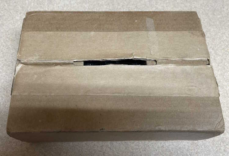
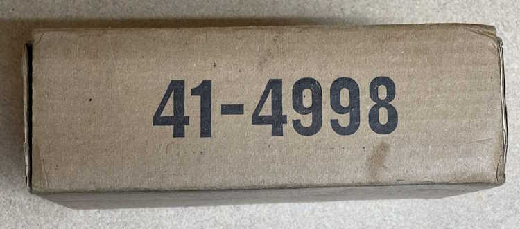
It’s a rather unassuming box with a number on the side.
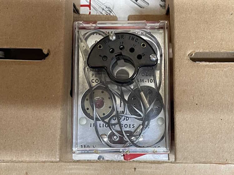
What’s inside is this little gadget, a power cord, and a book. The gadget:
It claims to be a Tricraft Products Corp SM-101 Filament Checker. I’m not sure how it works because there’s no instructions for the device. It appears to be used, but only very little. I can see some wiping on the contacts. The power cord was unrolled and rolled back up with bread ties.
I can’t imagine this was terribly useful, your VOM would have been quicker than getting out a power cord and plugging all kinds of little pins together in an attempt see if the filament was good.
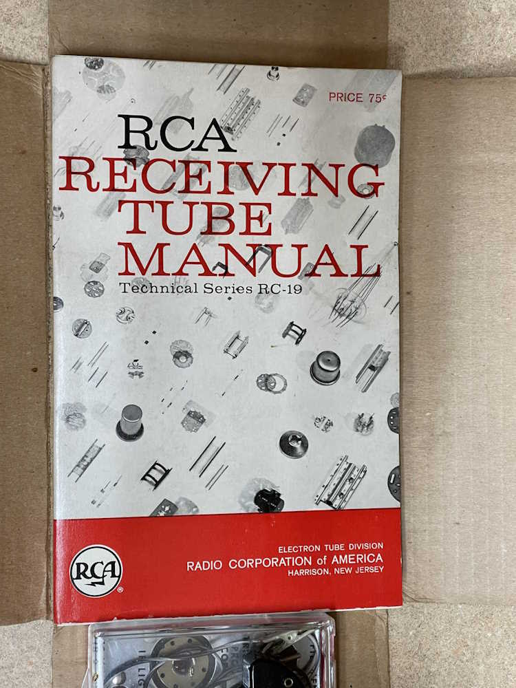
The real gem is the book. The RCA Tube Manual RC-19 from 1959. It appears to be unused, if a little dirty.
That’s worth the few dollars I paid for it right there. The other piece? A cool gimmick gadget for display.
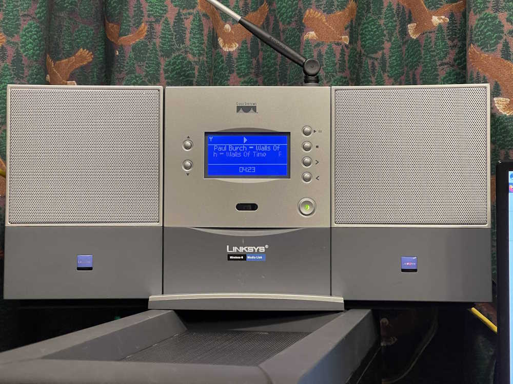
A few years ago, I wrote a piece detailing some fun I had with a Hamvention find, an ancient Linksys WML11B media player. You can find that article right here.
This is a device from the very beginnings of the Consumer Internet Age, and is evidenced by it’s early Wireless-B connectivity. Fortunately, it also offers an Ethernet connection. But…that’s about it. Modern browsers refuse to communicate properly with this thing’s web interface, seeing as how it was designed to be used with IE6. Modern HTTPS audio streams don’t work here because HTTPS was just starting to show up in the consumer space when this was made.
The weirdest thing is that a gigabit Ethernet port, which is usually more than capable of negotiating downward, doesn’t work well with this device. The device will simply stop playing and claim it has no connection after a short period, usually around an hour. A 100base connection will play for hours until the relatively fragile buffering in this device hits a hiccup and it stops.
That’s a real shame too, because this is actually a pretty good sounding device, probably on par with the Squeezebox Boom that came much later. While this device did have a now long-gone backend that would feed it station lists, it also had it’s own internal presets. You could use this thing and not have to worry about someone pulling a Reciva on you.
Seeing as how those squeezebox devices are still viable due to the continuation of the media server by Lyrion, I’ve decided to replace this unit with a used Squeezebox Radio that I purchased online for cheap. I’m not sure what to do with it, but the amplified speakers could be useful since they’re of decent size and good sound quality.


 Silvertone Battery Checker.")