This was an interesting chassis. Not because it’s anything unusual in what it does, but because it definitely shows it was the lower end of the spectrum. Heathkit, Knight, EICO - all of those showed some concern and care in how parts laid in the chassis. This one? Not so much. Things everywhere, parts flying from one side to the other, such a mish-mash of parts and styles and type. I’m still not sure if this one was factory built or kit built, seeing as how it has pop-rivets for everything mounted on the chassis. Seeing as how some of the parts interfere with others, it probably was kit-built.
What do I think about this device?
There wasn’t really anything different about this rebuild except that it required a lot more thought on how to place things, I couldn’t simply move strips around a little or remove parts without drilling them out. That was quite the pain, but it was worked through and eventually everything was re-installed.
I took the opportunity to use some new sleeving I’d purchased, since many of the parts had spacing far longer than anything you could purchase without special dispensation. These parts had a lead j-hooked on, and run to their connection points. I tried to stick with more modern parts like 1% films, good capacitors, and the like - except for the one used in the leakage circuit. This 1.8MΩ @ 2W was hard to find, so I just chose another carbon that was closer to the marked value. It’s not really like it matters, but it is what it is.
I couldn’t get the unit to do much of anything. The eye would close when a part was attached, so something was happening. I’m not sure if the instrument is just that low on the scale, or if the parts I have are bad to the point of being unable to be tested by this device. Regardless, it didn’t seem to do much, and that’s pretty much what I expected. This wasn’t about an accurate instrument, it was about the rebuild process.
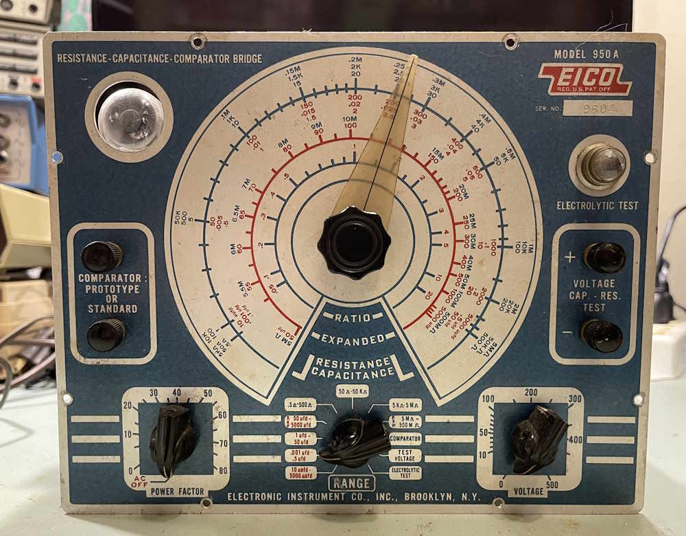
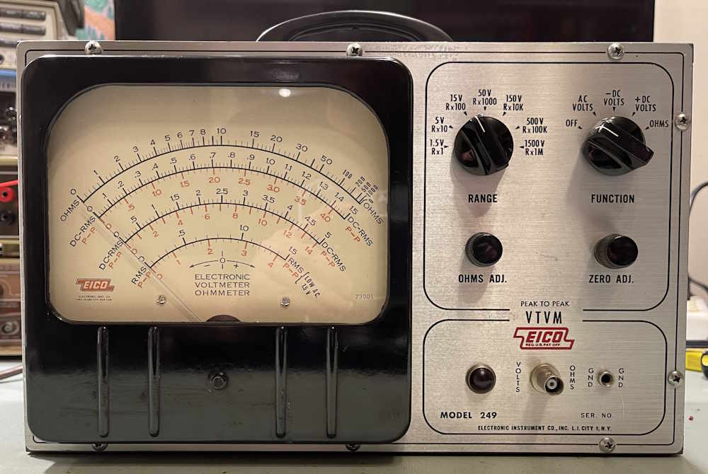
That’s all. This is just a footnote shelf queen. Next up is the Simpson 715, finishing up the rectifier section. After that, an EICO VTVM finally gets it’s time on the bench, and perhaps an EICO 950A - assuming I can find schematics for it because that one is a mess. Stay tuned!
Unfortunately, when hitting some of these parts with high heat, it tends to drive them (temporarily) back towards their actual values - especially in the case of carbon resistors where the heat may drive out some of the water the part has collected over the years.
In this case, the manufacturer provided a lot of surplus RN-type components, as the device is mostly WWII surplus. These held up well over the years, and probably were fine to leave in place - had they not been worked over when installed. Carbons…yeah, those probably weren’t anywhere near what they are now due to the 80W iron drying them out. Capacitors, for the most part, were well out of any tolerance, assuming there was a tolerance marked - or even a value marked at all.
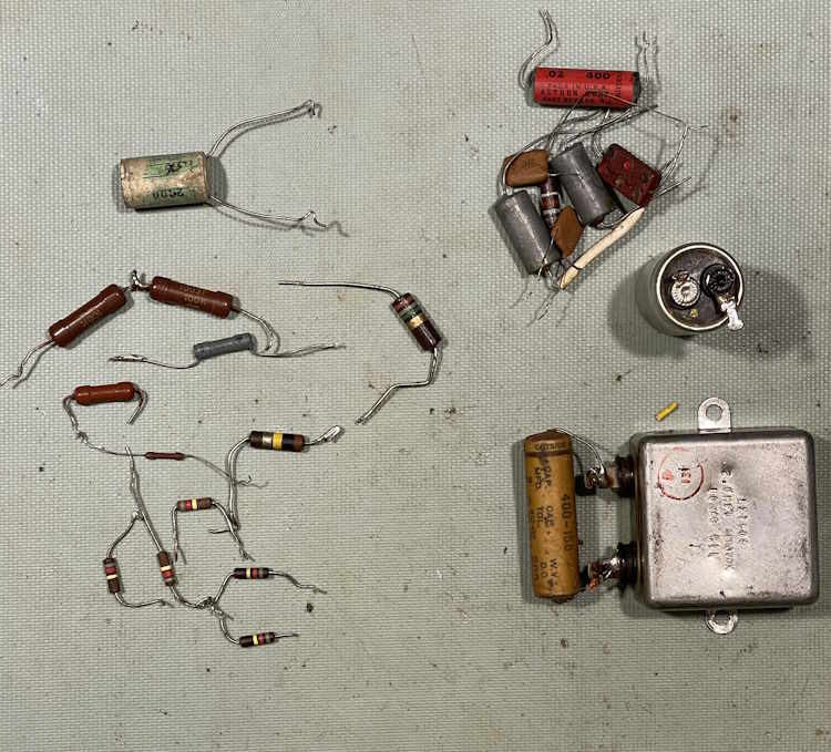
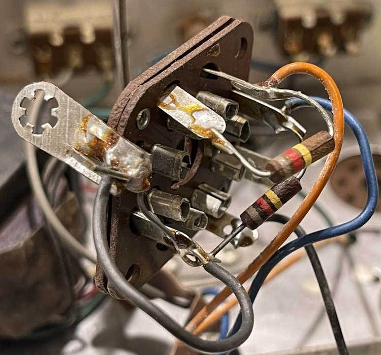
Everything except the 68.1KΩ resistor is in this picture. That part was much like the 750KΩ, some small RN-type that I’m not familiar enough with to identify. It’s probably on the floor or behind some other item on my bench, hidden away due to size. Everything else is right here.
How did they test?
Capacitors, for the most part, are well out of anything I’d call tolerance unless you’re -20/+100. Resistors were mostly pretty good, being mil-spec parts. Carbons were probably better than expected because they were hit with a lot of heat - perhaps I’ll set the 820KΩ parts aside and see how they perform in a year.
In the chart, the following notations are used.
RN - Resistor qualified to MIL-R-10509
WW - Wirewound
DB - Dogbone, probably also RN
CC - Carbon Comp
A part of note
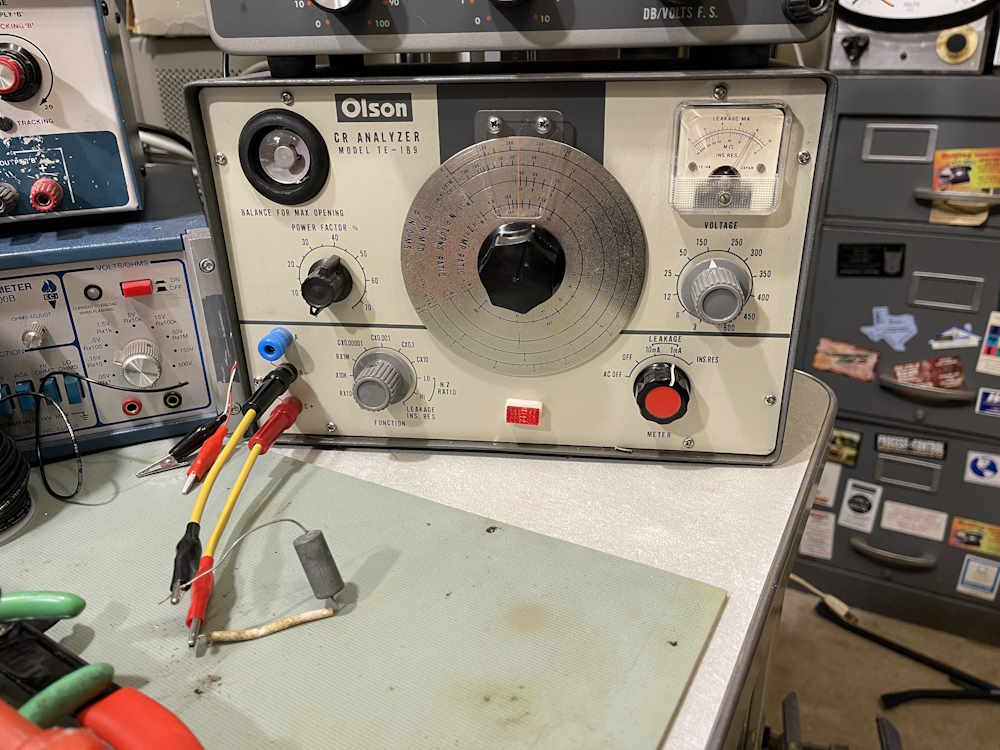
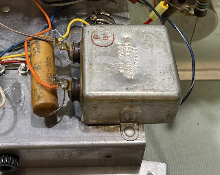
There were two weird metal can capacitors in the unit. There was no label on them, any paper label having come off probably sometime before I was on this earth. Placement suggested they were 0.02μF but they didn’t read anything like that:
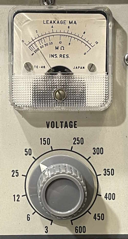
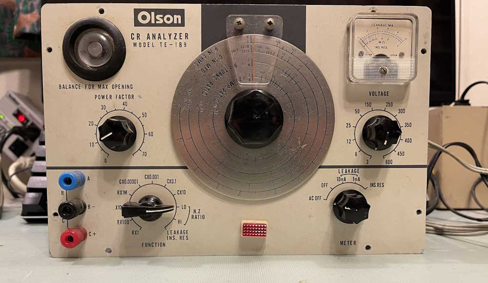
I hooked it up to my Olson C-R bridge, but didn’t get any eye opening at all. I decided to run leakage and see what it did.
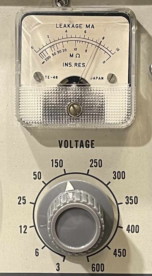
150V, and almost 8mA of leakage? This thing is shot.
Even at 50V, it leaks.
So…whatever these are supposed to be, they aren’t doing it anymore. I’ll toss them in the bin as known leakage test parts.
It’s time to power up the unit. I brought it up with a death cheater, and B+ settled in around 130VDC.
That’s probably about right for this, so I replaced the death cheater with a normal cord:
And brought it up assembled and stuck a capacitor in it.
Yeah, it doesn’t do much. Either all of the parts I chose are unable to be tested by this device due to bad components or something else, it didn’t do anything. The eye does close upon part connection, so something is home inside. Just…who knows what it is.
But never right after you did the work. You have something called confirmation bias that that point, that means that you just put it there so it must be right and you’re not going to catch mistakes. Take some time away from the unit, maybe even the next day. You want to kind of forget what you just did.
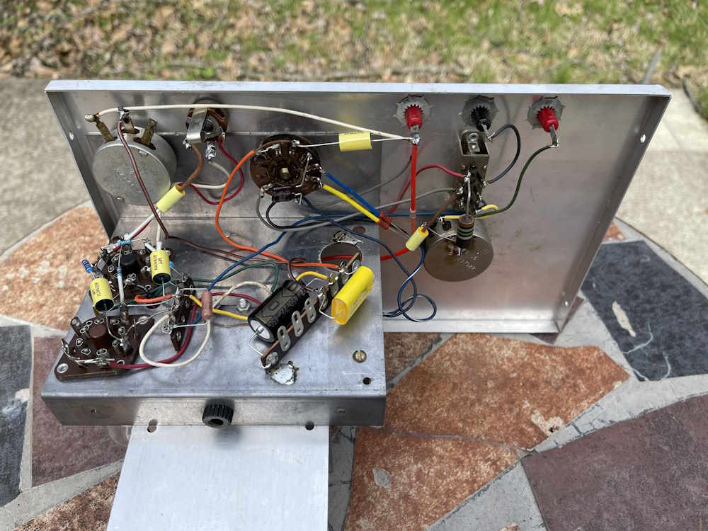
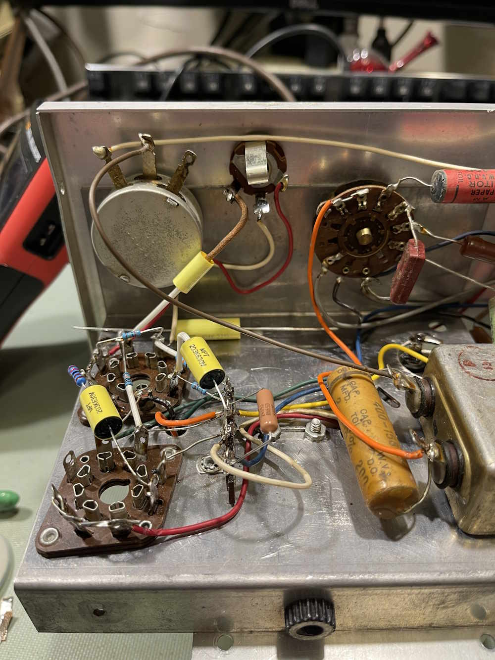
Here’s the chassis, completed so far:
It’s still messy, but less messy than it was, and all of the parts are of known values.
Soldering
Soldering a chassis like this is always an adventure…I do each part in sections, so multiple components might get mounted before I solder things. Sometimes, I don’t solder things right away because I’m thinking that terminal may need something from a later section…regardless, sometimes things do not get soldered. There were a couple here:
Misplaced parts
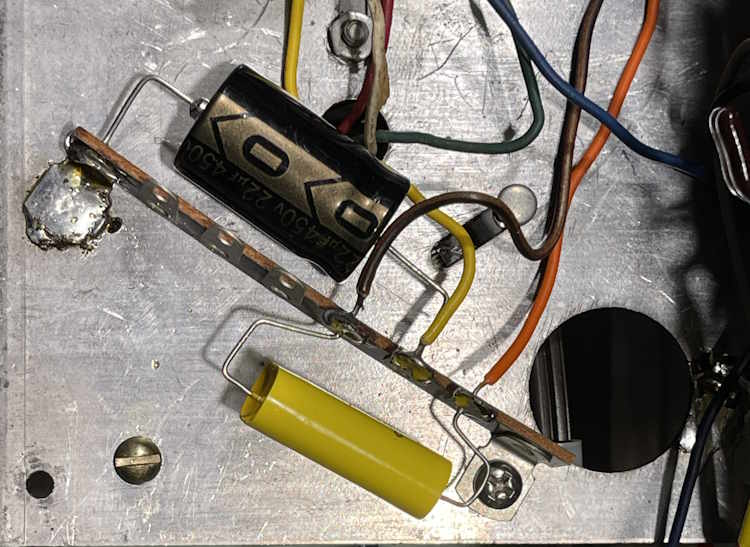
There was one part I put in the wrong spot. The 180kΩ resistor that’s behind the capacitor in the foreground attaches to the lower terminal of the potentiometer in the background. That should have went to the top terminal. This was an easy fix, unsolder, trim the lead, and re-solder.
Missing parts
Here’s the jack on the back of the unit.
You can see there are two wires on the terminal. There’s also supposed to be a capacitor on that terminal to ground, and that part was laying right behind the unit in the tray I used to hold components. Here it is:
I was going to take it back to a terminal near the AC input, but eh. I took a terminal strip, made it into a 1 lug unit, hit it with 180W of iron and made that my new tie point. It’s a bit messy, but that solder isn’t going anywhere.
Checkout is complete. Everything is now where it should be going, and is soldered properly. Time to move on to the power-up.
Now that most of the top of the chassis is out of the way (yah right, I forgot some stuff and had to correct some wiring errors from the previous owner…) it’s time to do the bottom of the chassis.
There’s not much to say about this, so here are the rebuild images in no particular order save I tried to follow before with after in a particular section of the unit.
That’s pretty much everything except for the power cord. That comes at the very end, SICo just laid the cord over the chassis and through a tiny hole. There’s not enough room to actually pull the cord’s head through, so the back and power cord become one assembly. I’ll use a death cheater to bring it up after checks.
This thing had a rough life. It doesn’t really work right now save that it lights up and makes glow. Did it ever really work? Well…since I just wrote that, I think you can probably guess what I mean.
I can’t say I’ve seen a device that has corroded wire like this one does. Not all of them, just some.
It’s hard to see, but it’s speckled with green. I checked wires as I went, some needed replaced, some were replaced just because they were in bad shape otherwise.
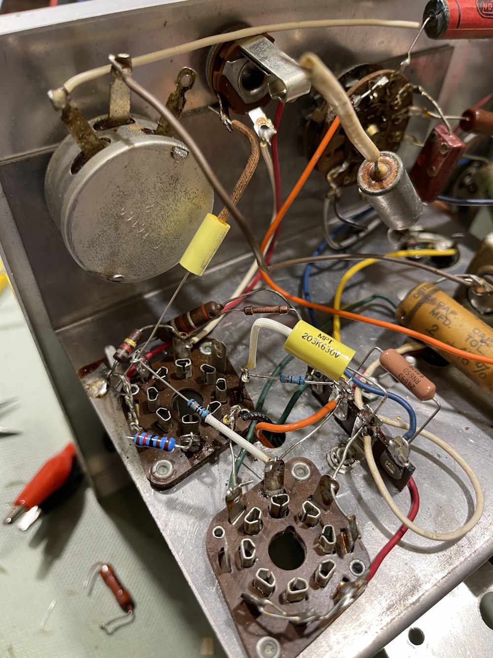
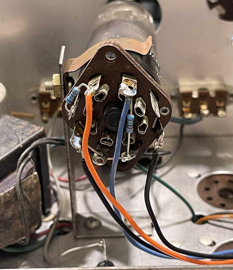
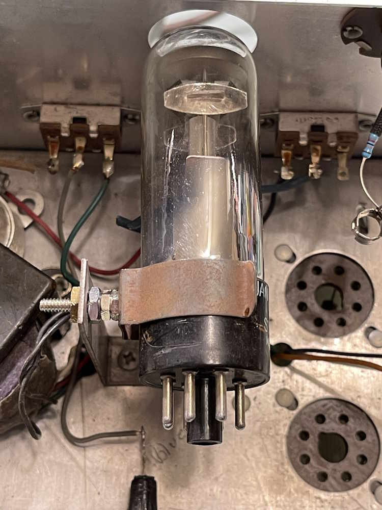
The eye tube socket assembly.
Everything here was attached decently, but stuff just looked bad, and these wires were corroded.
Some new resistors and new wire, and it looks better. Still needs a bit of dressing, but that comes last.
The original builder put the eye tube at a weird slant. While the bracket itself can be moved on a slide, doing so puts the bolt for the bracket up against a terminal strip underneath because it was mounted opposite of how it should have been. That was corrected by just using a longer screw and some nuts as spacers. It’s not like this thing is going anywhere, so mechanical stresses aren’t a concern.
That’s all for the eye tube.
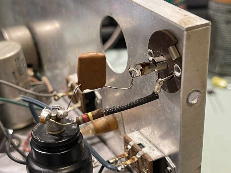
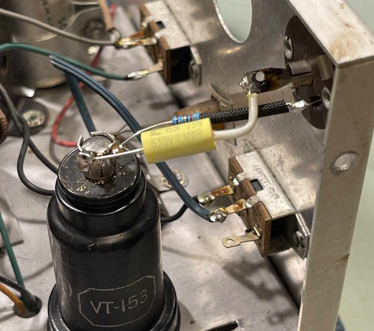
The grid cap for the 12C8.
This is the “signal tracer” portion of the unit, and it uses a WWII surplus tube, the VT-153/12C8. This tube was designed for radio service, and exposes one of it’s grids on the plate cap. That’s where audio is fed in for amplification. There are two parts, a resistor to ground that provides bias for the grid and a blocking capacitor for the audio so you don’t get DC in your device that’s under test.
That was easy enough to re-do.
Fairly standard work, there’s really nothing of note. It’s time to move on to the main body of the unit, and all of it’s “none of this matches anything you wrote down!” mess.
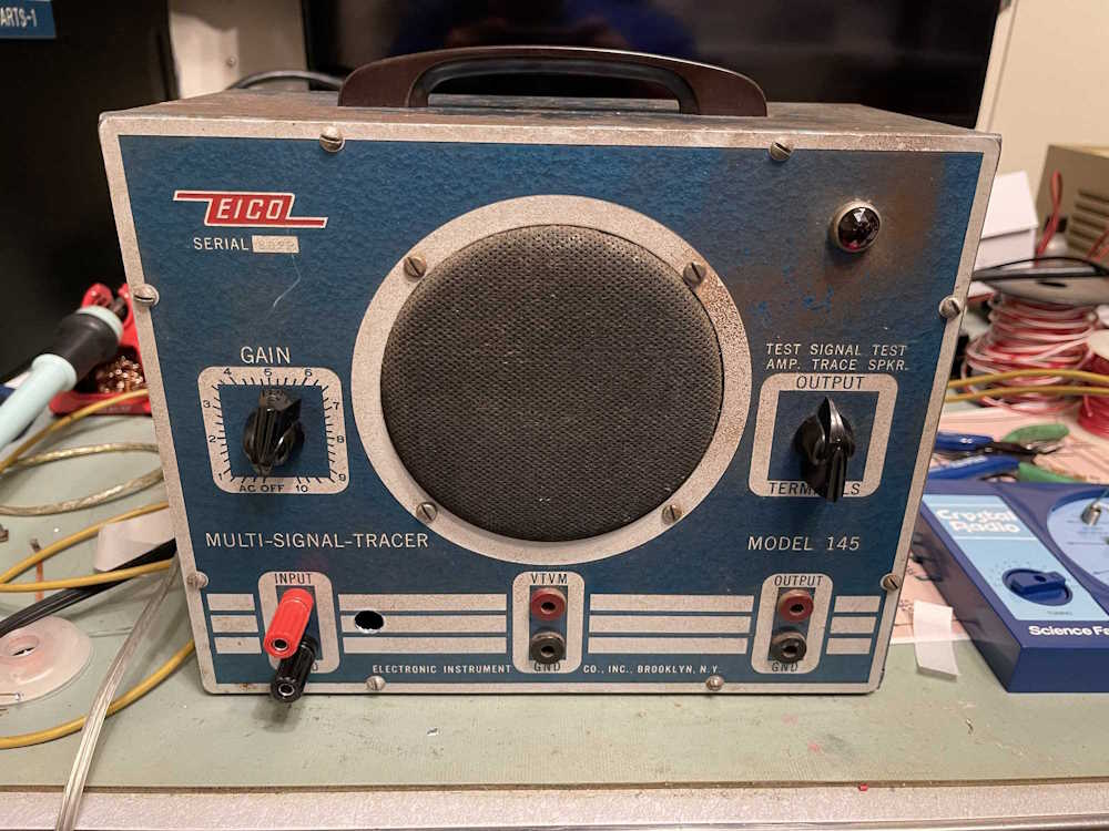
It’s been a while since I’ve done an eBay junk post, so it’s high time. The amount of AI slop has toned itself down a little bit, the wild descriptions of a few years ago have settled into a generic “A valuable and quality device” for most things. No, your hobbyist signal generator from 1963 isn’t widely used in industry.
There are other things on eBay that are quite amusing, however. One of those are these listings for a Delco Vibrator. No, that’s not a toy you have to go to those shops downtown in back alleys for, it’s an electro-mechanical part that was used in automotive radios when tubes were still king. It’s a relay that turns itself off, so it just sits there and vibrates at whatever speed it can, turning power on and off. It’s a mechanical pulse generator, and the pulses it generated were fed to a step-up transformer in order to make B+ for the tubes. There are modern solid-state equivalents if you want to rebuild an old car radio, but sometimes you want to open a can and stuff it so it looks like the OEM part.
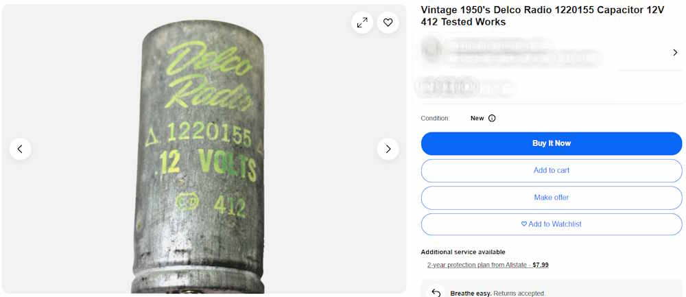
So why post these? They’re amusingly bad - and in some cases probably an outright lie. They’re all Delco 1220155 Vibrators, and a few minutes online would tell you that. Names and prices have been removed to protect the guilty!
Part #1
This one purports to be a “Delco Radio Speaker Capacitor???” Not sure what a Capacitor??? is, but here’s one if you need it.
According to the seller, it’s a double-DIN radio as well. It’s from a working radio to boot.
Part #2
This one is also a capacitor, and the seller has tested it and found that it works. I’m confused as to how this happened, but apparently - it did. Is the seller just writing things there to fill space? Even Mister Owl doesn’t know the answer to that question. I mean…how does it work?
But you get some dust from their warehouse!
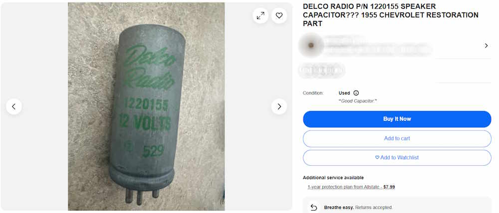
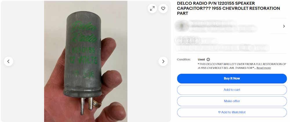
Part #3
This is probably the best one. It is from a listing that purports to be an auto parts reseller, and that the unit was left-over from a recent automotive restore. It, like the first one, is a “Speaker Capacitor???” Here’s an idea - if you’re selling auto parts and restoring cars, wouldn’t it be in your best interests to actually, oh, I don’t know, know what you’re selling?
While I could see where an inexperienced seller would make a mistake - these do look like capacitor cans - all you need to do it spend a bit of time online to find out exactly what this is.
One of the things that has been suggested to me is a quick way to find all of the major projects that have appeared on this blog. The easiest way for me to do this would be as you see it here: a single post, similar to hamfest pictures, that collects all of the major device projects that have appeared here.
This hub contains all the the things I am currently working on, or have completed. New projects that are still underway generally appear at the bottom of the post, and the post will grow as more are added. The only things that are not here is a few small things that I did for other people, or the home automation stuff. You can find the latter in a new category on the sidebar aptly labeled “Automation”.
There’s a permanent link on the sidebar that will bring you directly to this hub post.
Click on the title of each item to be taken to that project’s hub.
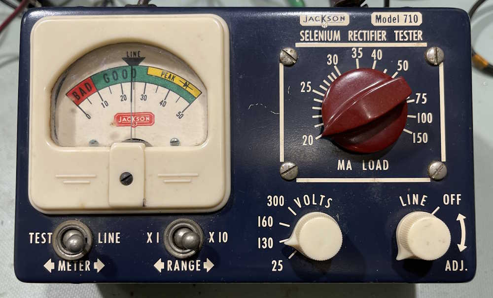
Here’s an odd little device from a different age…this is a Jackson Model 710 Selenium Rectifier Tester. Manufactured by the Jackson Equipment Company of Dayton, Ohio, this is a single-purpose instrument in an attractive case. It was purchased at the Columbus Hamfest for $1.00.
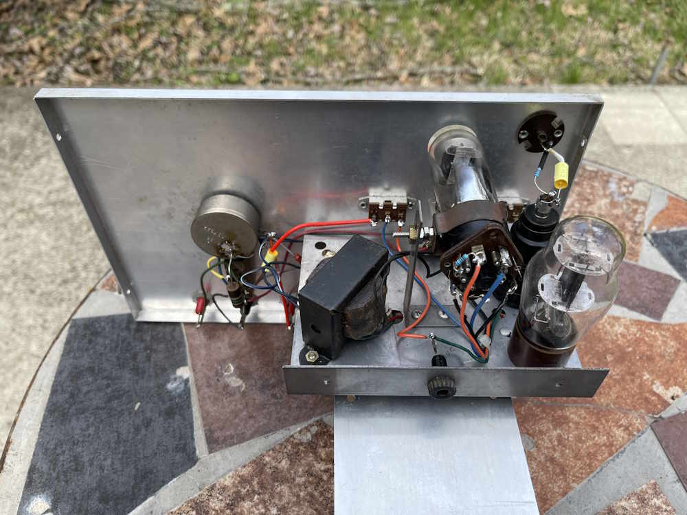
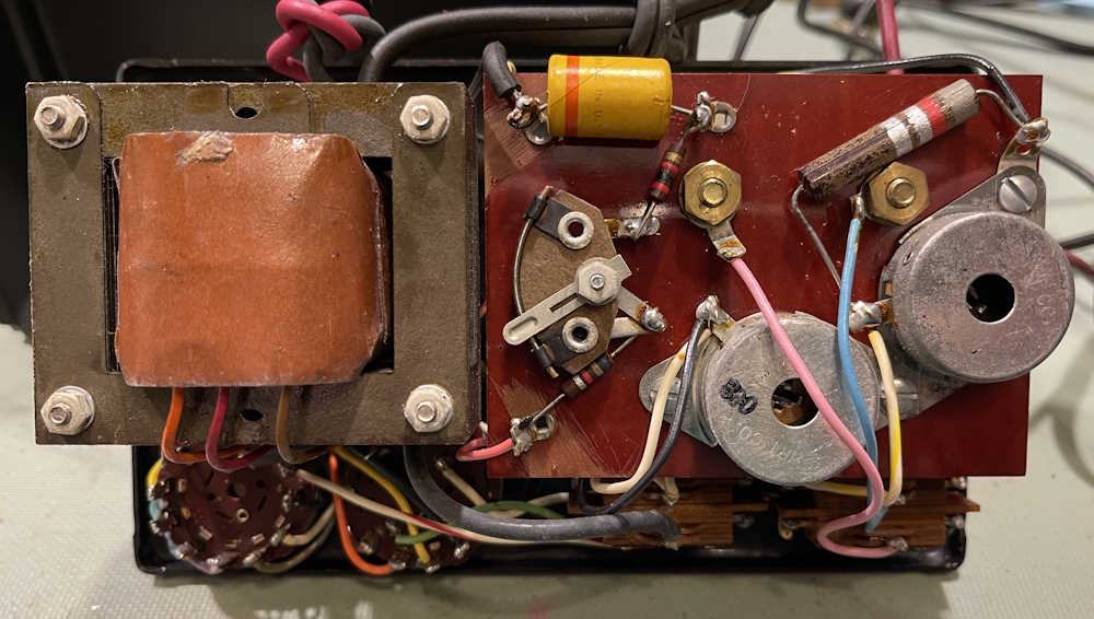
There’s not a whole lot inside of it:
It even has it’s own little selenium stick rectifier at the top.
The business end is the massive multi-tap transformer inside the thing. This is what’s giving it weight.
It also has this cutely named “sele-rater” attached to one of the crumbling leads. I assume this is so you can determine (by physical size) what kind of rectifier you have in your device.
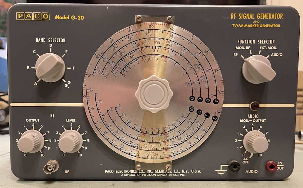
So, does it work? Here’s a selenium rectifier removed from the recent PACO G-30 rebuild. I know it’s still a good device, as it was pulled from a working unit.
Hooking it up and trying every combination of switches I can, I get no deflection on the meter. Ok, so what’s on the outputs of the device?
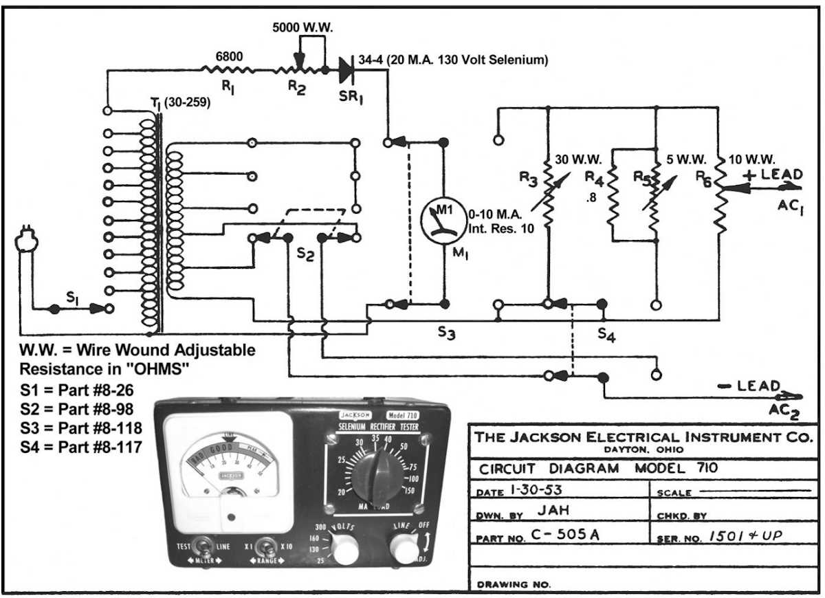
There’s pretty much nothing on the output, whereas there should be 130V under test. That tells me the selenium stick is probably bad. No surprise.
What’s going to happen to this? Well, it goes back together for now. It’s not a terribly high priority for me as it’s more of a “that’s cool” device. If I can find an appropriate rectifier at a show, I’ll drag it back out and fix it just to make it work. Otherwise, it’s an interesting display piece, and nothing more.
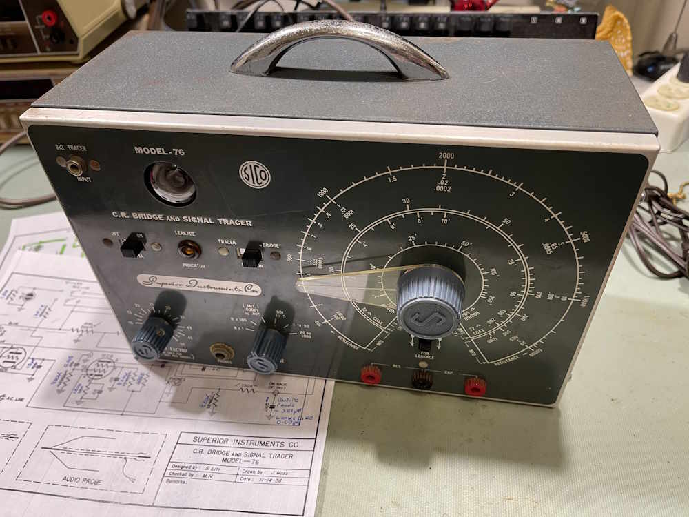
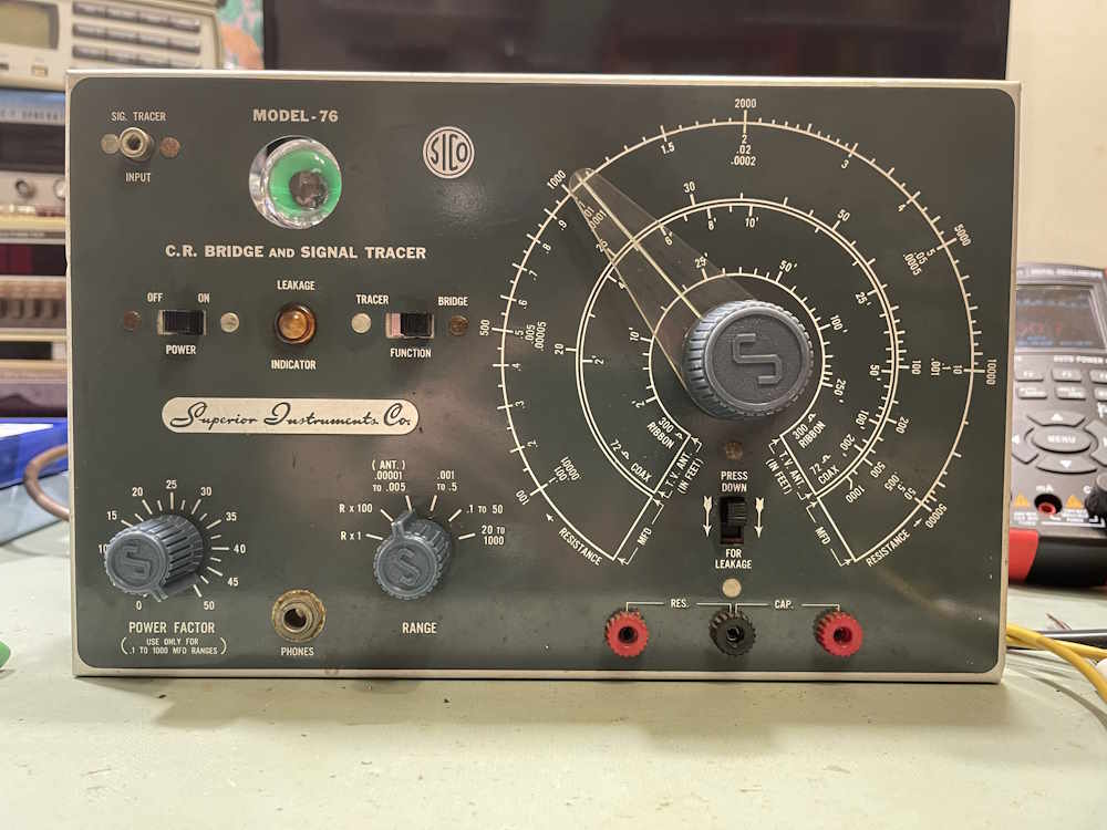
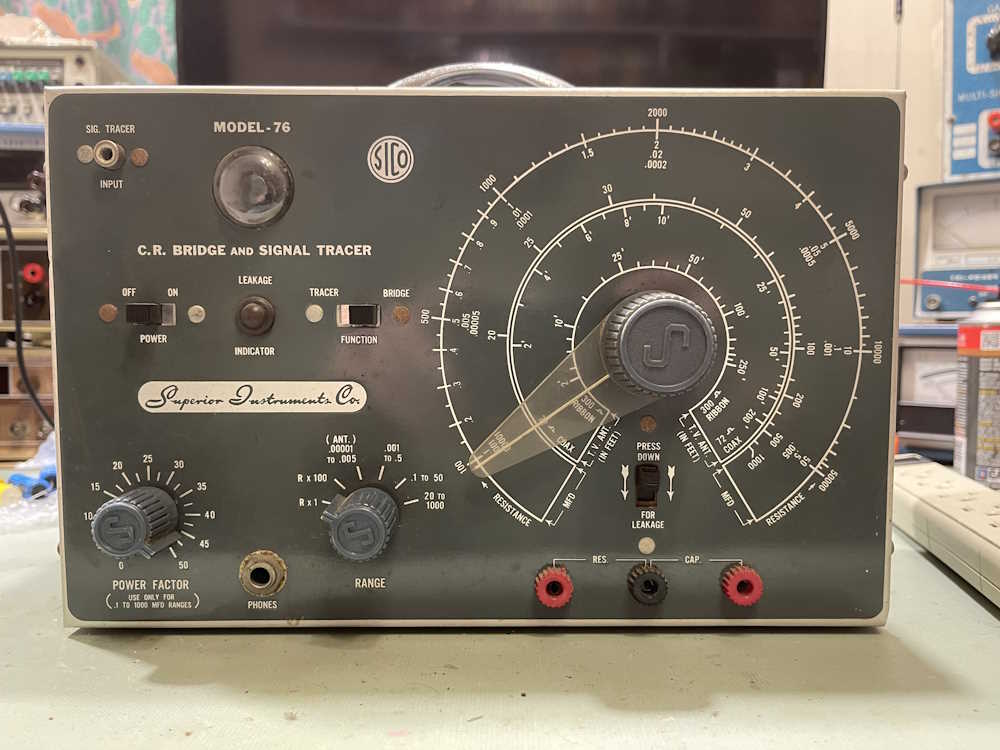
A month or so ago, I made a post about this device, the Superior Instruments Co Model 76 Bridge and Signal Tracer. The unit combines a single tube headphone amplifier for tracing with a bare-bones CR bridge for capacitor testing. You can find that post here: https://wereboar.com … cent-acquisitions-1/ if you’d like to read it.
There’s a lot going on inside of this device. Much of what’s going on inside of this device is of the “What?” variety as the schematic and device itself do not match very well, if at all. The basic components are there, but the actual values and some of what’s there isn’t.
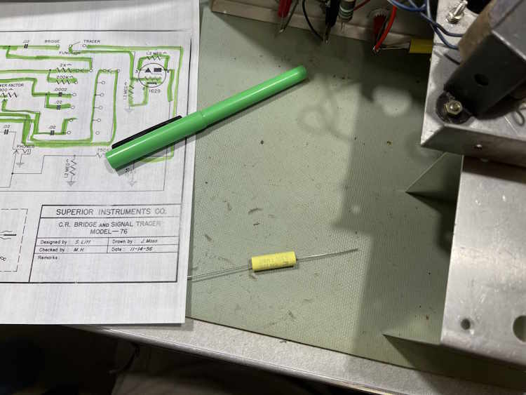
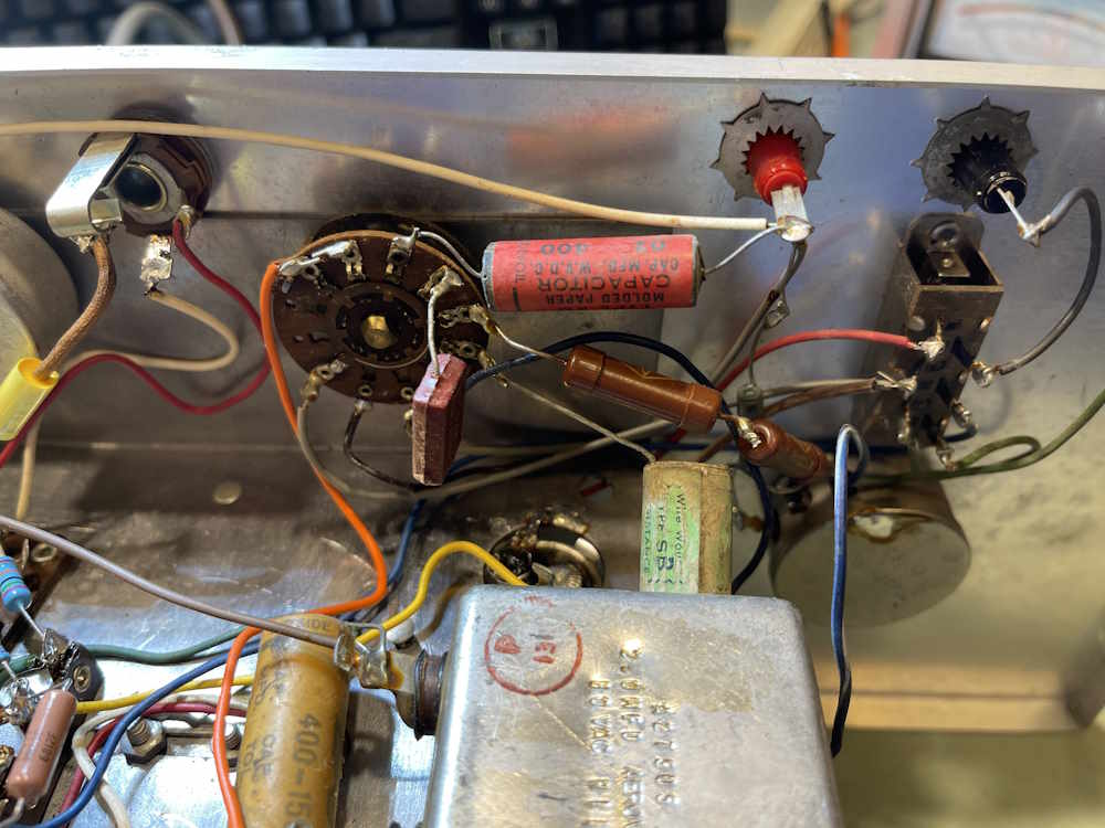
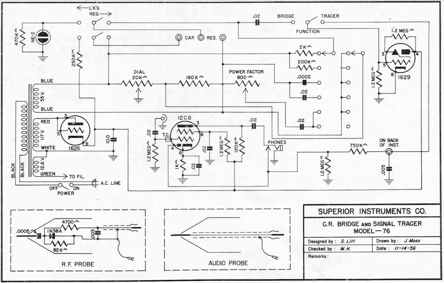
Here’s the device schematic, courtesy of the BAMA archive:
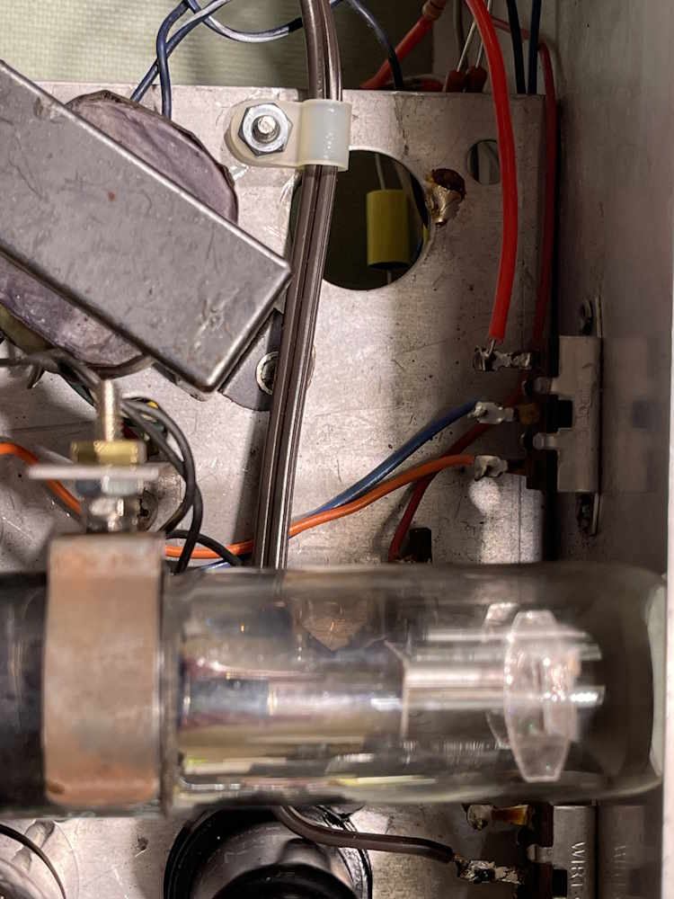
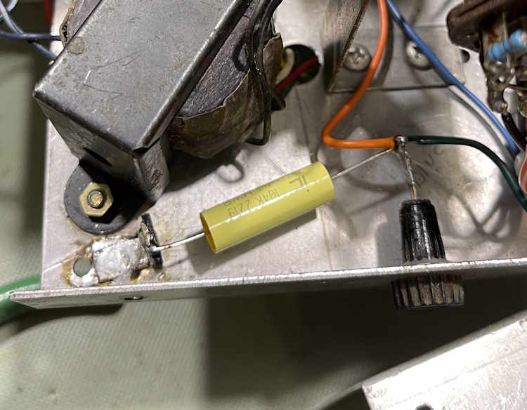
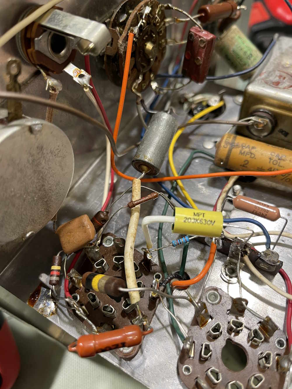
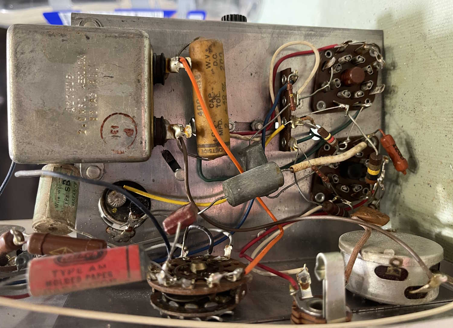
That big motor starter capacitor with the 0.2μF wax-paper across it? On the schematic but listed as 0.02μF . Those two metal cans with no labels in the middle? Not on the schematic…what even are they? They look like capacitors but one measured nothing, the other measured 17μF with a capacitor analyzer. I don’t know that this was available as a kit, so either the OEM just stuck stuff in as needed to solve problems, or someone added these later. I’d go for the “added later” due to the multiple types of sleeving and the fact I’ve seen another one of these that didn’t have those parts.
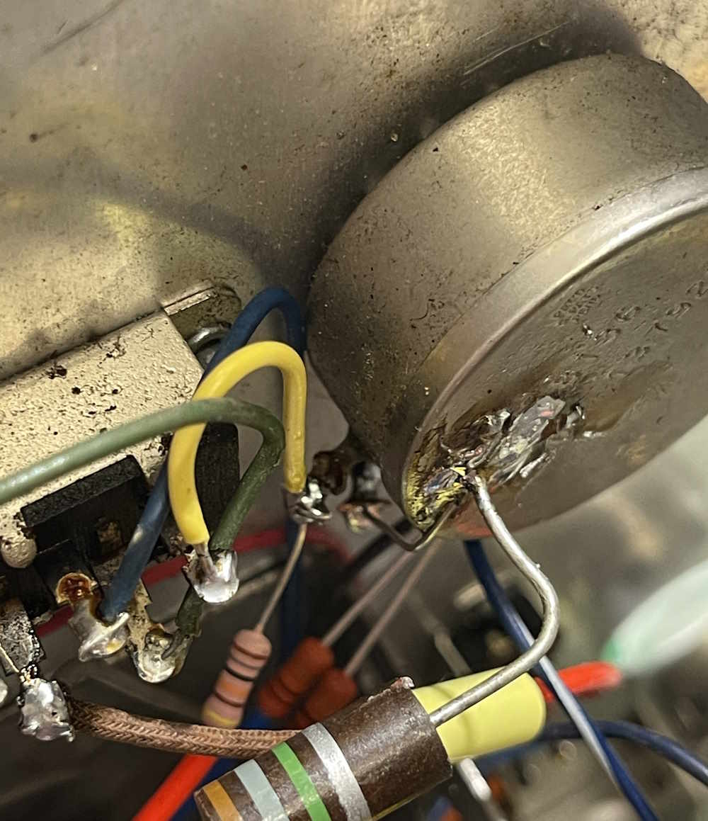
But there are other things going on in here.
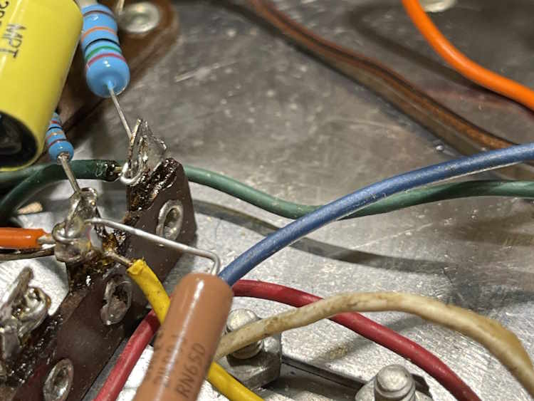
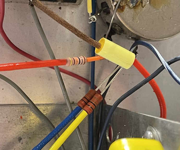
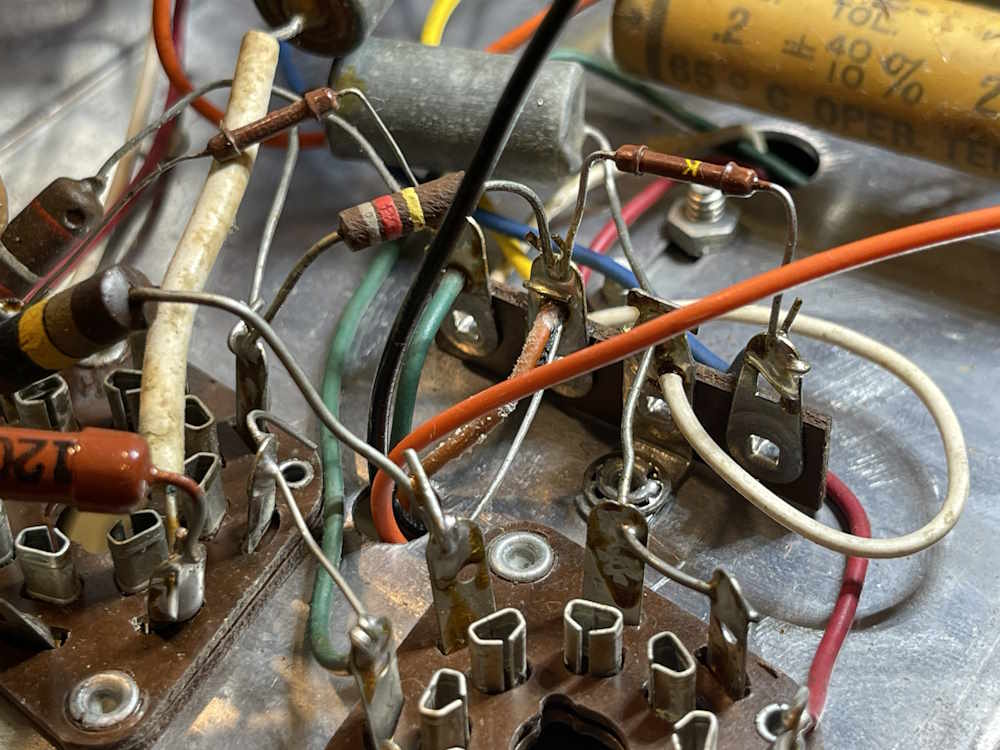
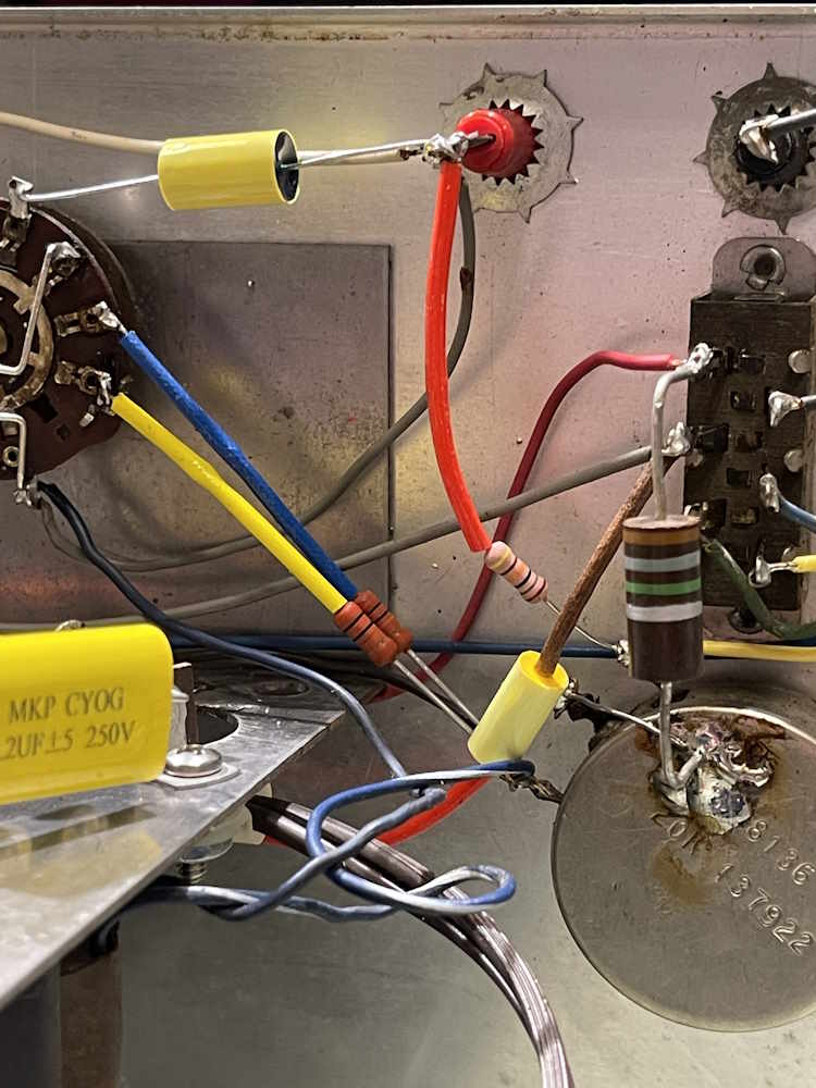
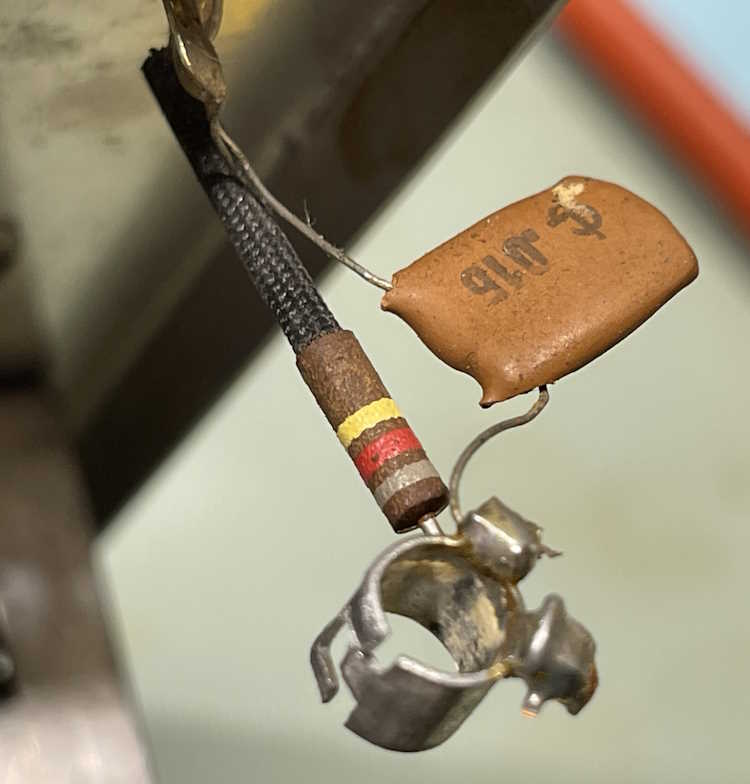
Those are the parts connecting the grid input of the VT153/12C8 tube to the input jack. The schematic states those two parts should be 0.02μF and 1.2MΩ, but instead they are 0.015μF and 820kΩ. Many of the 0.02μF parts in this device are actually 0.015μF ceramics.
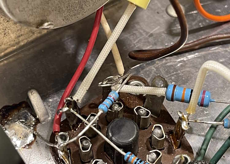
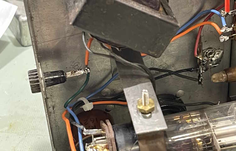
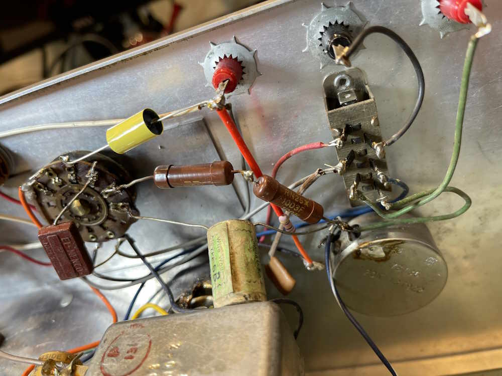
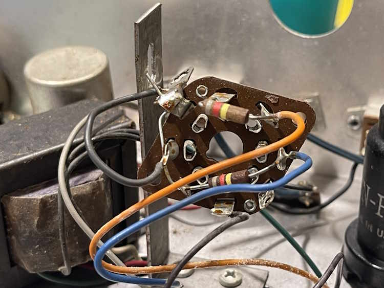
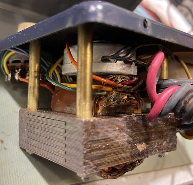
Here’s the eye tube socket. Those resistors are also supposed to be 1.2MΩ but instead are 820kΩ. Like the capacitors in the previous image, many of the 1.2MΩ resistors specified are actually 820kΩ.
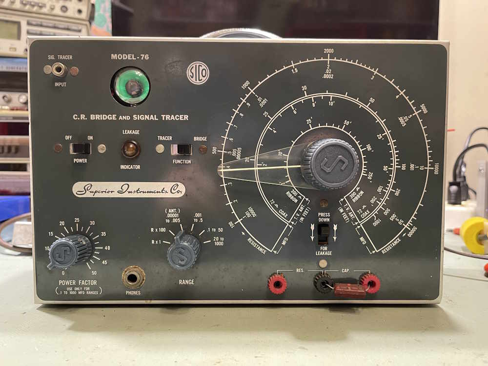
It’s obvious this device was built from surplus WWII components. The USN tubes, the RNx resistors, and the oddball parts are all surplus, so it’s no surprise that things don’t match here. However - it’s going to take some doing to rework this item as I can’t simply order things based on the schematic.
The device is working, so there is that. I’m going to work with it a little and try to produce a corrected schematic before proceeding. Stay tuned!