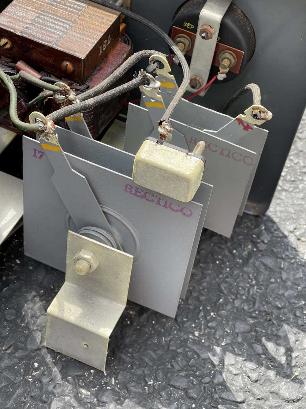
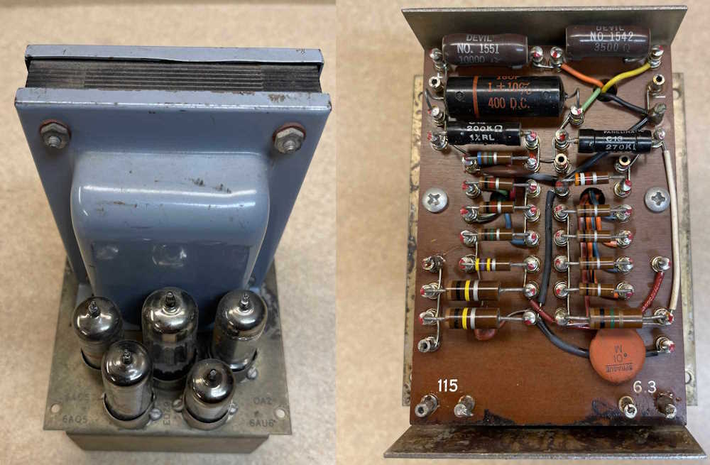
I recently picked up an ancient PACO B-10 “Power Supply / Battery Charger” from the Columbus Hamfest. I wasn’t sure what was in the thing, but turns out there’s not much.
These giant selenium plates, however, are a thing of ancient beauty. The whole thing looks like it’s era, a mash of wire, transformers, and rust. Stay tuned for a more complete teardown and other photos of this device.
I brought home some things that I didn’t need, but isn’t that the point of this kind of show?
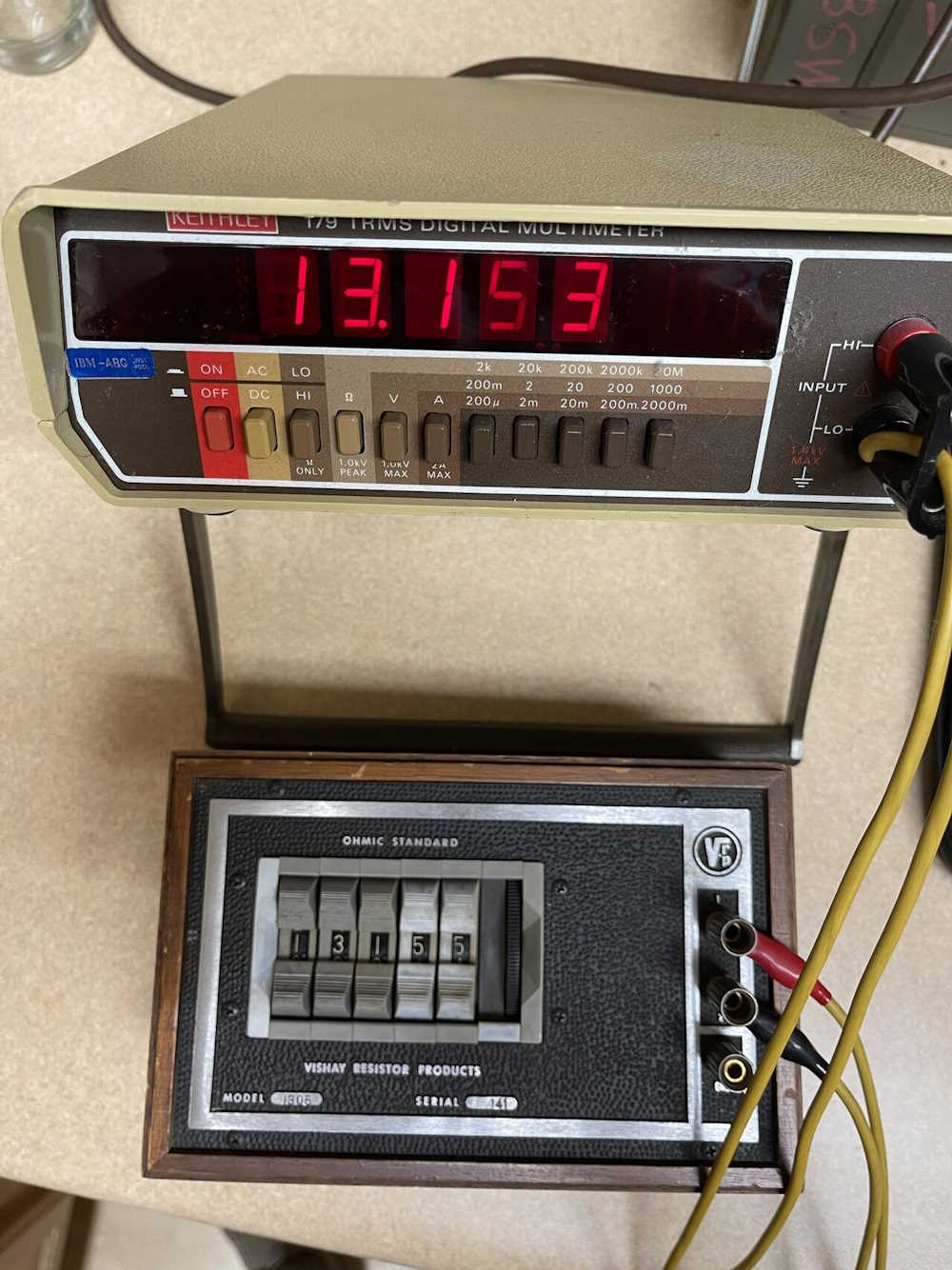
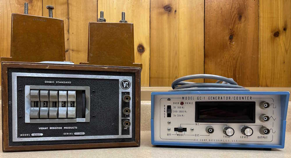
A Vishay decade box and a frequency counter / generator. They both seem to work well enough for the age. There’s also some high-voltage mica capacitors sitting on top of the decade box. Those were a buck, and I said why not?
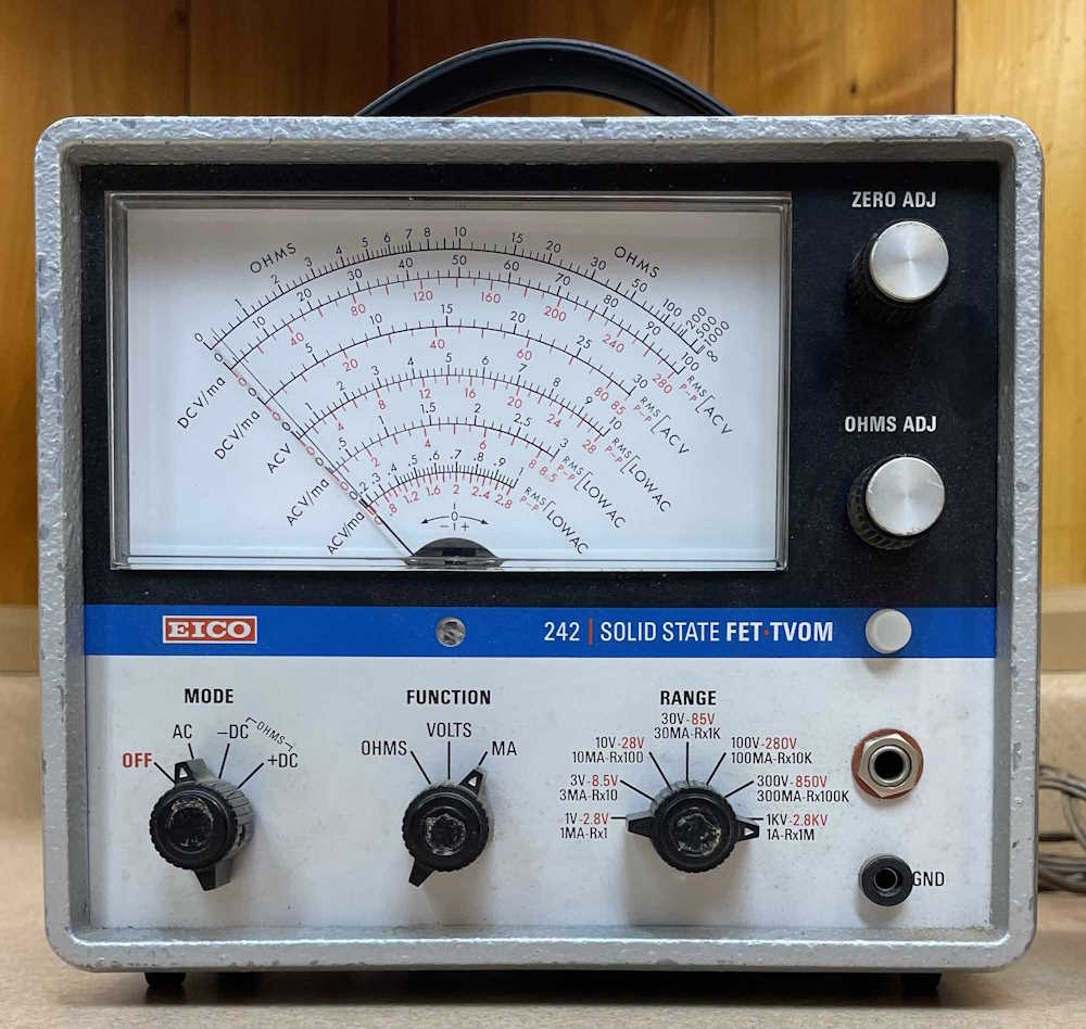
I can’t go to a show without bringing home at least one meter. Unfortunately, this one seems to have some issues, it will zero but not read. I need to open it up and make sure that any batteries left in it aren’t corrodeedoodled all over the place. It had a lot of bad resistors in the divider chain.
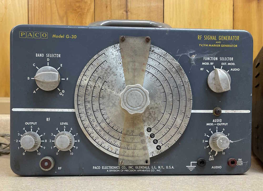
This PACO generator is the same as one I have in better condition. This one is a $5 parts unit.
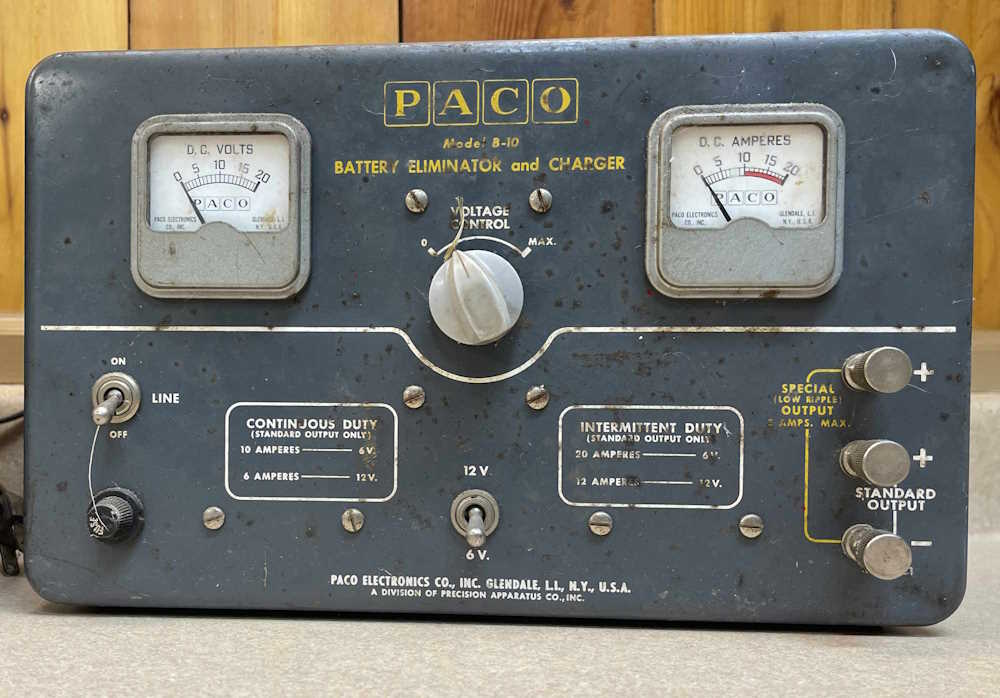
This is a PACO power supply that came from the same vendor as the generator, also $5. It’s an interesting piece, being an early bench supply for audio work, but in reality it’s a glorified battery charger. Stay tuned for a teardown on this guy. It eventually got passed on to someone for scrap. That’s what it’s worth!
No idea what this is, my fellow show-goer suggested it was some sort of early electronic switch for process industry. He’s probably right, but I got it simply for the cheapness of a 250VAC transformer that could be reused. I tore it down for parts.
That’s it for this year. I’ll be posting show pictures, and some other, recent engine shows as soon as I can get the images cleaned up.
One of my fellow show-goers was talking about taking some of the audio gear he collected to Dayton in 2025, and we’ll set up a table on the flea market. This sounds like a cool idea to me, I’ve attended shows but never had a sales table.
In the spirit of things, I took a look at what I’ve collected over the years that’s never going to go anywhere, and there’s a bunch. It’s time to start cleaning out, and I have a bunch of things that could go. Where does it all come from?
See you there, and maybe you can take something home! It’s cheap cheap cheap!
(If you see something you like, drop me a line on LinkedIn and we’ll see about a deal!)
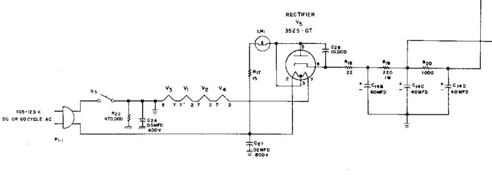
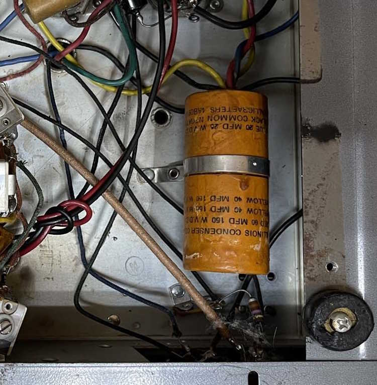
One of the things I picked up at Dayton this year was a really nice example of an S-38C multi-band radio. Completely untouched inside, it of course has bad filters. That’s par for the course for one of these. (It probably also has some silver mica disease, but that’s another day’s problem!)
Replacing them is easy enough, but it all depends on how you want to do it. Some prefer to keep it original, opening up the can on the multi-section device and putting new components inside. Others just wrap capacitors wherever there’s a place to put them. I’m thinking of going a different direction with this one.
Most of Hallicrafters low-end transformerless sets used similar multi-section capacitors and dropping resistors.
(Schematic from the Riders Manual.)
Some, like this one, used a 220Ω and 1kΩ resistor, others (like the S-95) used a 470Ω instead of the 1K.
So…why not create some sort of universal PCB that can drop in and replace all of the filter capacitors, sans the cathode bypass capacitor used in the audio stage of some of the units?
I had thought of using axial devices, but those can get expensive. What’s not expensive, and are compact and readily available? Surface mount parts. A small board could be created with three capacitors and space for the two dropping resistors, pre-assembled (or partially, depending on what you’re trying to fix,) and either double-side taped in or bolted down. The board wouldn’t need to have any through holes, wires could simply lay on pads and be soldered down. 5W resistors and 160V capacitors exceed original specifications, and would be easy to install on the board.
There’s certainly plenty of room in the device once the original can has been removed.
Wow, those feet are in bad shape…need to find some replacements!
I know that idea will offend some purists, but that’s not my concern here. I want to get the device back up and running with good quality parts that fit in the space required, without drilling a lot of holes or simply shooting parts all over the place.
I just need to brush up on my PCB skills, and lay out the board for sizing. Stay tuned!
This is a benchtop test box I picked up at the Breezeshooter’s Hamfest this past June. It’s simply a switched, fused outlet with some indicator lamps and a current meter. It proclaims itself to be a Waage Electric Model 066, “All Purpose Tester.” It’s in eh shape, and probably sat on someone’s bench for decades.
The cord is in good shape, which is surprising for the age, but both the neon pilot lamp and the little 7W peanut bulb for the circuit test are dead. It was probably “on” for most of it’s life. The neon bulb in the pilot doesn’t even do the flickering thing at this point.
Everything seems to be mechanically working, the switch snaps with a nice thunk, the meter pointer moves but needs to be adjusted, and all of the sockets are intact. Of note here is the Edison Fuse - no 3AG glass fuses here!
The inside is pretty clean, overall. I can immediately see the cord appears to have been replaced because of the way it’s put on the screw terminals - it’s unlikely the factory would have shipped it all birdcaged out like that. So that’s probably a new(er) cord.
Of real not here is the small gauge wire used for the device. The orange wire appears to be about 22GA solid - that’s not going to handle the 15A this thing is supposedly rated for. It makes me wonder if this thing was completely redone at some point in time, as there’s a mix of thermoplastic and cloth-coated wire in this. It’s of an age where everything would have been cloth coated.
In all, it’s kind of a neat piece, and was probably meant for testing products of the kind that Waage made - heating devices such as irons and coffee pots. For the $1 I paid for it, it’s literally a nothing lost proposition.
If I wanted to use it, the non-polarized outlet would need to be replaced, as would the cord and small gauge wire. I’d probably try and save the original pilot lamp, and find an incandescent bulb for the test socket.
But who knows. It’s of limited use other than a “That’s cool” thing to have on your bench. I’ll probably clean it up and see what I can do with it, stay tuned!
I picked one of these guys up at Dayton for $20, modified to work in the 2M band. Figured, hey! I’ll pick up some parts units.
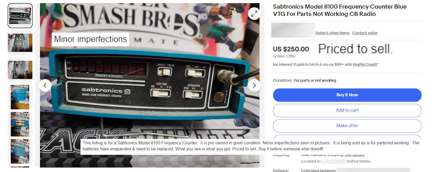
For some reason, a non-working device with a (hopefully intact) broken display cover, swollen batteries (and quite possibly corroded inside,) no battery cover, no (oddball) power adapter, and covered with dirt for $250 doesn’t inspire me to add “Priced to sell” in the description. Especially when the device has been superseded many times over with modern equipment at lower prices.
I tried to limit myself to things I could possibly use, and I (mostly) did so. We’ll see if all these things actually work, or if some of them need some work.
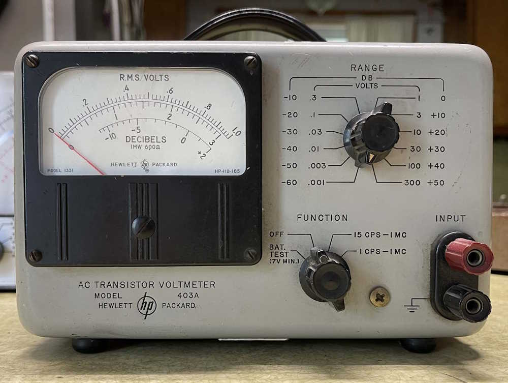
This HP AC Transistor Voltmeter Model 403A seems to be in good condition, and has a Westinghouse tag on the back. I can’t really test it because it has some odd battery requirements. It looks to need 5 mercury cell batteries - 2 4V batteries, and 3 1.35V batteries in a configuration that provides bias and + / - voltages. These are unobtainable, so a small supply may be in order if I actually want to use this thing.
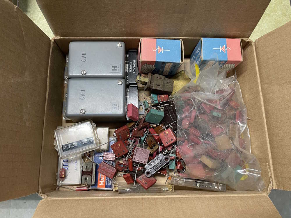
This came from a vendor that had boxes of parts. One part was $2, if you took the whole box it was $1. So…I took a box of mica capacitors and some other parts. High voltage mica caps can always come in handy.
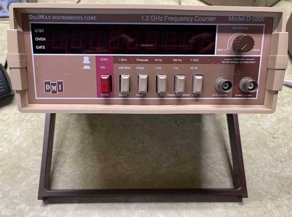
This DigiMax Instruments D-1200 counter claims to go to 1.2GHz, and has lamps for an ovenized reference on it. It’s awfully light, but it does light up. I need to get a signal in it to see if it’s actually counting, or if it’s just spitting out garbage.
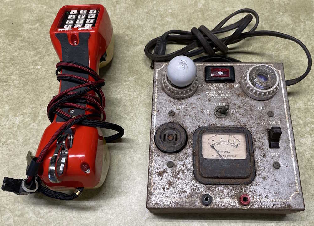
The Harris-Dracon butt sett was picked up becaue it was cool looking. I don’t know what I’ll use it for, but whatever. The Waage All-Purpose Tester Model 066 test box was a dollar - it’s mostly just an ammeter you can switch out, with a fuse and a lamp for testing the AC line. It’s pretty rusty, but looks clean inside. Who knows where this will end up.
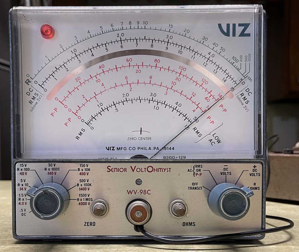
This VIZ Senior VoltOhmist WV-98C meter seems to be operational, and has a case you could kill a poodle with. It’s a two-tube unit, using a 6AL5 Dual Diode and a 12AU7 amplifier. It’s small enough to go on the bench instead of the giant EICO VTVM currently there.
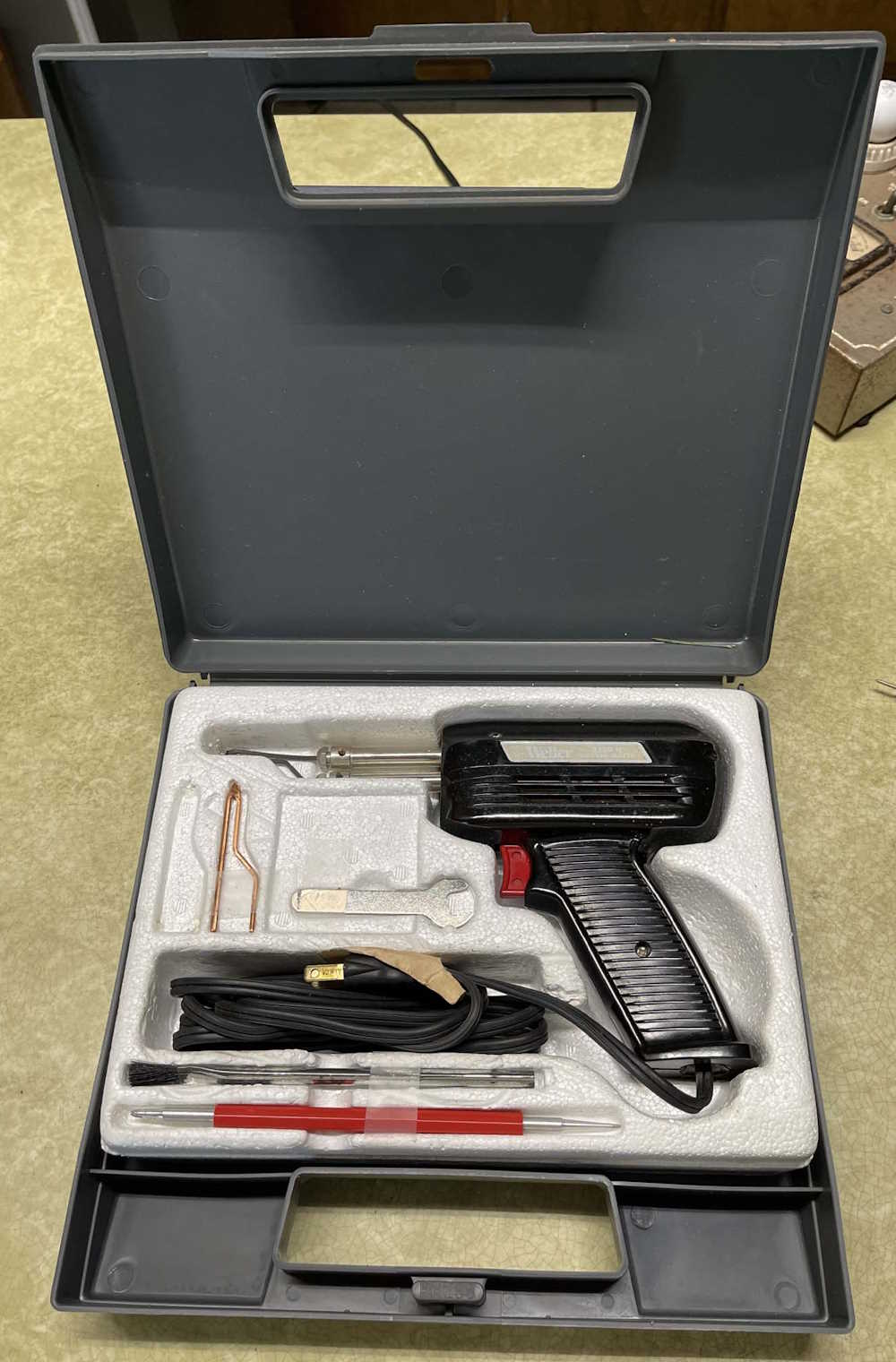
This Weller solder gun has all of the tools with it, and is one of the units made in the USA. I have a couple of these, they come in handy soldering chassis items.
That’s this year’s haul. I tried to limit myself to smaller items I could use, and I mostly succeeded. There were a lot of larger items that I wanted, but left there since I don’t have room for them. In all, I didn’t spend a lot and brought home some neat things.
Next show is either the Van Wert, OH show - that’s a long drive and may not be in the cards - and/or the Columbus, OH show which is a lot closer to me and much easier to attend. Either way, stay tuned for pictures from those shows, and I’ll see you there!
The VIZ and HP meters had some serious issues and became parts. The Waage 066 is now a lamp.
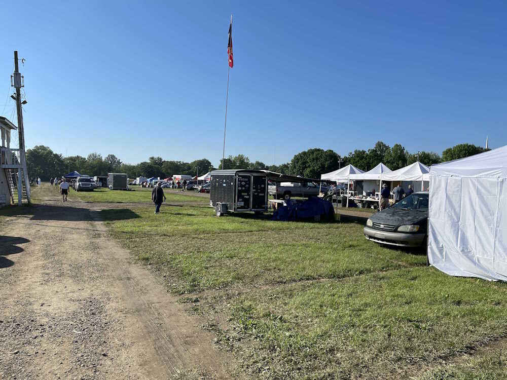
It was raining where I was, and threatened rain all the way to the show - but when we arrived, the sky had cleared and it was a sunny, slightly breezey 71F. Essentially, perfect conditions for wandering the aisles. While I didn’t see some of the things I hoped would show up this year, there was still quite a bit to look at. I spent a couple hours wandering the show before heading out for some lunch.
The usual mix of equipment showed up here, and a few things managed to wander home with me. This is what I saw at this year’s show:
I wonder if they will take my battery club card?
A BC-221AA Signal Generator.
A buck a box or two bucks per part. I took a box.
Motorola Communications Analyzers.
An old school engine analyzer.
Some equipment and schematic manuals.
This guy never prices stuff.
Don't bump the equipment stack.
The lighted switchbox up front was neat.
The VIZ meter in the middle went home with me.
An estate sale from a silent key.
Frequency doodads.
A floppy drive, and lots of solder.
A Boonton AM/FM Signal Generator.
A couple of neat chromed radios.
A Heath Weather Station with all the stuff.
An interesting Lafayette tuner on the right.
Something to monitor 3-phase stuff?
We go to shows for tables like this.
The 70s appear to be calling.
I swear one of these scopes exists for every person on the planet.
Yet another sig gen, this one branded Olson.
Some interesting rack mount radios.
More radios, who would have guessed?
Some Heath stuff.
I bet you can't guess what this is.
The scopes on the ground were free.
A big piece of Singer test equipment.
A bunch of GE radios.
A weird tape deck and some EQs.
A Tek 455 scope on it's cart.
A Tek 547 missing a plugin.
A bunch of odd testers. I took the one with the bulb.
Trans-Oceanics for parts.
A Knight radio and a tube tester, and stuff.
I don't know what this one is.
.
Next show will probably be the Columbus, OH hamfest, although there are some happening before that. Regardless, I’ll (maybe) see you there!
Sunday was a slim day - many of the vendors pack up Saturday evening, but maybe 1/5 were still on the grounds, not counting the exhibit buildings. Lots of reduced price deals and some free stuff were around today, and I still managed to bring home too much. Today’s lunch was Bourbon Chicken and a milkshake - a bottle of sauce managed to make it home as well. In all, this was a good show even if Friday was a bit messy. It’s also the first year I didn’t go through the exhibit halls, but there’ s nothing in there I needed this year.