Pretty much exactly what you’d expect. Nothing really exciting…
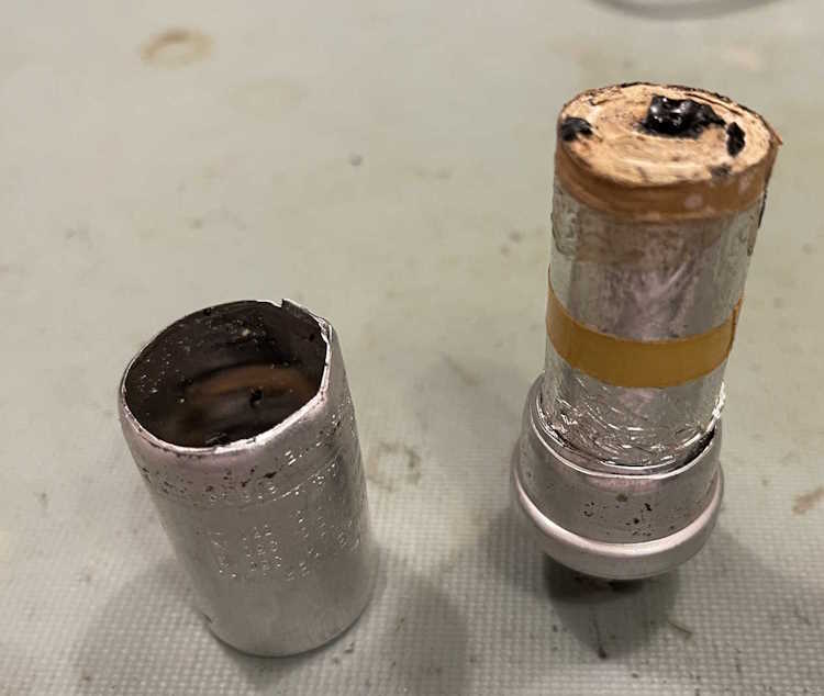
I decided to take the top off the capacitor removed from the Heathkit AF-1 that I’m working with, since it’s completely dead and as light as can be. There’s probably no wet electrolyte left in this thing at all.
My pipe cutter made short work of the aluminum can, and it separated into two pieces.
As expected, this thing was dry as a bone. It looks to have used some sort of tar or other dark potting material, which was also dry and hard.
The material itself was just paper and foil, wrapped with old tape. I assume that somewhere in there are dividers for for the different sections.
There’s not much else to be said about this device. I’m going to pull the old material out and keep the base for other things, but the device itself gets replaced on the AF-1’s chassis.
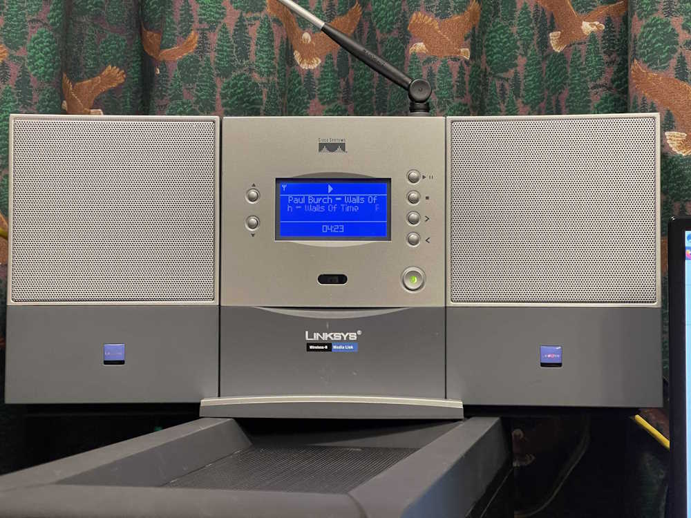
A few years ago, I wrote a piece detailing some fun I had with a Hamvention find, an ancient Linksys WML11B media player. You can find that article right here.
This is a device from the very beginnings of the Consumer Internet Age, and is evidenced by it’s early Wireless-B connectivity. Fortunately, it also offers an Ethernet connection. But…that’s about it. Modern browsers refuse to communicate properly with this thing’s web interface, seeing as how it was designed to be used with IE6. Modern HTTPS audio streams don’t work here because HTTPS was just starting to show up in the consumer space when this was made.
The weirdest thing is that a gigabit Ethernet port, which is usually more than capable of negotiating downward, doesn’t work well with this device. The device will simply stop playing and claim it has no connection after a short period, usually around an hour. A 100base connection will play for hours until the relatively fragile buffering in this device hits a hiccup and it stops.
That’s a real shame too, because this is actually a pretty good sounding device, probably on par with the Squeezebox Boom that came much later. While this device did have a now long-gone backend that would feed it station lists, it also had it’s own internal presets. You could use this thing and not have to worry about someone pulling a Reciva on you.
Seeing as how those squeezebox devices are still viable due to the continuation of the media server by Lyrion, I’ve decided to replace this unit with a used Squeezebox Radio that I purchased online for cheap. I’m not sure what to do with it, but the amplified speakers could be useful since they’re of decent size and good sound quality.
Since this device came to me with a bad power supply, the first thing I want to do is get that supply back into operation so I can do some further tests on the device. It’s a relatively simple affair, consisting of the transformer, rectifier, filter, and a somewhat unusual voltage regulator tube. There’s nothing going on here you haven’t seen before save maybe the VR150, so let’s jump right in.
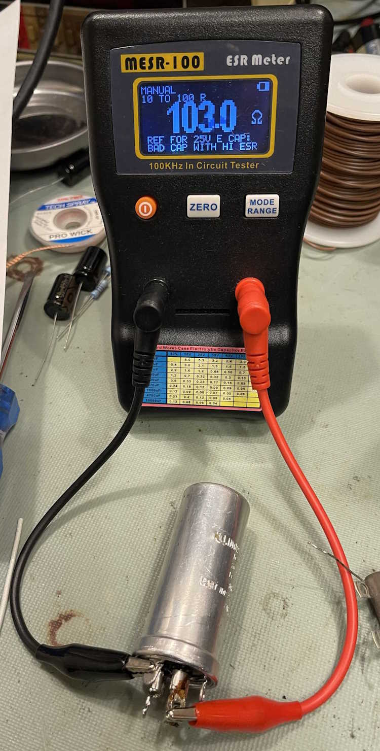
The whole reason for this initial exercise, is the original capacitor being bad. The can feels like it has nothing in it at all, and 103Ω certainly isn’t good for an electrolytic capacitor!
The new parts went in to the bottom of the chassis without issues except for the leads being shorter on a few.
Spaghetti comes in handy and is used liberally here.
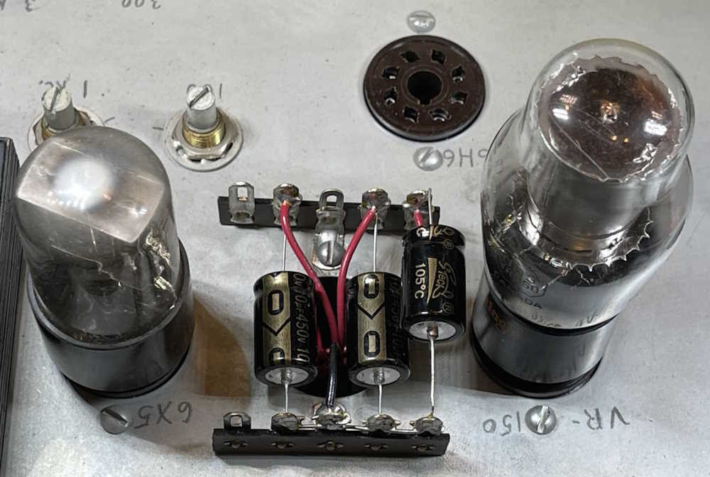
The top looks a bit different now:
I’m not really concerned with the one capacitor being close to the VR150, it’s a cold cathode tube and doesn’t make a lot of heat. The one close to the 6X5 rectifier may need a heat shield for longer life, however. I think it’s far enough away, but you never know.
A new power cord was added, but I want to check my work before applying power and it wasn’t plugged in yet. That’s coming in the next part, as is some testing with new potentiometers. Stay tuned!
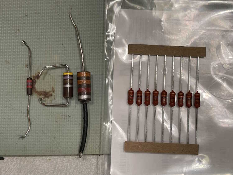
One last thing is the size difference between old and new parts. Here’s some new 3.3k 2W resistors replacing the one next to it. The new ones are almost the same size as the old 1/2W parts, and certainly smaller than the 1W and 2W parts shown. It’s amazing how technology has changed our ability to pack more into a smaller space.
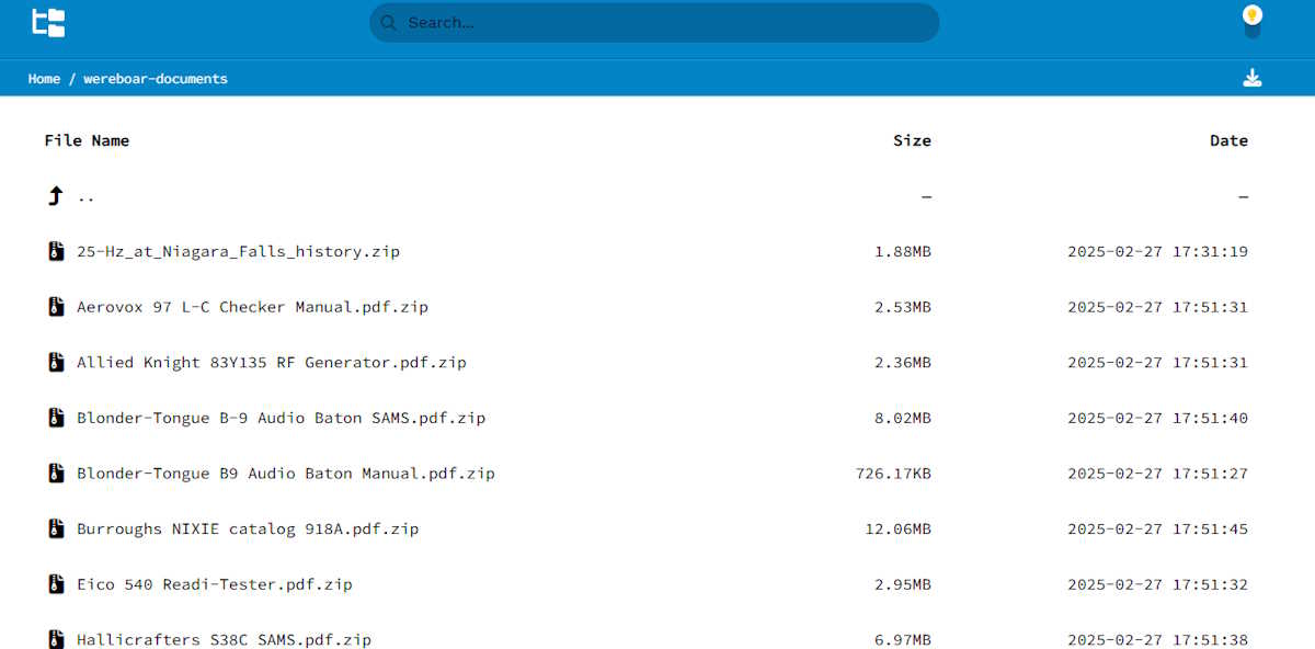
I’ve wanted to create an on-site documents library for some time, but just never dug into a simple web-facing file browser. Well, I just found Directory Lister, and it does exactly what I need. it presents all of the files with no fuss, no uploads, and no login needed - just pick what you want and download.
In order to save a little space, and prevent your browser from trying to open the file instead of downloading it, I’ve zipped up everything. If I can, schematics and documents of what I work on are all posted within this library. Check it out here: https://wereboar.com … r=wereboar-documents.
If you want a copy of everything in the archive, you can get that here: https://app.box.com/ … ide0trkeb0wi4j6nta20. This URL will change as I upload more documents and archive them, but I’ll try to keep at least two older versions available. I’ll post any new updates to the collected archive when they’re available.
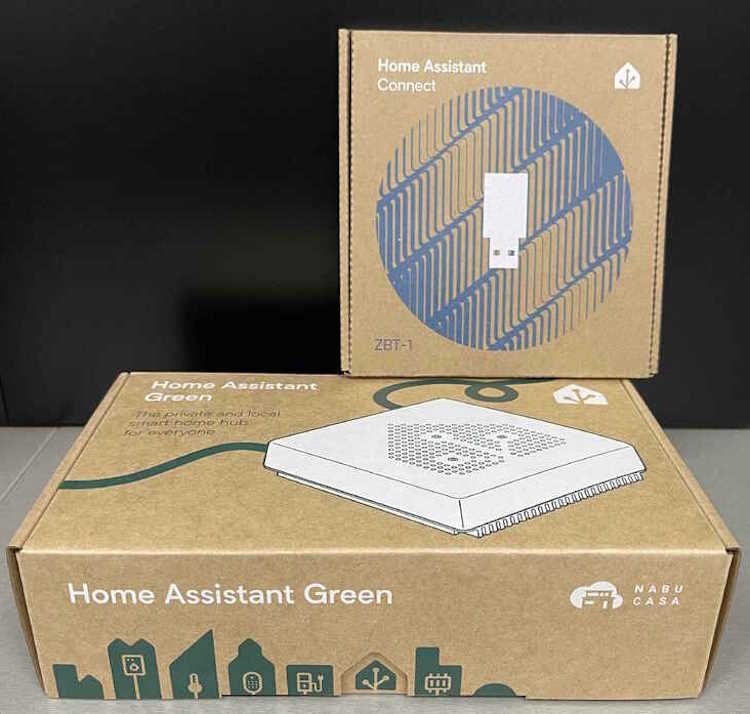
Recently, I decided to give Home Assistant another try. I had have given it a go in the past, but at the time it simply didn’t give me enough functionality to be “worth it.” Now, with the proliferation of cheap zigbee and LoRA sensors, I decided to see what it can offer.
To facilitate this, I purchased an official Home Assistant Green CPU with the official ZigBee dongle. Why? Well, here’s what the website says:
Ready. Set. Go. — The affordable Home Assistant Green is the easiest way you can start using Home Assistant. It’s plug-and-play and comes with Home Assistant already installed.
Here it is on the site itself, as of February 26 2025:
All cool, right? Remember that it’s already installed.
So, I order from a company that I’ve dealt with before, and a week later it shows up on my desk at work.
I read the little booklet inside the box. It apparently has to be connected to the internet in order to work the first time. Why? Well, remember that little bit about the OS and system being already installed?
It’s not.
It has to download an install it from github. So the very first thing I encounter is that it’s not actually like it is on the website. It, in fact, is not already installed on the device. It simply has some sort of bootloader stub that captures the image and installs it. No indication from where, no indication of how long it might take, nothing. The lack of information here is disturbing.
I plug it in, apply power, and walk away to make something for dinner. A while later, I come back and hit the indicated webpage on the device, and all I get is a big screen telling me that the system failed to install. There’s a log, which I grab and copy here: https://pastebin.com/gdYK38d6
I comb forums, make posts, contact the vendor. The vendor is very responsive, but can’t really offer anything except that they’ll take it back and try to flash it themselves. I get no reply from forum posts, but there are plenty of other people who have the same issue. The creator of the Home Assistant system only indicates that I don’t have an internet connection.
I wonder how the software downloaded and tried to install. Must be that wireless wire I hear about?
Anyway, after spending the better part of half my day on this thing, I set it aside.
Something occurs to me. It says look closely at the log. And there it is:
[supervisor.dbus.timedate] No timedate support on the host. Time/Date functions have been disabled.
[supervisor.host.services] Updating service information
[supervisor.host.sound] Updating PulseAudio information
[supervisor.host.sound] Can’t update PulseAudio data: Failed to connect to pulseaudio server
[supervisor.host.network] Updating local network information
[supervisor.host.apparmor] Loading AppArmor Profiles: {’hassio-supervisor’}
[supervisor.utils.whoami] Whoami service failed with SSL verification: Cannot connect to host services.home-assistant.io:443 ssl:True [SSLCertVerificationError: (1, ‘[SSL: CERTIFICATE_VERIFY_FAILED] certificate verify failed: certificate is not yet valid (_ssl.c:1000)’)]
[supervisor.core] Whoami service SSL error
[supervisor.core] System time/date shift over more than 3 days found!
[supervisor.host.control] Setting new host datetime: 2025-02-21T17:58:06+00:00
[supervisor.core] Fatal error happening on load Task : Automatic time synchronization is enabled
[supervisor.docker.monitor] Started docker events monitor
[supervisor.jobs] ‘Updater.fetch_data’ blocked from execution, no supervisor internet connection
Pay attention to the things about time, then go down to the part in the middle about certificate verifications. The SSL cert onboard is in the future. That tells me the time onboard is wrong, in the past, and probably whatever the hardware gave the Home Assistant install process! Only then does it check the time, and yeah - it’s way off. After that, it’s all failures because the SSL checks failed. Of course the supervisor doesn’t have an internet connection, it’s certificate is invalid because the device didn’t check the time.
Why didn’t the Home Assistant install process check the time first thing, instead of in the middle of the process? I don’t get that at all.
There’s a reset procedure. It wipes the drive. I try that. No luck, now I don’t even get the failed install web page. I try it a couple of times, no luck. Forum posts suggest seeing what’s on the screen, so I connect a monitor to the device and find that it’s sitting at “Waiting for Home Assistant CLI to be ready.” It never “becomes ready” so it dumps me into an emergency console which doesn’t really give me much power.
I do notice that there’s a message about the wipe process failed in the boot messages. Hmm…
There’s a “You can flash this with an SD card” procedure. I try a couple of different SD cards with several different flashing tools. None of them work. It just tries to boot normally.
I’m at a loss, and running out of patience. The vendor has agreed to take it back. I set it aside and sleep on it.
So why didn’t this thing get the time from the network. Is it trying to get it from my router instead of outside the network? That can be an issue. I run a Mikrotik router with RouterOS6. It doesn’t offer the time by default because Mikrotik’s philosophy was that your router isn’t a clock. You can’t depend on the router being correct. You want a clock, get a clock. It does have an internal SNTP package, but that wasn’t really doing much because I didn’t care. The router routes packets - it doesn’t care if it’s 2011, 2025, or 2100. It just routes packets.
Mikrotik does offer a NTP package that can serve time to the local network. I install that, set it up, and verify with “ntpdate -q 192.168.1.1” that I’m getting a response. Ok.
I try to boot again. Nothing. Reset - still giving me the can’t wipe error. SD card flash, nothing. I notice some jumpers on the board itself, and decide to go for broke and open the case. I’m sure the warranty is now void, but it’s going to be void when I hit it with a crowbar. But, I digress - there is indeed some headers, one has a jumper, and it’s marked “NOR / REC” and is in the “NOR” position.
Normal and Recovery? There’s no information about it. I move to “REC,” apply power, and…
I see the machine downloading the OS and installing. All of the error messages about kernel time synch that were there are gone, indicating that it indeed was trying to get the time from somewhere. It installs, powers down. I put the jumper back into the “NOR” position and boot. And there we are, the Home Assistant setup and login appears.
I put it back together, let the vendor know, and write a WTF Man? letter to the creator of Home Assistant, a company called Nabu Casa. It seems to be working just fine.
So WTF Man?
When I emailed Nabu Casa originally, the only thing they said was “You don’t have an internet connection,” completely ignoring the fact that I indeed had an internet connection because the software downloaded and tried to install. That was worthless. When I was done, I emailed them and told them what fixed it - no response so far, nor do I expect one because, while I wasn’t necessarily impolite, I wasn’t holding back either.
To me, it looks like this device expects your router to provide a correct time. If it does not, or does not provide the time at all, it fails silently and even the manufacturer doesn’t know this. They simply assume that your device is their device and all devices act the same. Forum posts that had this same problem were solved by taking the Green unit somewhere else and trying again - it works, probably because they now had the right time. Others indicate they had to mess with DNS setting in their router - was that the fix or did changing those (and the subsequent restart) simply force the router to properly update the time? Probably yes, a little of that and a lot more of this.
The vendor, while extremely responsive, wasn’t a software troubleshooter and could only offer me help with the hardware. They could attempt flash or give me a new one.
So the TL;DR here is make sure your router can provide the correct time, otherwise - you’re in a world of hurt!
But one last thing here - why didn’t the reset process complete, and why couldn’t it wipe the drive? (This may also be related to the flash failure.) It seems, from the posts I’ve read, that if something fails and the drive doesn’t get into the exact expected state, the wipe process doesn’t know what to do and fails. That’s extremely fragile, and I don’t understand why it does that. I will assume that it’s only wiping the portions of the OS that contain the Home Assistant containers, and if they aren’t there (in some cases I’ve read where the drive name being wrong causes this!) it just fails. It doesn’t stop, it just continues to boot and destroy itself more. Same with the failed install process - it just keeps going and destroys itself.
My advice to Home Assistant?
The time is obviously very important, since you’re using self-signed and served SSL certs. CHECK THE TIME BEFORE STARTING THE INSTALL PROCESS - If it’s before 2025, STOP. The system does not have the correct time. Or, check to see that it’s within the range your certs are good for, you’re providing them so you know the dates!
If it gets into the SSL process and one of the SSL checks fails, STOP. Since this is important to the supervisor that runs Home Assistant, continuing will only cause problems.
You need to explain what’s going on better, how long you expect things to take, and what that jumper is for inside the case. You need to explain certain things like it’s not installed, and that you need the correct time on your router before continuing.
Last, the install process is way too fragile. This is a consumer device, if you’re not able to recover from a simple bad install without using unpublished information you’re doing it wrong.
Final thoughts
If you’re planning on getting one of these for yourself, do yourself a favor and make sure you have a good, wired internet connection and your router can provide the correct time.
In the last rebuild I did, I simply removed everything that was going to be replaced, and replaced it. See this post for details on that project.
This time, however, I think I’m going to attack the problem from a different direction. This unit has some interesting modifications that directly affect how the unit measures things - those being the replacement of some of the 200Ω rheostats with 5kΩ potentiometers. I’m not sure why, but with a dead power supply there’s no way I can test it.
The logical step would be to fix the power supply first, do some experimentation, and then rebuild the rest with the knowledge gained from those experiments. That’s what I’m going to do.
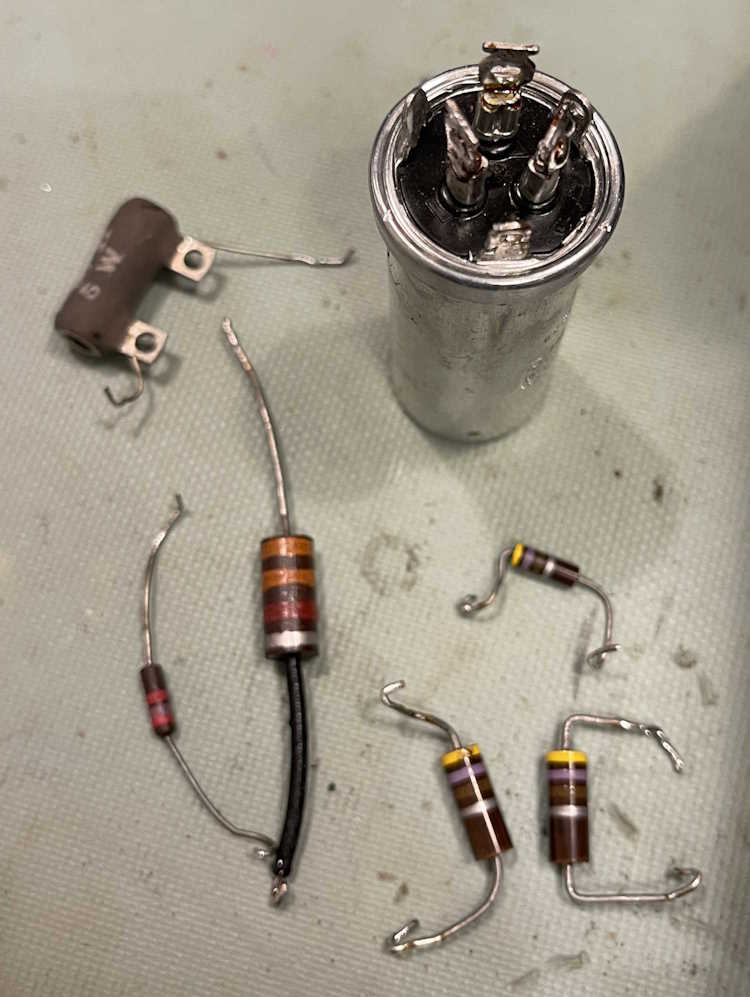
I originally was going to use some parts I had on hand, but (other than the filter capacitors) decided just to go ahead and get some new, low (compared to the old stuff!) PPM parts. As I needed a couple of other items, I just went ahead and ordered the whole batch from Mouser.
First round is going to see these parts replaced:
3x 10μF capacitors, at least 350WVDC (already have these)
3x 470Ω 1W resistors
1x 2.5kΩ 5W power resistor
1x 2.7kΩ 1W resistor
1x 3.3kΩ 2W resistor
For economy of scale, if there’s a part that’s a 1/2W and I’m buying multiple 1W parts, the lower value will get the higher value wattage. This allows me to get more of a given part, get a price break, and some extras for my parts bin. The 2.7k and 3.3k aren’t really part of the actual power supply, but these provide voltage to the remaining circuits. I’m going to go ahead and do them this round.
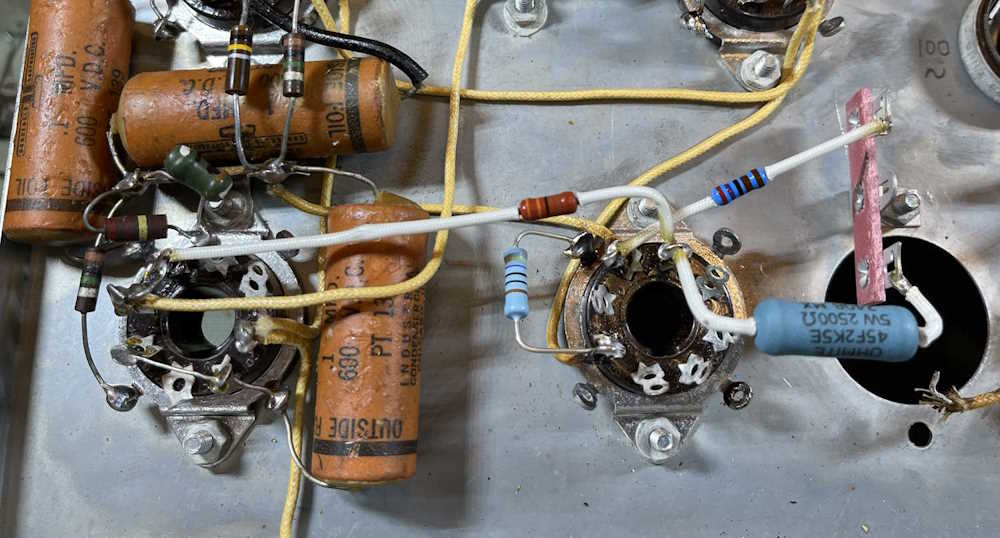
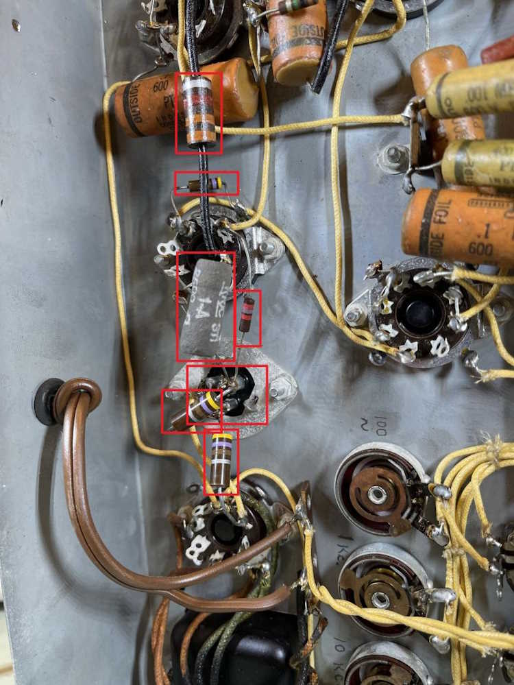
The parts being replaced are outlined in red:
The only issue I can see is how to mount the capacitors. I’m not worried about looks, so the can goes - I just need to decide how to mount the new parts.
I should have the components later this week, part 6 involving the power supply is coming soon.
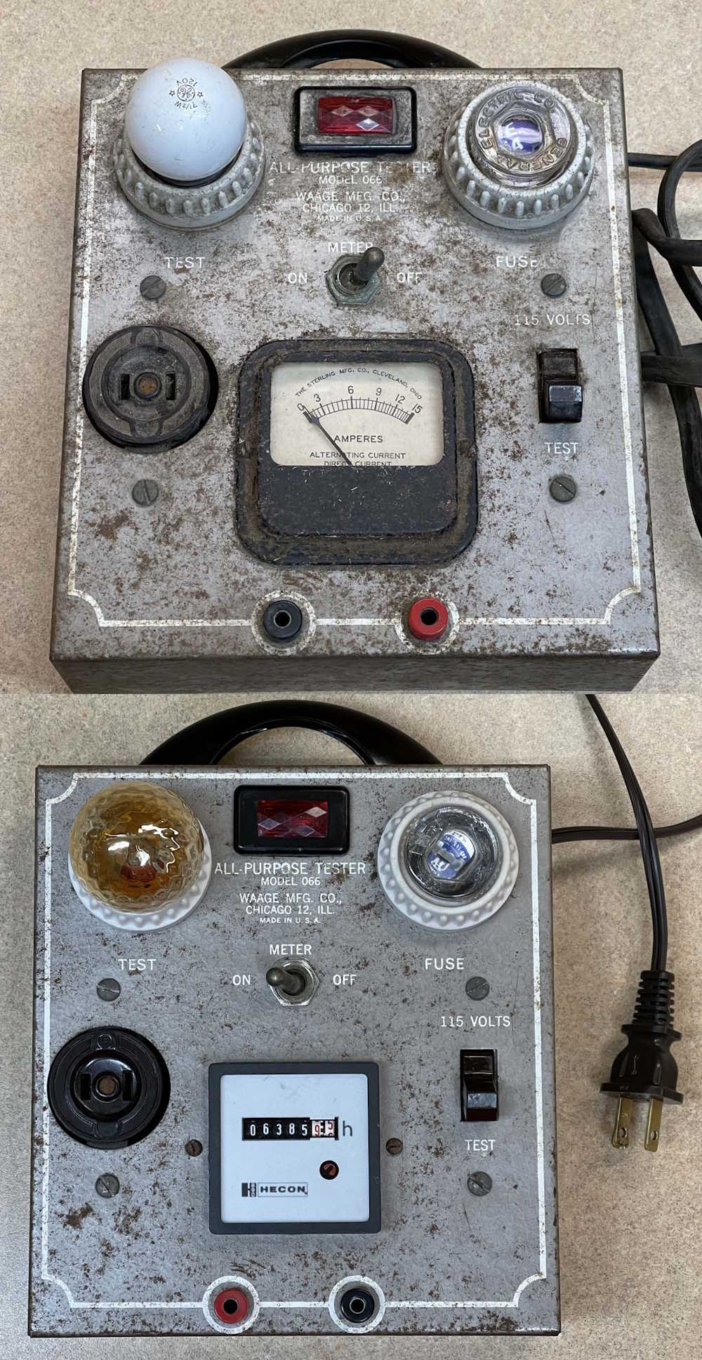
Instead of discarding it, I decided to open it up, remove all of the wildly underrated wire, and make it into a display piece.
Everything was removed, cleaned and replaced save the original ammeter. A 15A meter isn’t all that useful here, and I didn’t have anything that would fit the hole except for an hour counter, so it went in there. I’m going to look for a voltmeter at shows this year, but a 2” meter isn’t as common at 2 1/8 and larger units.
The outlet, big toggle, and sockets were all cleaned in an ultrasonic bath. The little metal toggle in the middle, certainly not rated for 15A, was just surface cleaned. All parts were reinstalled into their original location. A new power cord was added None of the switches or outlets were reconnected - they’re just decoration at this point.
A bit of cleanup of the surface rust, an LED peanut bulb, and we’re back in business.
I know some said to restore it to use, but…it’s not really worth doing that. It’s now sitting in a room in the house I don’t use much, providing just enough light to see what’s in there.
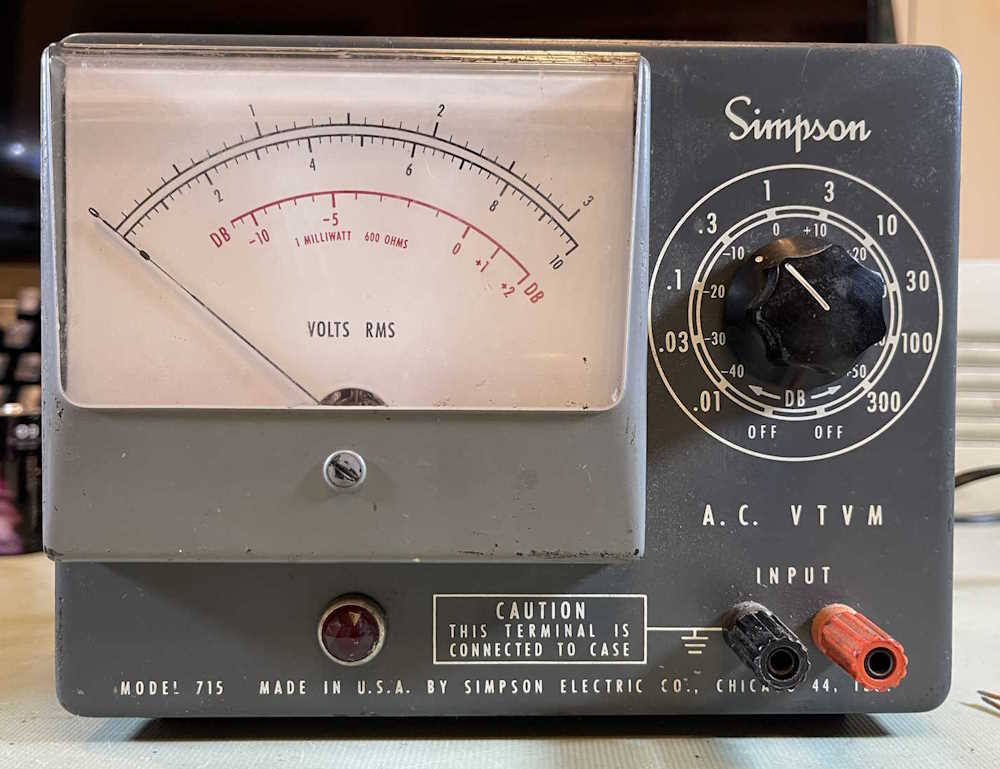
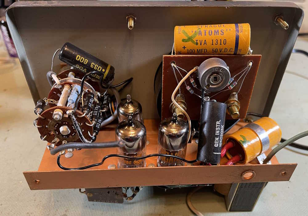
This device is an AC only VTVM with a dB scale. It’s often mentioned as a meter made for audio use. It’s a compact, good looking unit.
The front is mostly taken up by the meter face:
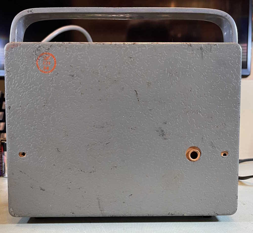
The back has nothing except the screw holes and a metal grommet hole for the cord.
When I received this meter, it had a rubberized 3-prong grounded plug on it. I’ve seen pictures of others with 2-prong, but the schematic seems to indicate the chassis was grounded. I’ve got a two-prong on it for testing, but will replace with the proper cord later.
The inside of the unit is pretty busy.
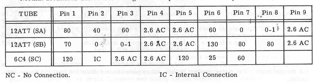
Tube compliment is:
12AT7
12AT7
6C4
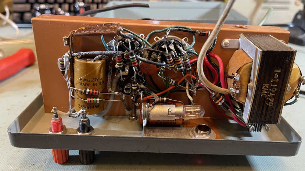
Power is provided by a selenium rectifier for the transformer. It’s a pretty simple device, an input amplifier to provide the high impedance, a cascode amplifier to drive things, and the signal voltage is rectified right on the meter. Nothing too fancy here.
However, like many things from this time period, it doesn’t work right. That’s probably due to the capacitors leaking, or perhaps something else has gone wrong over the years. The Simpson manual provides a schematic, but no real troubleshooting information.
What would be helpful here is voltage information for the tubes and some “Does it do this?” information.
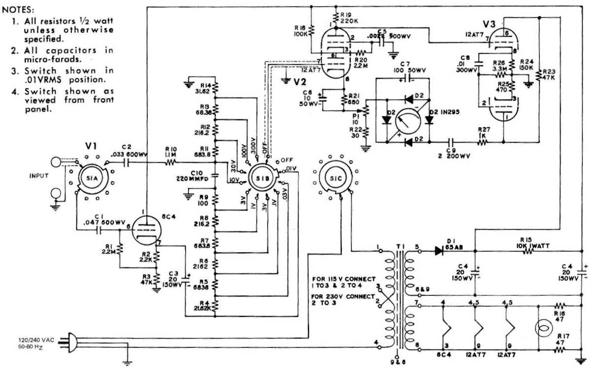
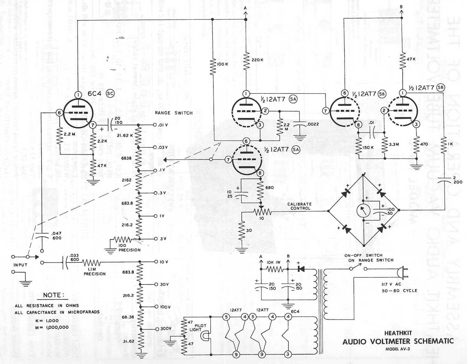
Enter the Heathkit AV-3.
There’s no picture, you can find plenty of them all over the internet. However, what’s odd about this unit is that some of them have “Simpson Elec Co” on the meter face. Why is that? Well, here’s the schematic for the AV-3:
You’ll notice, other than parts placement on the schematic, that it’s the same thing. Heathkit must have contracted Simpson to assemble these for people who wanted to purchase an assembled unit. Since this was also sold as a kit, that means one of Heathkit’s lovely manuals must exist for the unit. BAMA and other souces didn’t have it, so I sourced one from ManualMan, and there it is:
This thing may have a chance at living again. Stay tuned!
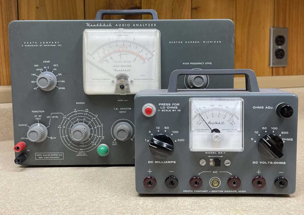
Here’s a picture of the EK-1 next to it’s big brother, the AA-1:
Isn’t that adorable? It’s so small.
The EK-1 was a piece of equipment you build as a teaching aid for an electronics course of the same name. It’s interesting in that it’s a voltmeter/ammeter with no battery requirements - although the ohms function does require a single C-cell. The Ω/V rating is pretty low, since it’s really nothing more than a meter with some resistors in it - no active components here! The only AC function is a neon lamp to check 110VAC, so this is a glorified appliance test box.
Still, it’s cool in that it looks like a piece of Heathkit equipment, there’s no batteries needed for the most part, and it can sit there on the bench ready to go as a power supply test unit, or a tester for anything else where a bit of load won’t bother it.
It’s going to go on the bench as soon as I give it a contact cleaning and a new battery. (The AA-1 is also in queue.) You’ll probably see it in some shots in the future, stay tuned!