A Heathkit IM-104 Multimeter - An interesting teardown and cleaning.
Tuesday, April 21, 2026 at 08:29:52
I picked this device up at the Cuyahoga Falls Hamfest this year. In my quest to not bring home any more metering equipment, I brought home only three this year - a Keithly microvolt meter, a generic Heathkit tube device, and this one. I’m not sure, but this is probably one of - if not the first - of Heath’s FET driven meters.
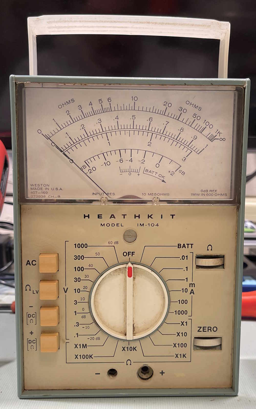
It was sold as not working. Well…these had a tendency to lose the FET in the front end, so…yeah. We’ll get there.
What’s so special about this? A VTVM presents a high-impedance load to a circuit. That is, there’s very little load from the meter itself so you don’t disturb your circuit. Meters like the Simpson 260, on the other hand, simply drive the meter movement from your measured voltage. This presents a lot of load, and can change the value of measurements in a circuit with small signals. The FET meter attempts to rectify both of the previous devices by presenting a high impedance AND a low current requirement, giving you a portable instrument that does the same thing a current-hungry VTVM does.
However, none of that matters if it doesn’t work. Let’s check it out:
The back comes off in a fiddly manner, you unscrew a big screw and kind of lift the bottom of the back while attempting to pull the back towards you and slide it out of it’s slots. This has the effect of needing 3 1/2 hands, but eventually I removed the back. Inside is compact:
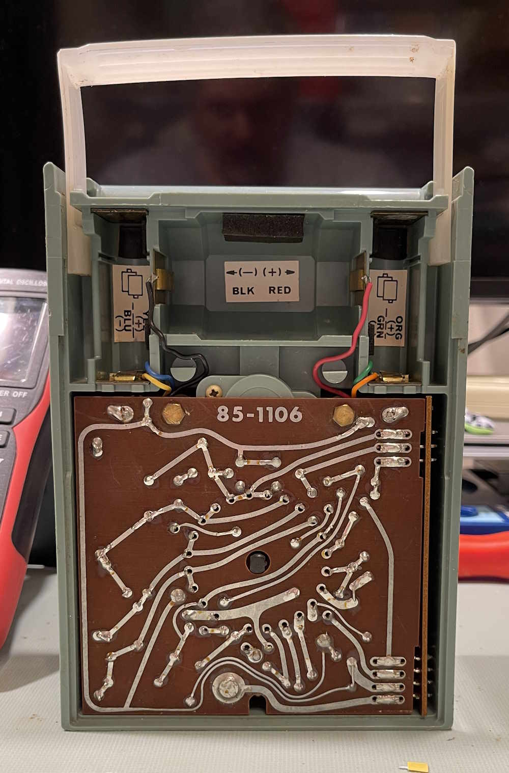
I can immediately see there are multiple layers in here. It feels firmly held in…by something. But first, the batteries. This thing needs 1 D cell for the ohms, and 4 AA cells for the measurement circuit. It’s run in a split configuration to drive an op-amp, so you have +3 / -3 VDC. The battery contacts are somwhat corroded, however.

Fortunately, it had carbon-zinc cells. These cause localized damage that can easily be removed with some scotchbrite and cleaner. This type of damage can cause rust to steel parts when it’s in contact with them, but is usually just where the battery is. This is unlike alkaline (and old mercury) which will outgas and cause everything to turn a shade of green before turning a shade of “open wires.”
Install some batteries, and…nothing happens. Chances are it’s a very dirty switch, but let’s get it apart and check that FET.
How do you get this thing open? Well, that’s an adventure in itself. I’d suggest grabbing the manual and reading it, because there’s some involved steps to dismounting the board. You can grab a copy from my documents library, or from WR5KL, who graciously hosts it. Links are at the bottom of the page.
Since it’s a pain to get open, I’m not going to cover that. Read the manual. I will say that I got it apart a different (wrong) way, so it’s somewhat robust. Somewhat. Just do not try and pull the knob off. It does not come off, and does not impede the assembly of the unit.
The Heathkit IM-104 Assembly
Once the unit is apart, we have the main assembly. There are three boards, a top board with the active components, a lower board with some passives, and a side function assembly. This pulls apart easily.
Remove the side function assembly by working it off. It’s connected with 4 sets of prongs that go into mating connectors on the side of the boards. Essentially, this is one of those big amphenol pinned connectors without the white housing. Set that aside.

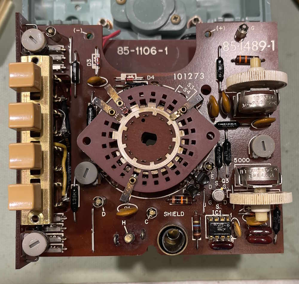
The main assembly consists of two boards. The top has two range switch layers, and all of the active components. The FET, a special dual instrumentation device, is the metal can in the lower right corner, just above an IC. The IC is an old Motorola part, and is generally the equivalent of an LM301. The rest is some glue and passives to drive the assembly. The zero and ohms pots also live here.
This lifts off of 5 brass pegs that go through the board.
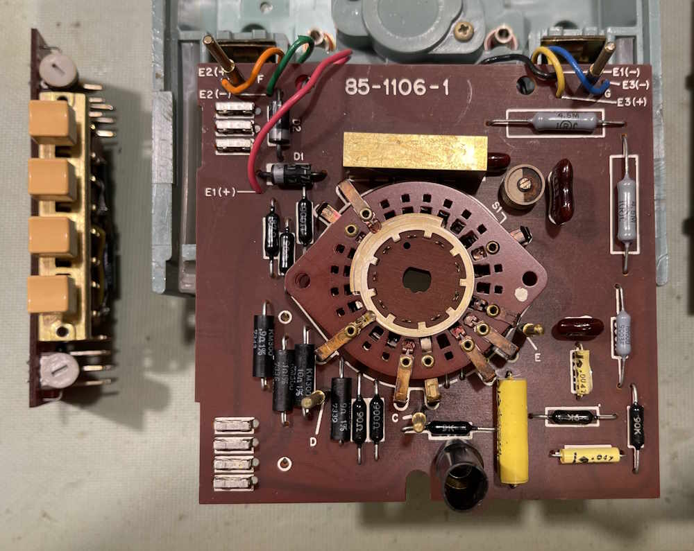
The bottom consists of two more range switch layers, and a bunch of passives for the ranges.
All of the range switch wafers float freely, and are chained together with a ridge on the center post. Remember that when reassembling, you’ll need to manually align the wafers to have it slide on, unless you’re lucky enough that the post pulled out with the removal.
How about that FET?
This is a single sided board, and the part was easy to remove and check. I was able to desolder quickly with braid and put the FET in my M-Tester. It’s good.
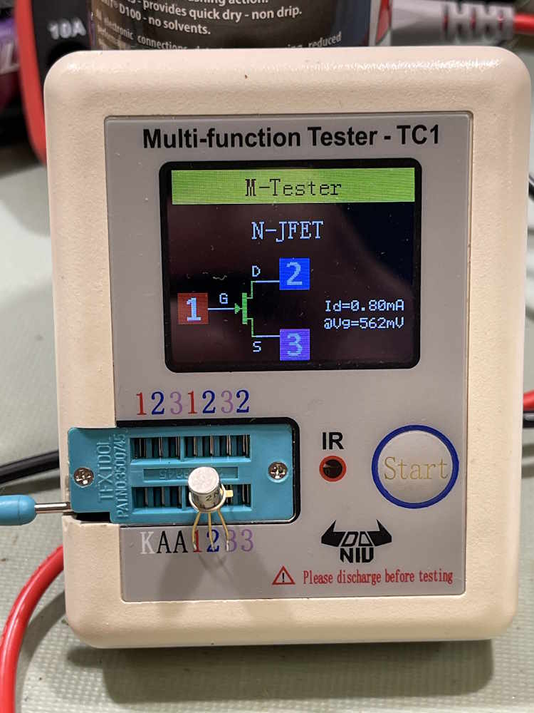
Both sides of the device measured as a FET. It got soldered back in. That means the range switch is probably just so dirty it’s not making contact. I was able to clean the tops of each layer and spray the bottom. That got us back to some semblance of operation:
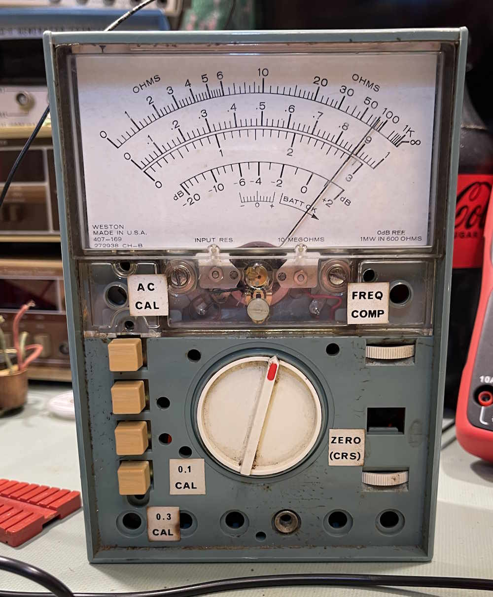
The switch is still very touchy, however. I decide to liberally dose the switches with Deoxit and let it set for a while.
A week later, and it’s working.
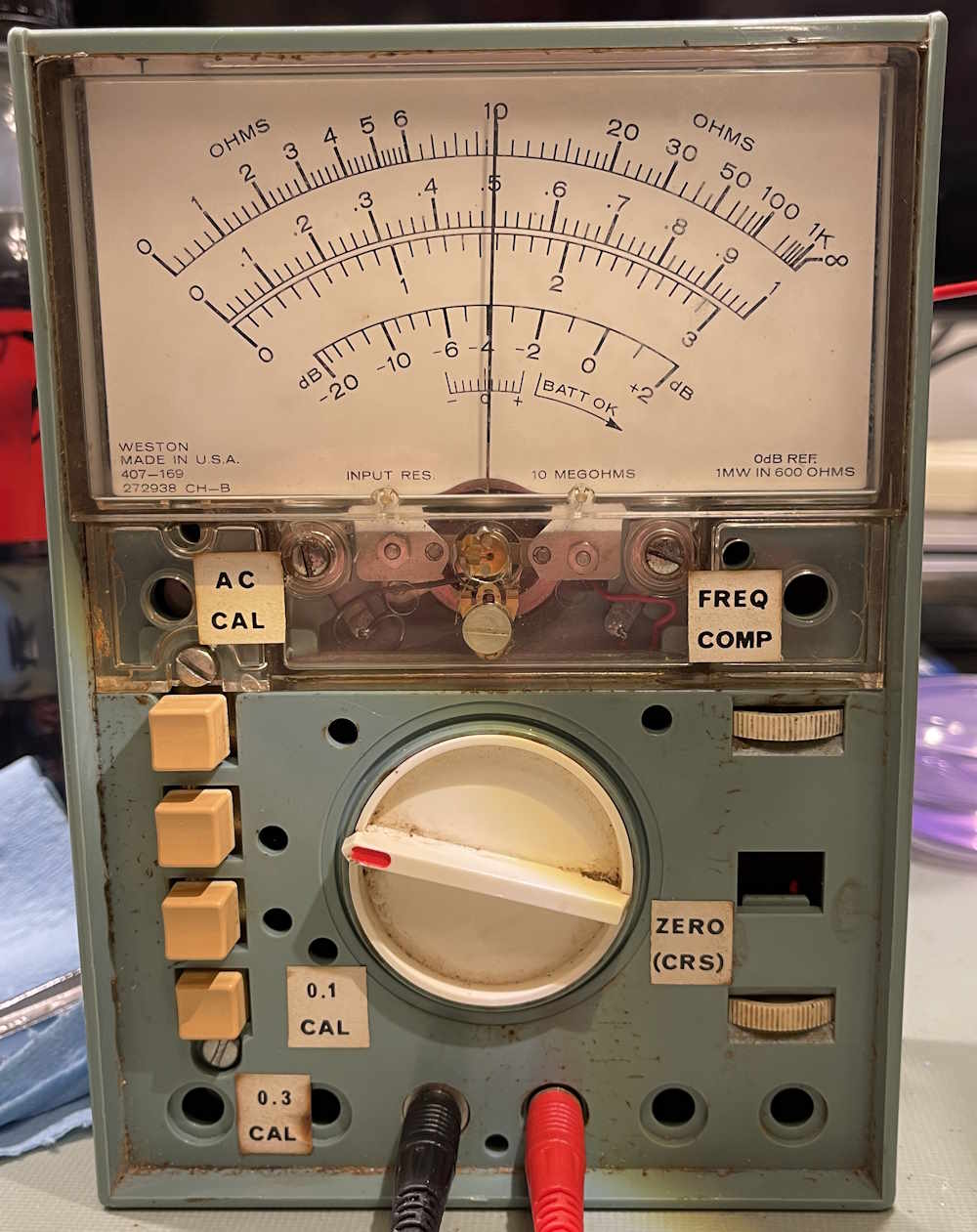
The switch is no longer touchy, and the meter is decently accurate. Alright! It’s still going to need a good cleaning of all wafers, but I can order some thin, flat swabs for that. Later, of course.
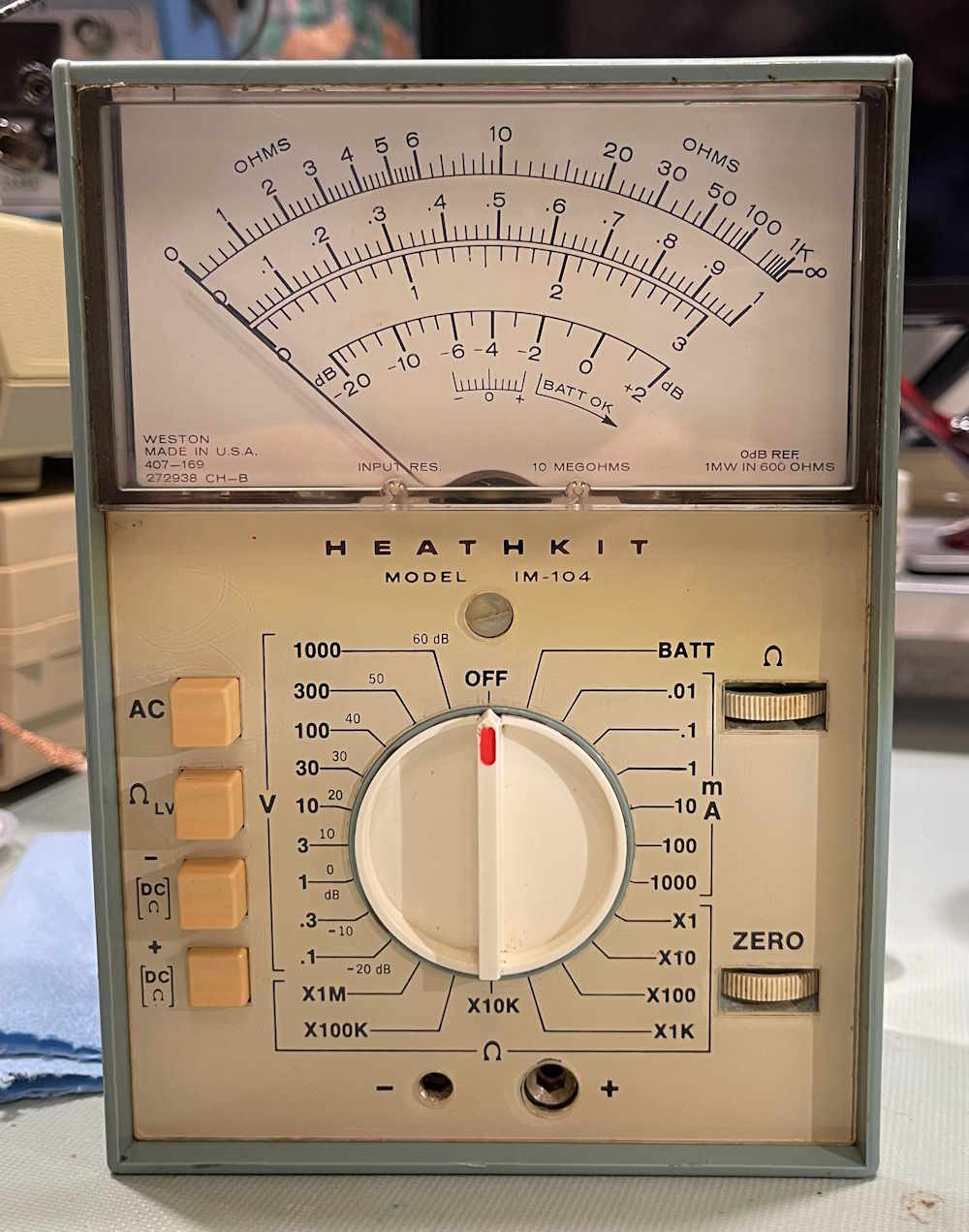
Some removal of dirt, and reassembly. It’s a nice looking piece with that weird instrument blue and those UV colored switches. In all, a pretty good purchase for the few bucks it cost.
I’ll probably do a complete cleaning on this later. Stay tuned:
Next part of this series: Coming sometime.
References
The Heathkit IM-104 manual on Wereboar Documents (from W5RKL’s site): https://wereboar.com … bly%20Manual.pdf.zip
This is a PDF, zipped up to save a little space.
The Heathkit IM-104 manual on W5RKL.com: https://w5rkl.com/wp … -Assembly-Manual.pdf
This opens (or saves, depending on your settings) as a direct PDF.