An Eico 145 Signal Tracer - Part 6d - Almost there!
Wednesday, October 16, 2024 at 12:30:07
Last night, I did the filaments, AC line, and the rest of the components, since I had enough (new) wire sleeve to coat them all. A valiant 330Ω resistor gave it’s leads for the capacitors feeding down from the volume control, and I replaced the 510k with a fresh resistor because I didn’t like the way the one I placed looked.
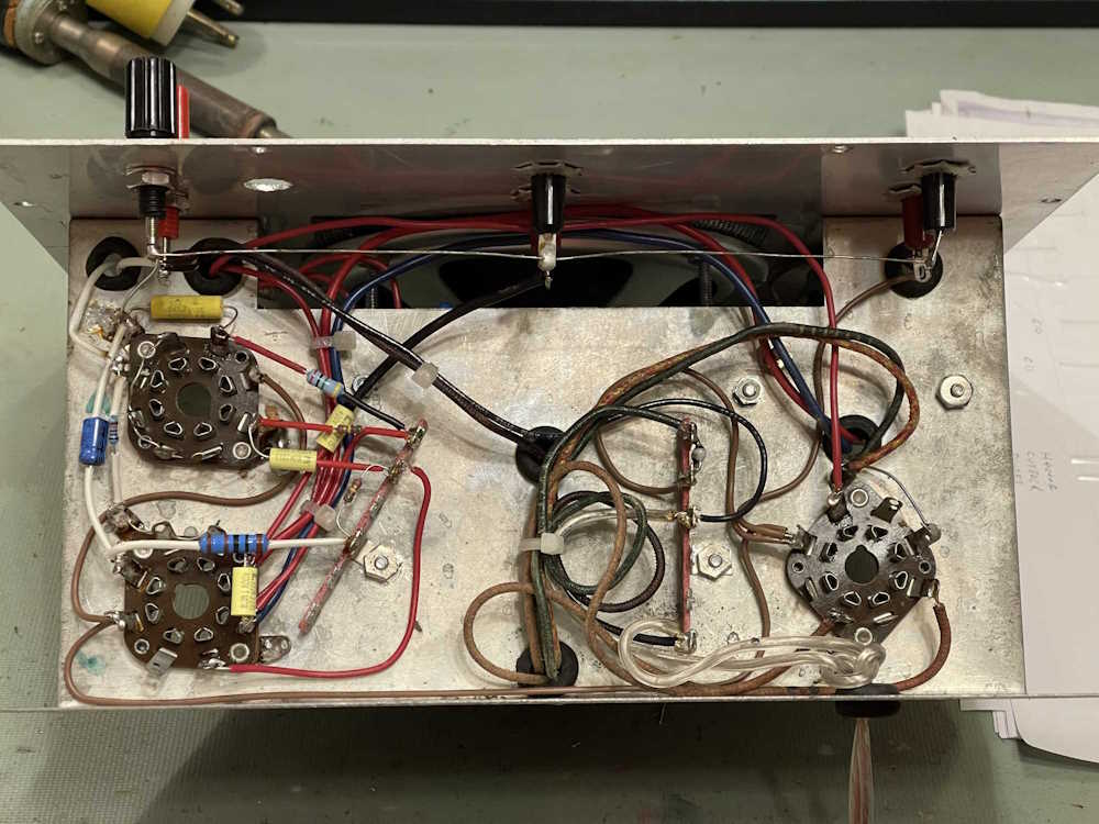
I’m still not totally happy with the way some of the components lay, but they’re all solid. I need to touch up some of the joints, but some look worse than they are because of the flux. I’m not worried about that.
The switch needs to be wired in, and there’s a few joints to touch up and solder in. The switch shouldn’t take that long to finish up.
There’s a little more to do, and then it’s “Check your work!” After that, I’ll bring it up with just the power supply to check voltages. Assuming all is good - we’ll have sound.
Stay tuned for part 6e, 7 and 8, which should finish this series. I’ll have a “my thoughts” at the end of the series as well, hopefully with some things I’ve learned about the process and what not to do.
Next part of this series: https://wereboar.com … the-rebuild-is-done/
Previous part of this series: https://wereboar.com … -to-run-a-few-wires/
Wrapup and link to all posts: https://wereboar.com … -and-final-thoughts/