ESR Testing with the FNIRSI LC1020E and the EICO 150.
Friday, April 24, 2026 at 05:31:41
I’ve recently had to field some questions in regards to in-circuit testing of ESR. While it is true that you can’t get a 100% perfect answer while the part is in circuit, you can get a pretty good answer about the quality of the part you’re testing.
Let’s take this EICO 150 Signal Tracer. This unit works, but has very low output level. Chances are, capacitors are bad and I’ve already verified that in the observations post, which you can read at this link.
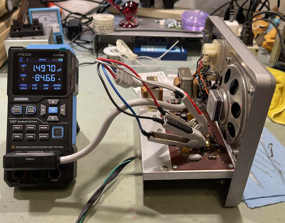
Let’s take the board of this device:

There’s a lot of little capacitors everywhere. Checking one of them with the FNIRSI LC1020E reveals a high resistance. Well, this is resistance, and not actually reactance, which is X. We’ll get to that, but this number should be a lot lower.

This is in-circuit. Let’s cut the lead so we’re isolating the part.
It’s still bad.
Ah ha, but that’s the resistance, you say. Well, yes - this is the Equivalent Series Resistance of the part, and it’s what the part looks like to a circuit. This part should probably present less than 10Ω to the circuit - probably less than 5Ω if it were brand new, for this vintage of part. That it’s showing 80Ω+ out of circuit means this is bad, and all of the parts in this are bad in a similar manner.
Let’s look at actual reactance. To do that, we need to know the frequency of the measurement and the supposed value of the part. Since the part’s value is in question, we can’t simply calculate it based on marked values - but if this were a perfect capacitor, i.e. 1μF, then capacitive reactance is equal to 1 / 2 * pi * f (in Hz) * C (in Farads)
Or,
Xc = 1/2*3.14159*120*.000001, which is 1326Ω.
Well…that’s not good, is it?
Here’s the reactance as measured by the meter:

-886Ω - negative ohms? Yes, reactance is signed, and in this case capacitive reactance is at an angle of -90° from 0°. But that doesn’t read what we calculated. No, that’s because this part isn’t actually 1μF, it’s 1.496μF. Let’s calculate that:
Xc = 1/2*3.14159*120*.000001496, which is 886Ω. The math checks out, and we see the basic principle of capacitive reactance for a capacitor decreases with increases in capacitance value.
What does that mean for us? Nothing, really. It’s just interesting. We’re interested in the value presented by the AC drop and current flow of the capacitor, which is what ESR is. It’s just Eac/Iac. The EICO 150 is designed to shuffle audio around, so high resistance to audio is not good.
Just for giggles, here’s the phase angle of the capacitor:
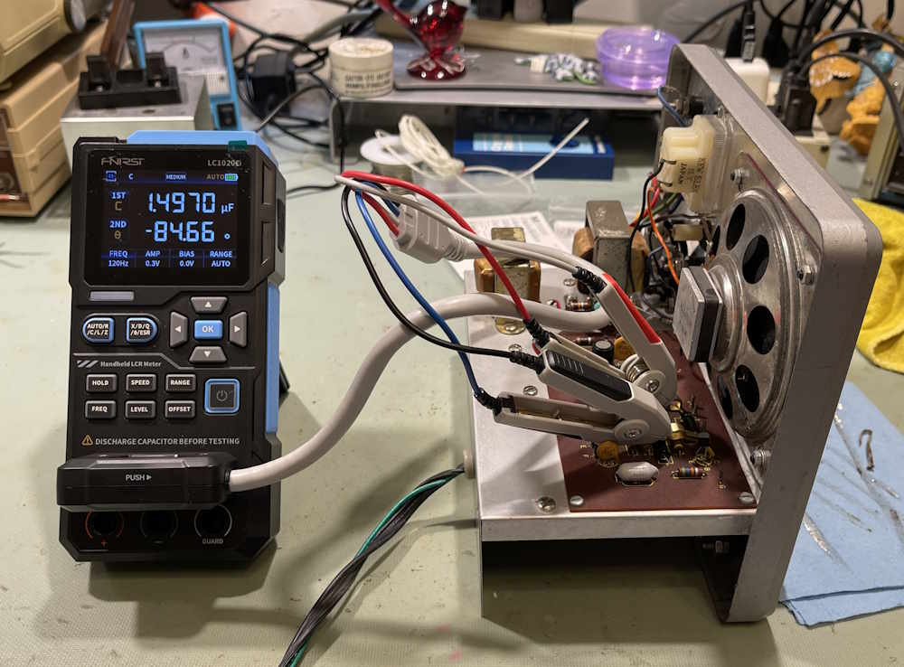
-84°. A perfect capacitor doesn’t exist.
This is part of the EICO 150 repair series, but isn’t an actual part of the repair.
EICO 150 Project Hub: Coming when the project is completed.