Last night, I sat down with the EICO 150 and started to do the final wrapups on the unit.
Apply a signal.
Nothing.
Excuse me, what?
I focused on the function switch, but it seemed to be working properly after some study. I was able to put a signal in after Q1, and have it work, so that really threw me. I was able to bypass the input blocking cap on Q1 and get more signal, but highly distorted. So what’s going on here?
I decided to try the transistor(s) I pulled out for Q1 and Q2, starting with Q1. Removed the new Q1 and just tacked the old one back in. Immediate signal improvement. A check on the new Q1, and it’s just a diode now.
I get a new transistor for Q1 and check it. It’s good…and there it is.
Leads. The pinout on the transistor is different than the OEM unit.
I replace Q1 and Q2 (which is also a diode now) and I have output loud enough to make your ears bleed.
Rookie mistake. That’s on me. Always check your parts, and pay attention to what your tester is telling you.
Next post is actually doing the final tests I wanted to do, and to try and change the sensitivity of the output meter a little. Stay tuned!
I’m not sure why I didn’t run that lead behind the other one, instead of in front. Who knows.
About a decade ago, I interviewed at a small company in a large town. They wanted a tech, and called me via a recruiter. They wanted me to do a test, which I declined at first, but eventually said “yeah, ok, why not.” It was a basic electronics test, and I passed 100% with one question that we had to discuss. We eventually came to the conclusion that yes, their document was rather poorly copied and my interpretation of the symbol used was acceptable because it looked like that.
The interview went well. I was able to competently talk to them about products and technologies, about what they were doing, and how I could possibly integrate myself into that. They stated that if I wanted to explore other avenues of experience, like PCB design or circuit analysis, then they were more than happy to allow that. It really seemed to be a good fit, and I went away feeling good about the interview and my prospects.
A few days go by, and I’m called and offered the job. I’m told the pay rate - base is a few cents more than I made at the time, but that’s not worth the longer drive and hours the company would need, nor did it take into account other payments my current employer gave (and had given) for many years, payments that I could reliably count on and they offered right up until the day the owners had to retire because they couldn’t do it anymore. Things I had mentioned during my initial screening with the recruiter. I was being offered about $1.70 less an hour for this job, and it didn’t include that this company had a higher insurance premium.
I turned it down at that rate but said can we talk about that? No, that was the offer. Take it or leave it. I left it. There was no arguing, no crying, no nothing from the employer. Not even a chance to negotiate. I did end up speaking to the employer a few months later when some things changed in my situation, but they were frosty. No problem, I understand, thank you for taking the time to talk with me.
Fast forward to 2025. A friend and I are going to a hamfest in Southern Ohio. This guy knows people at the company in question, I believe he went to school with some of them. He had done some consulting work for the company, so he was familiar with the people and the owner and talked to them at times. For some reason, during our drive the company came up as in they didn’t offer anything. I can’t remember how we got started on that but this is something on how it went:
Friend: They were mad when you turned that down.
Me: What do you mean?
F: Just that, they were totally p**sed that you didn’t take that job. They were mad. You were their guy, and when you didn’t take it, it really made them angry.
M: I was their guy?
F: Yeah.
M: You know why I didn’t take it.
F: Yeah, it didn’t pay anything. I told them that too.
M: What did they say?
F: They said “That’s what this job pays.”
M: Really?
F: I told them “Well, that’s just not enough, is it?”
The conversation kind of continued along the fact that friend couldn’t get them to move off that “this is what we pay” line of thinking.
So I was their guy, but “that’s what the job pays?” So even if I wasn’t their guy and was just “Hey, I think we can work with him” I’d get the same amount? What? I don’t understand that. I was ready to step into that role, but the company was just “Well, we have a set rate and it doesn’t matter if you’re the god of your discipline or if you’re just some dude.”
It’s probably for the best that I didn’t take that role. It would have been a lateral move for the most part, with company conditions essentially trading like-for-like. It probably would have been interesting, but I wasn’t willng to take a time and pay cut for the job at the time, even though I think we might have been able to work together later. So there’s not many tears shed here, just a “Hmm. What if?”
But the thing I still can’t get over is that attitude. Why even bother if you’re not going to negotiate for the things you want? Why not tell me this up front if you have a set number already chosen? I would have said “No, I’m sorry, I make more than that and we shouldn’t waste our time,” but…time was wasted and people got mad, all because “their guy” decided that being that guy didn’t pay enough - or even what he had at the time.
C’est la vie. Life moves on and we learn what to ask and when. I know they hired someone, but I wonder if they learned what to ask.
This device sat in my rack for many years, both providing power and USB services for various things. It quit back in March, the power supply giving out like switchers do. You can find that post at the bottom of this one.
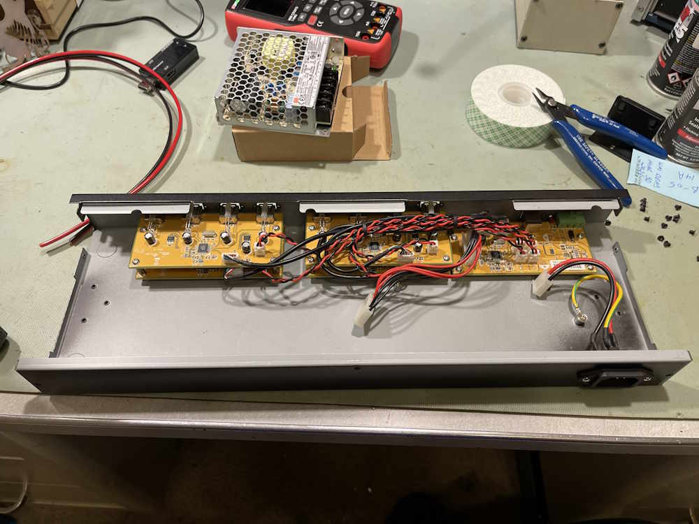
I was going to simply toss the device in the recycle bin, but…high current switchers are so cheap these days, there’s no reason not to fix it. So, let’s open it back up:
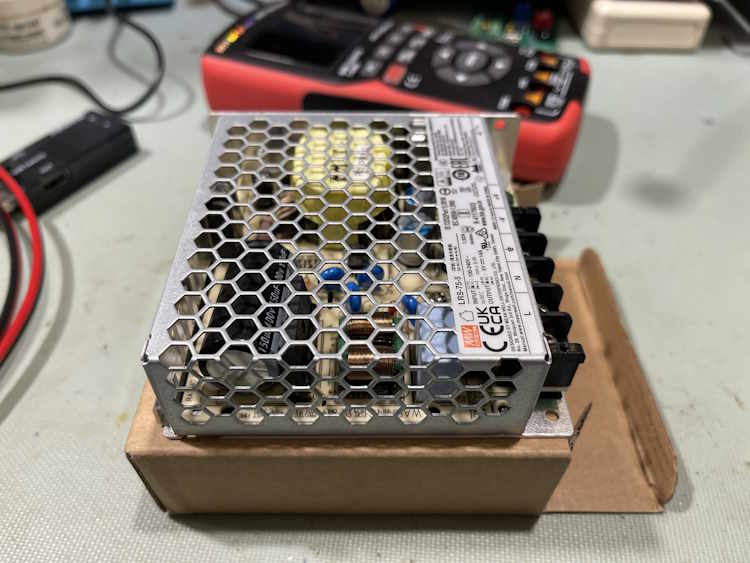
I wasn’t able to get an exact replacement for the supply, so I got a MeanWell equivalent unit. It won’t exactly fit inside, so we’ll make do.
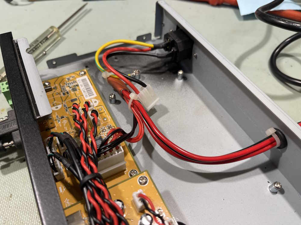
For this task, I drilled a hole in the rear of the chassis and connected the new supply lines directly to the input of the hub using some good 16GA wire. I probably could have used a single strand here, as the internal wiring was somewhat lacking in size - but I used two, because just in case. They’re soldered together, and covered with two layers of shrink tubing.
The other ends were stripped, terminated with an aglet, and screwed into the supply, which now sits on top of the hub chassis. Open frame devices like this aren’t something that I’d put in a place where others could touch, but for me - it’s fine. The hub is back online and working.
There’s a youtube video for this device: Coming soon.
I’m happy that a piece of what could be e-waste is now back in service.
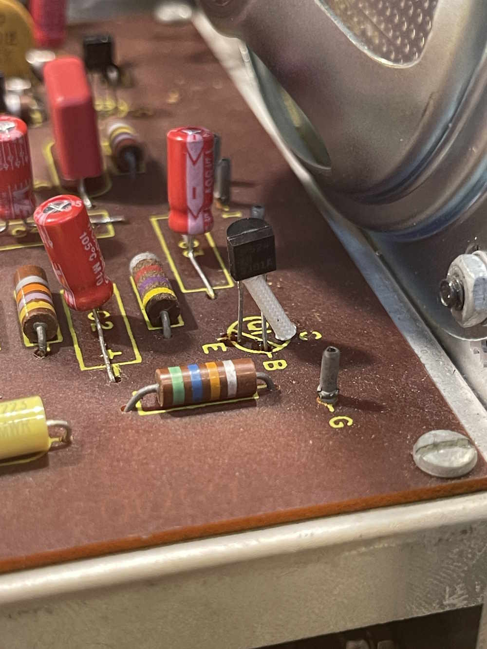
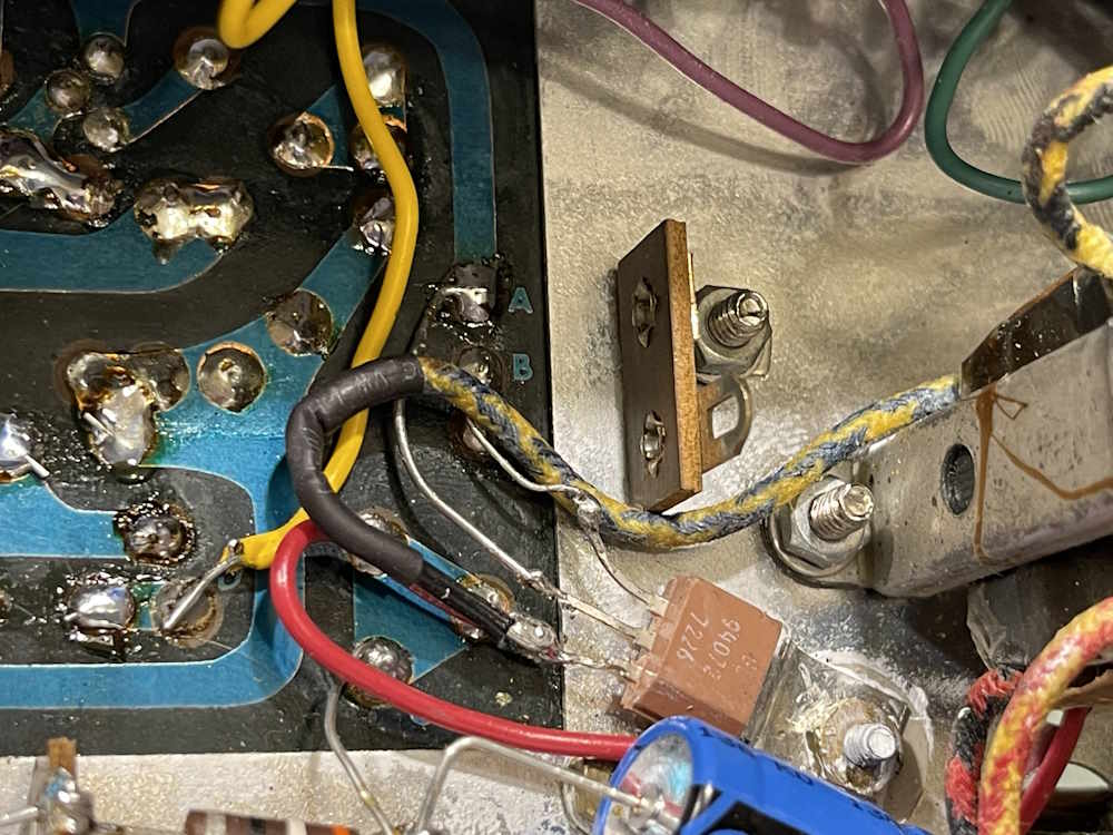
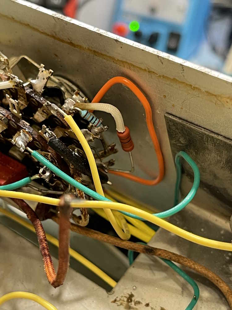
The EICO 150 was back on the bench tonight for some transistors. I started by adding a new terminal for Q4’s output, meter tie point, and transformer input.
I replaced Q4 with a NOS NTE152, new grease, and a new mica insulator of the proper size. Yeah, I got some shiners on the wire there, I tried to be careful but even my orange stick went through the insulation. I’ll get some nail polish and touch those later to coat the wire.
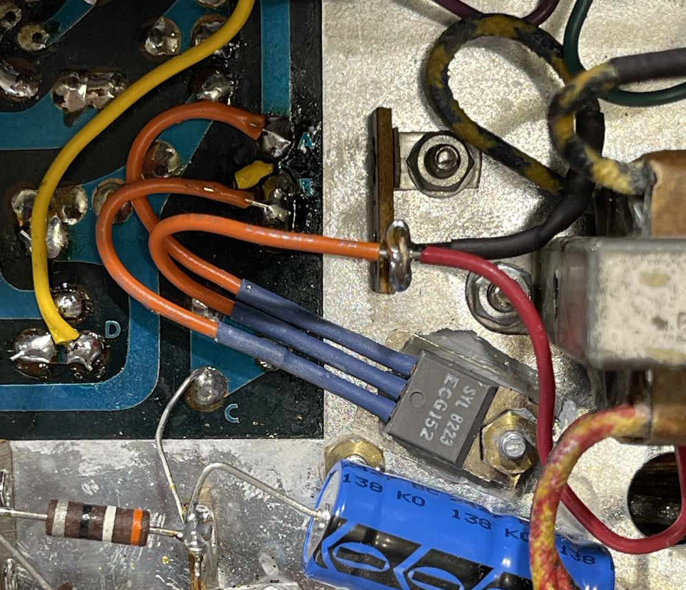
The part I used was an EGC152, which is the same thing as an NTE number, as NTE purchased the ECG line from Philips way back when, who in turn had purchased the line from Sylvania.
Q3 also was replaced at this time, with a generic 2N3906.
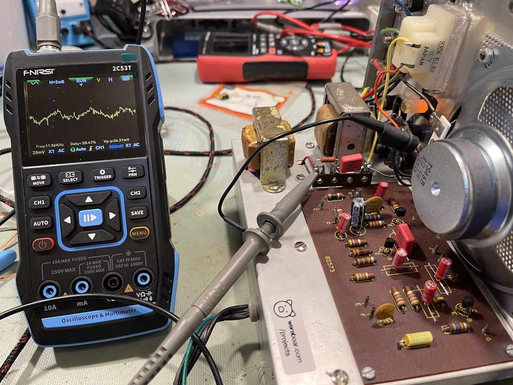
I did some noise testing to see what was going on now:
Noise levels had calmed down substantially:
There was still too much noise, so I went ahead and replaced the other two transistors.
Noise levels calmed down to what I would consider just background nosie. So are modern transistors that much better, or were these simply dying? Well, I replaced Q4 with a device that’s barely 10 years older than the one in there, so it’s certainly not “modern” - I’d have to guess that the transistors were simply breaking down from years of abuse. The Internet seems to think that these are a “replace with capacitors” item for this unit, so maybe there’s some truth in there.
There’s a little more to do, I want to make some measurements for posterity, and adjust the meter drive a little - you really have to crank the gain to get meter deflection, much like an eye tube unit. I want to dial that back some so a comfortable listening level gives noticeable deflection.
Back to the transistors, here’s what I pulled out of the unit:
Q1:
Q1 was originally an EICO number, but the previous owner replaced it with an SK3124, twice. I assume that’s because they blew it out by connecting input to B+ on a tube device. I used a 2N3391A as it’s replacement.
This part would have been an EICO part as well, but it had a Motorola HEP 726 instead. This is a generic AF transistor, ala 2N3904, etc. I used a 2N3391A as it’s replacement.
Here we have our first EICO part. This is the complement to the output transistor, and as such is PNP. Almost any PNP AF transistor will work, but may have to be selected to reduce or prevent oscillations. I used a 2N3906 which seemed to work well.
Here’s the big boy. It’s some EICO number, un-cross-referenceable. It’s an NPN power transistor, almost anything with a few watts of dissipation and an hFe of 100 or so will work here. I used an NTE/ECG152 on the suggestion of the Internets. It recieved a new mica insulator and new grease as well. The old insulator was just a little round piece of mica and the previous owner delicately balanced it under the transistor.
I’m happy with the noise levels here, all I can really hear now is the hum from the power supply. There’s a few things left to do, I want to measure voltages for posterity, and adjust that meter level some. One more part, and then final thoughts. Stay tuned!
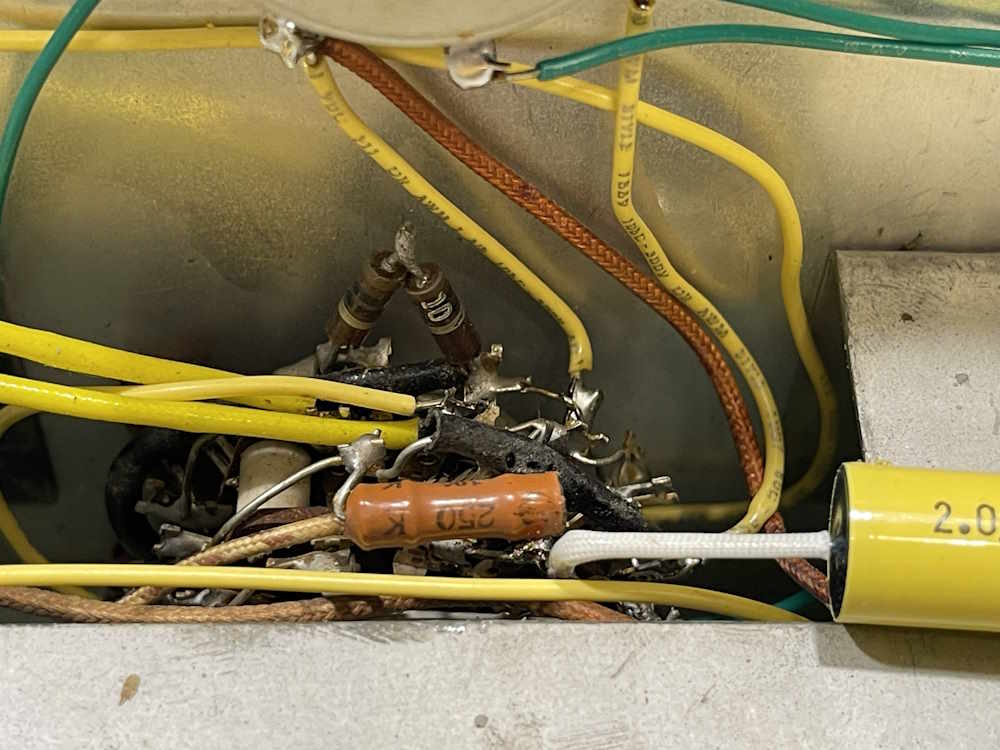
There are only a few more parts to do on the range switch, so let’s get them done. There are two capacitors, a ?? type and a mica type. This is what they looked like:
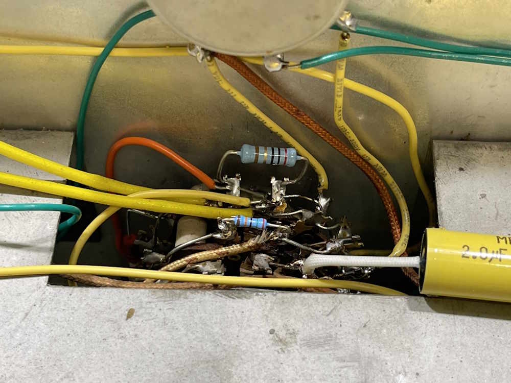
And here’s what they ended up looking like:
I also took the time to replace some of the … more interesting jumper routing on switch terminals, and clean up the terrible solder job. Last thing to take care of on this unit is the power supply area, and I need to decide how I want to lay this one out. Stay tuned!
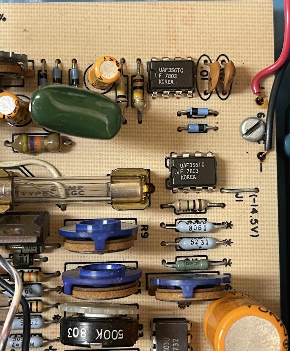
Today’s board is the power supply of a Sabtronics 2000 DVM. Sabtronics is known for being one of the first, if not the first company to offer a hobby priced digital meter. They eventually expanded out into other instruments, into more specialized measurements like True RMS - also at an affordable price. Unfortunately, technology marches on and a company in the USA providing USA-made devices got their lunch eaten by the cheaper array of imports. The devices they offered still have a place today, and those bright “science blue” cases are just as attractive now as they were then.
Here’s the board:
What’s of particular note is, of course, the faint orange script “T” in the upper right hand corner. This board is more akin to the Textolite made at the GE Coshocton plant, but was made there all the same.
I always like finding a piece of home in a device. Especially one that I can use, like this meter. Stay tuned, the “T” will most certainly make an appearance again!
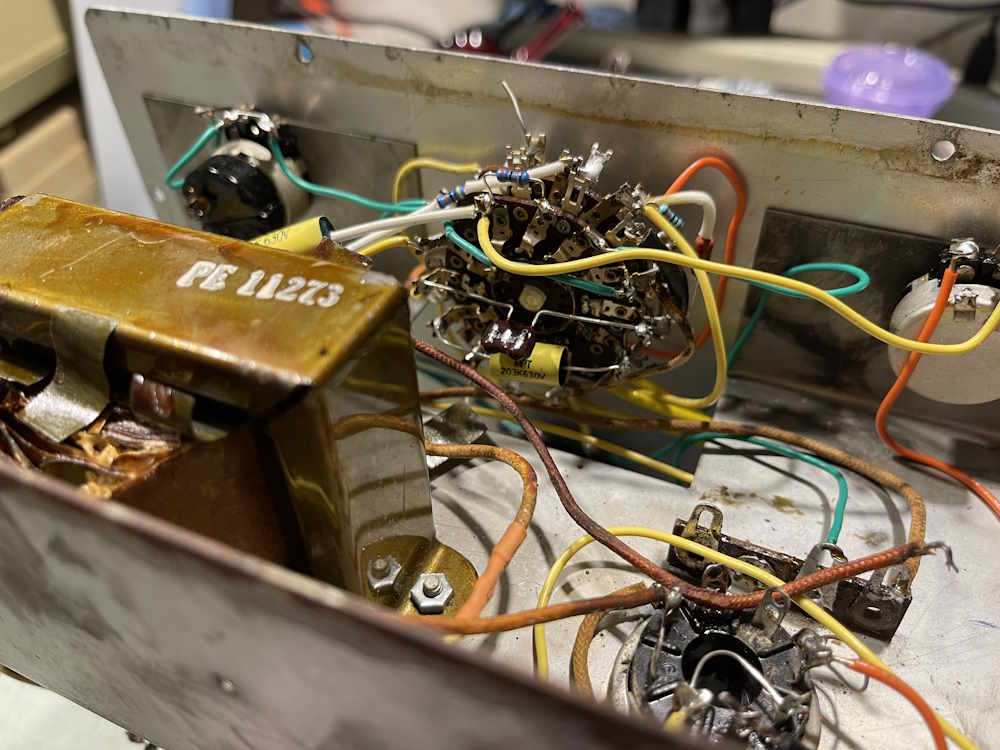
I did some troubleshooting on this device, checked tubes, voltages, transformers, there’s even a video about it that will show up soon and will be linked as soon as it posts. But I overlooked the obvious thing.
You see that switch in the middle of the device marked “Speaker On/Off” Good. You were probably screaming at the screen going “CHECK THE SWITCH!” I finally checked the switch. It was dirty and open. Some Deoxit later, and the tracer now works just fine.
That time was not wasted, however. I did confirm that the filters are good and that the coupling capacitors aren’t leaking, so I feel confident that I can use this device without worrying that it’s going to red-plate a tube - even though that 12CA5 output gets smoking hot.
What’s the takeaway here? Always check the little things because they tend to bite just as hard. That’s all for this device, it goes on the bench as an amp. Plenty more on the EICO 950A to come!
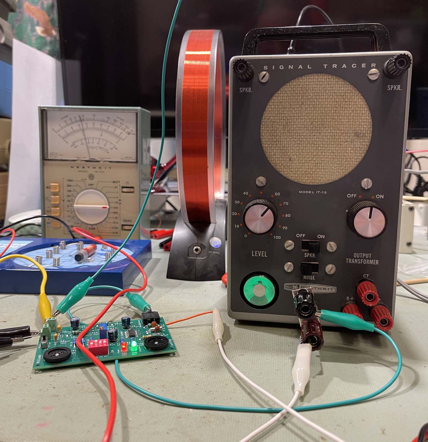
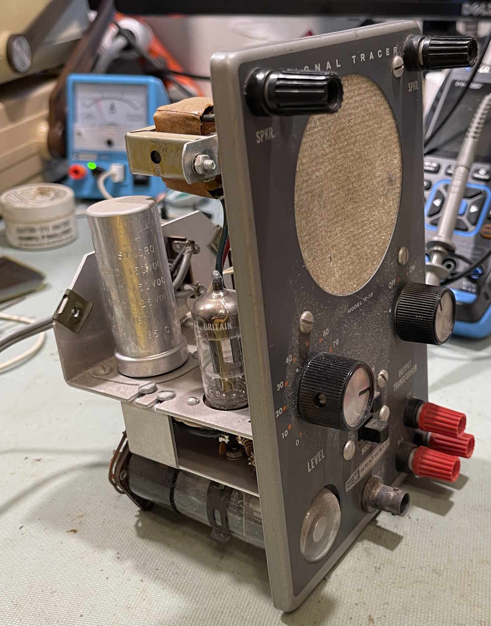
I picked this guy up at Dayton 2026, literally the only signal tracer I saw. This was one of two magic eye laden devices I saw, the other being one of Heathkit’s larger, upright-style R-C bridges. Test equipment of this nature was absent, probably due to the fact that what’s still working is either in collections or is being sold on eBay at the eBay tax rate.
I’ve wanted one of this style for some time, and this one was a couple of sawbucks. Vendor didn’t offer me any advice on it’s status, and I assumed that it did not work. I was correct, the device is silent and the output tube seems to be getting quite warm - much warmer quicker than a simple few minute test would indicate.
I did a bit of troubleshooting to determine if the supply was working, and it is - that will show up later in both a video and a post, as I want to get this device working.
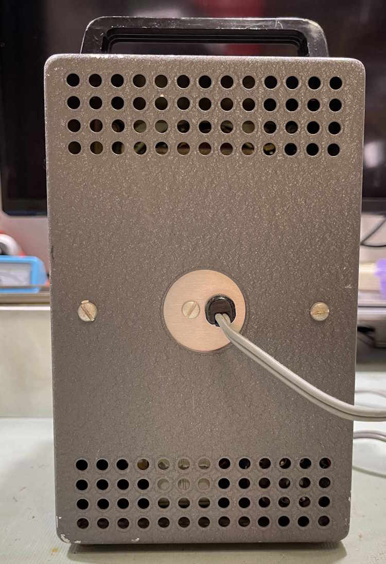
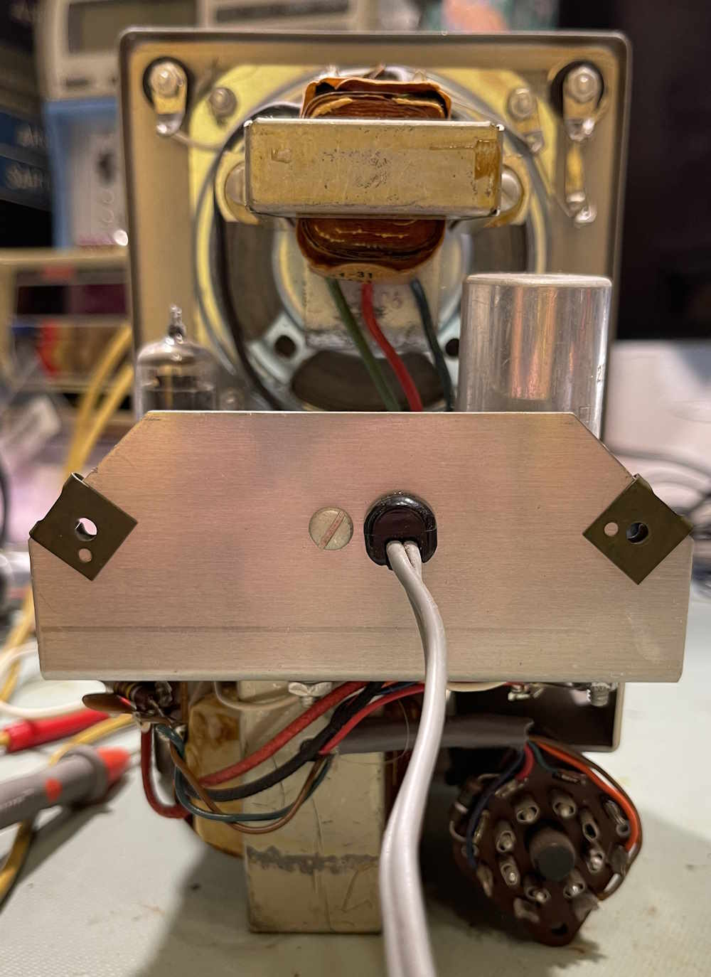
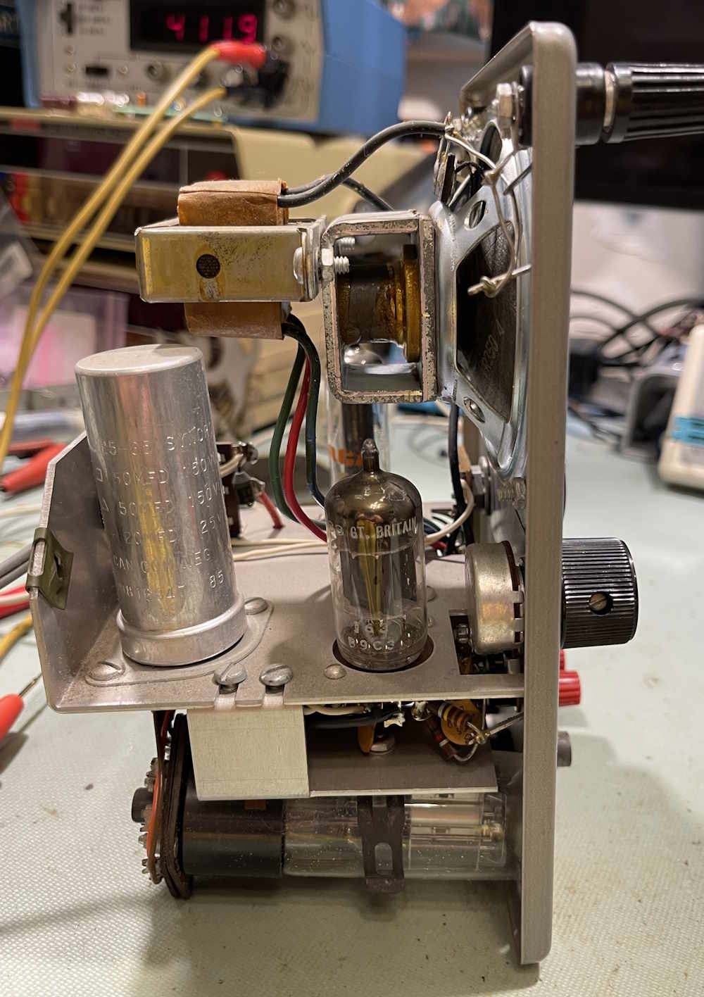
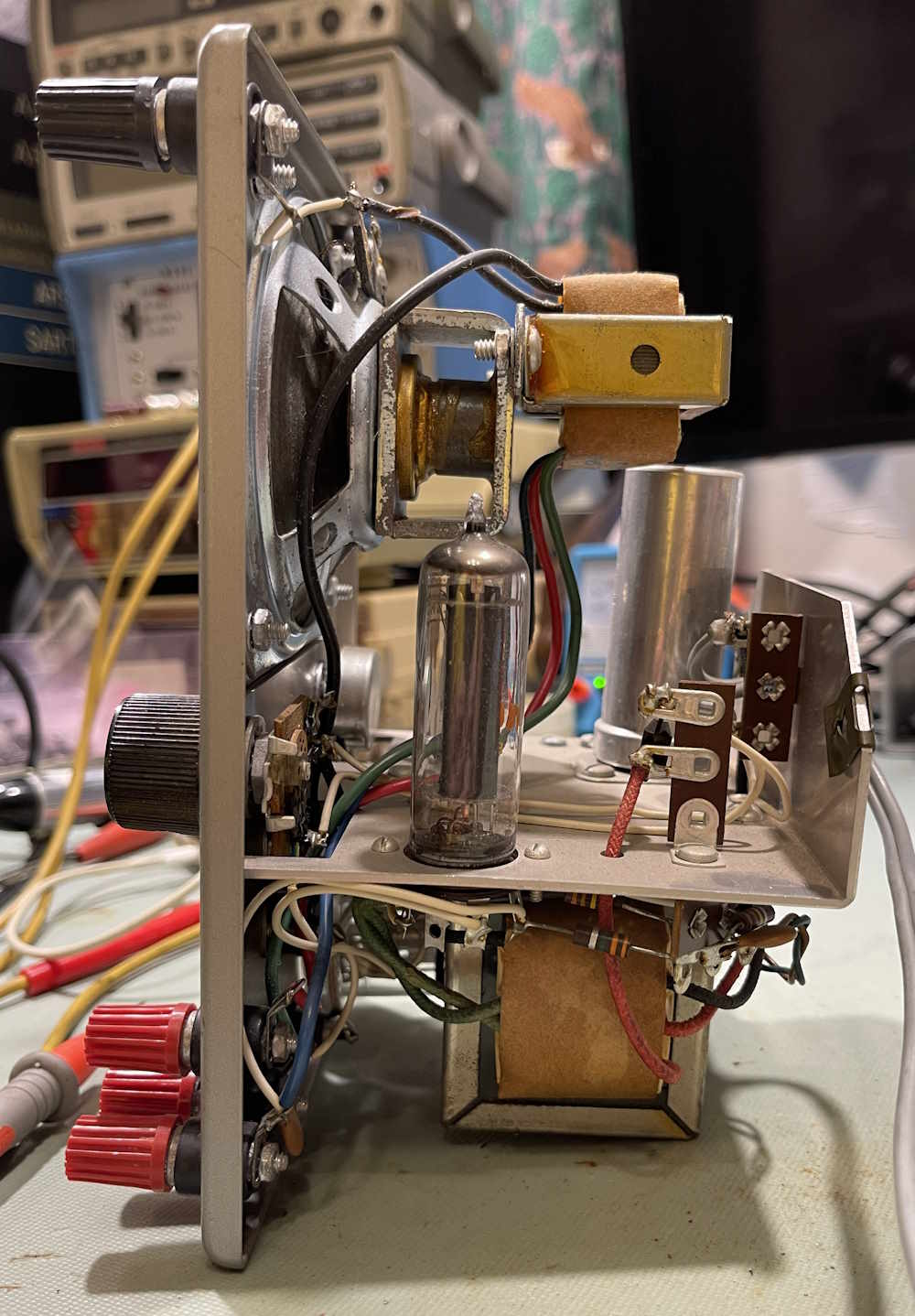
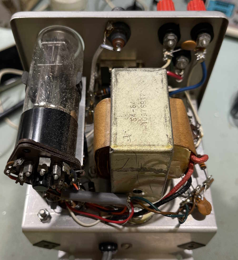
Beyond that, there’s not much to say. Here’s the device photos:
The device is clean but dusty, and hopefully shouldn’t take much to make it talk again. Stay tuned!
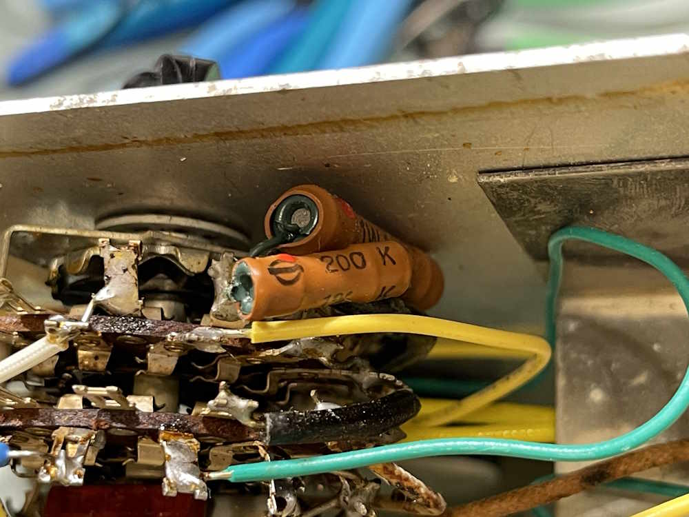
More parts for the EICO 950A, this time concentrating on that center switch. This takes care of the resistors on that switch, but the two capacitors in there will still need replaced.
We’re about 3/5ths of the way done here. The power supply, and some other cleanup remains.
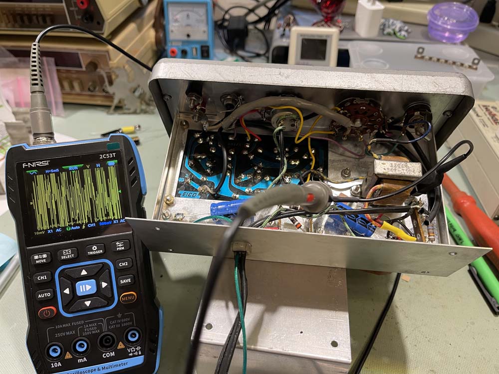
The EICO 150 that was on the bench had a bad speaker. Now it has noise. Lots and lots of noise.
I’m going to put a scope on the transistors to see what they look like, in particular Q3 and Q4, the output pair. This is with minimal gain, no input signal. The test is trying to determine where the noise is coming from. I made a partial determination earlier with a suggested test - unhook the base of Q4 from the circuit. If the noise stays, it’s Q4. If it goes away, it’s back further in the circuit. It went away, so something further back is bad. I’m also going to measure the voltages on each transistor for reference.
Some noise there on the collector. This will also appear on the base of Q4 since they are direct-connect.
Q4
Base
Emitter
Collector (Output)
The signal is being amplified by the output transistor. Perhaps this explains the current draw? The output transistor is doing something instead of being in it’s no output state. What’s causing this? Maybe Q3 is just noisy. Maybe one of those carbon composition resistors is noisy. It’s going to take some more work to make that determination.
Voltages
Measured:
Manual says:
You can see there are some variations here. Further work is needed.


