The Trekster 4-Band Credit-Card-Size-Emergency Radio
Monday, April 27, 2026 at 09:53:32
This is a neat little kit that was provided to me for review.
This is from the same vendor as the crystal radio kit, and can be purchased at the same eBay store. The kit itself is $20, which is really reasonable for a kit like this. it’s got enough parts to keep you busy for a couple of hours, and is what I would consider a “beginner with some experience” level. There’s nothing really here that should prevent someone with a soldering iron and some patience from assembling.
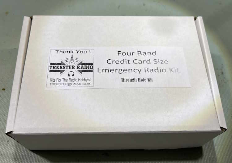
It comes packed, of course, in a neat little box:
Inside the box, we have all of the parts, including a PCB with the main IC soldered in place. You can request the IC be left unsoldered if you prefer to do it yourself, but as SMT is a bit beyond beginner the choice is yours. Advise the seller of your preference when ordering.

Some general notes on building kits
If you’re serious about building stuff like this, purchase or 3-D print a component bender. These are triangular shaped plastic tools with slots in them for various size parts, and the spacing gets bigger (obviously?) as the triangle grows. It makes for neat installation, although it’s not a necessary item. For this particular board, the spacing for resistors and inductors is 0.4”, which is usually the smallest you can bend a 1/4” part and still have enough lead that you’re not damaging the part body.
For marked parts, i.e. parts with a printed value, always try to keep the value face pointed in a direction where you can easily read it. Small capacitors like the 27pF parts in this kit are good examples. While you know what they are now, you may not remember later and having them easily visible is always good practice.
For other parts, like electrolytics and LEDs, never trust that the long lead is the anode side. While this is “common industry language,” I’ve seen parts made with equal, or even opposite leads over the years. Always verify before installation. View the markings on capacitors, measure LEDs with a diode checker if you’re unsure. That minute you spend could save a lot of time in the future.
For parts like capacitors that have a meniscus (coating) that goes down the leads, it’s best to try and raise them up a bit when soldering. This is to prevent the coating from being down in your solder. Electrolytics are similar, except you’re not trying to prevent contamination, you’re giving yourself a little room to see if the capacitor pukes out it’s electrolyte over the years. A small piece of 22ga insulated wire will work wonders here, just use it as a lift under the part as you solder and then pull it out when done.
And last, but not least - while you don’t need to clean the flux off a board, if you want to wash the board, do it before installing things like potentiometers and other parts that can get flux ingress. You don’t want your moving items to become not-moving because it’s gummed up with flux. Be careful if you’re cleaning after everything is installed as not to contaminate moving parts.
The kit itself.
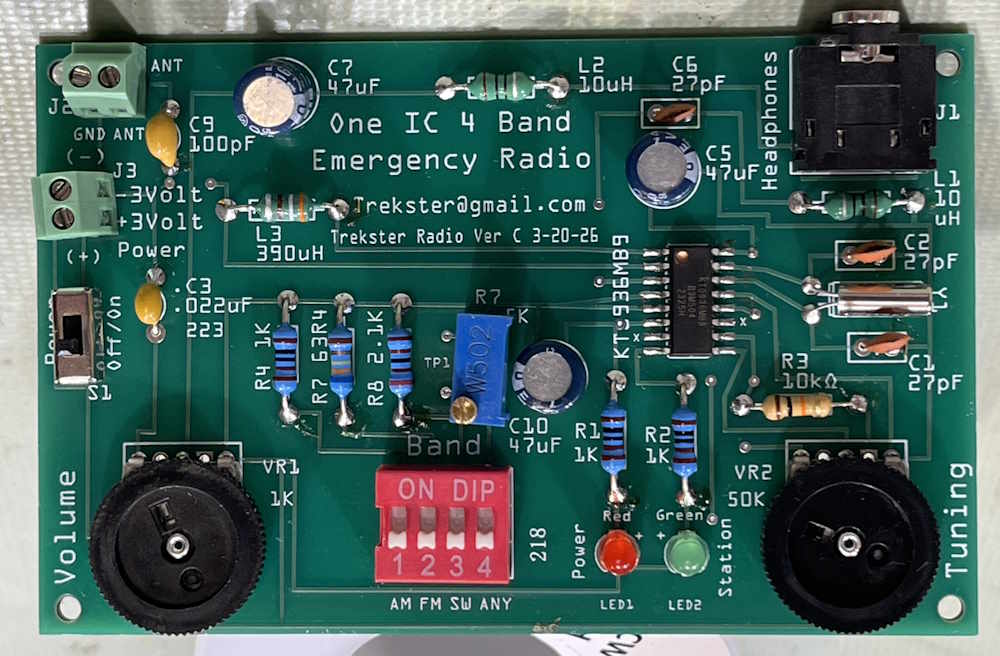
Like the crystal radio kit, this went together easily. The board is well marked, and even without the instruction leaflet you should have no trouble assembling this item if you have any kind of electronics experience. Pay attention to polarities on capacitors and LEDs, of course - everything else is place and solder.
I like to put a component in, tack it quickly on the front side (resistors and inductors,) and then do any forming or cutting of leads on the backside before fully soldering. That’s the “technically proper” way of doing this, form, cut, solder. Diagonal cutters put a lot of stress on a lead, and you can crack joints. While this is unlikely, cut your leads so that you have some small amount of wire sticking up from the board and solder the part in, making sure to pick the lead that’s unsoldered first!
For parts you’re lifting, just hold gently with a finger and get a little solder on your iron tip and quickly hit the joint. Form, cut, and the solder the part in properly, and remove the lift.
It took me about 90 minutes to assemble, but I wasn’t in a hurry. You could probably do this in under an hour if you wanted, but take your time. Make sure you get good flow-through and nice shiny joints. It’s not going anywhere.
I ended up with a nicely populated board:
Testing
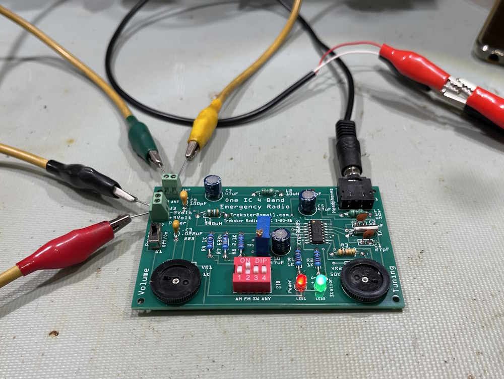
For this test, I set the radio up with some wire leads and used my bench supply to get 3VDC. The creator pipes input voltage in via a terminal, so you could use the included battery box to power the device, or you could use any source of 3V. I have an old rat shack solar array that puts out something around 3V, I’ll give it a try if we ever get a sunny day here in Ohio…this is where the emergency portion of the device shines. You can run this off of anything that has 3V somewhere. Solar, battery, probably even a bleach cell (which I want to try as soon as I get some metal and a couple of ice cube trays!)
Continuing setup, I gave it an earth ground via the local electrical system, and just tossed a cliplead over some stuff for an FM antenna. Audio was provided by my EICO 145 signal tracer, although the device really is intended for a small set of headphones.
How’s well does it work?
Very well! I was able to tune through almost all of the major stations here with only a few of the local lo-watt ones not being present. I would assume, however, that with a proper FM dipole the radio would work much better - but as it stands, it will work with just a random piece of wire which is what you want for a device that’s supposed to be for those oh-crap moments. I need to get someplace less electrically noisy to test the other bands, and will do that as soon as I have the ability.
Power draw on the unit was about 100mA constant, so AAA batteries, if new and fresh, should give you maybe 8 hours of continuous listening. Maybe a little less depending on what kind of headphones you’re driving, and the condition of your batteries.
Final thoughts
One of the really cool things about this kit is the radio IC used tunes with resistance, instead of capacitance. That saves a lot of cost and potential failure points. It’s quite the little marvel when it comes right down to it, and I’m considering what I could use that for in my own projects. It also means no bent plates or corroded capacitance if you store it for a long period.
Beyond that?
This is an extremely attractively priced kit. It’s easy to assemble, and does something useful in the end. My opinion on this is it’s a yes. You want to build a kit that does something? Get one of these. Build it and use it as a bench radio, or test it and stash it with some small tools and wire for those situations where you may not have anything else.
Happy listening! There will be one more review in this series, coming soon!