This thing had a rough life. It doesn’t really work right now save that it lights up and makes glow. Did it ever really work? Well…since I just wrote that, I think you can probably guess what I mean.
I can’t say I’ve seen a device that has corroded wire like this one does. Not all of them, just some.
It’s hard to see, but it’s speckled with green. I checked wires as I went, some needed replaced, some were replaced just because they were in bad shape otherwise.
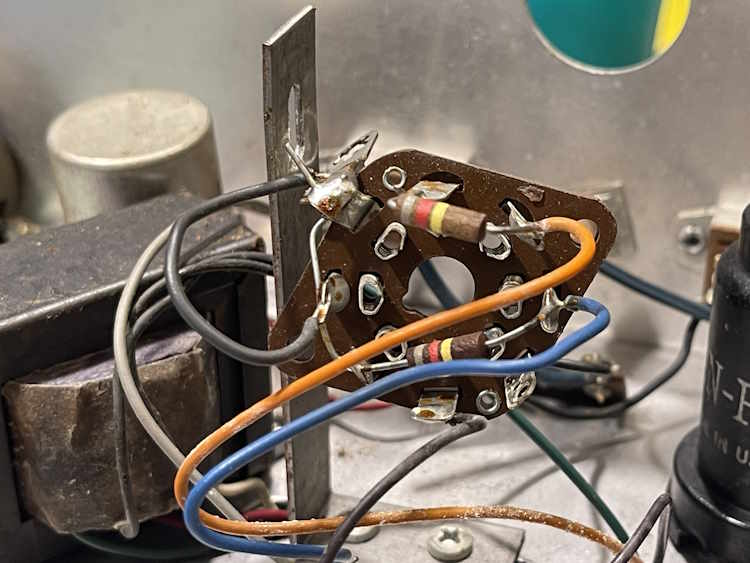
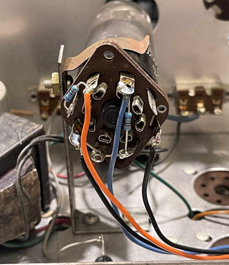
The eye tube socket assembly.
Everything here was attached decently, but stuff just looked bad, and these wires were corroded.
Some new resistors and new wire, and it looks better. Still needs a bit of dressing, but that comes last.
The original builder put the eye tube at a weird slant. While the bracket itself can be moved on a slide, doing so puts the bolt for the bracket up against a terminal strip underneath because it was mounted opposite of how it should have been. That was corrected by just using a longer screw and some nuts as spacers. It’s not like this thing is going anywhere, so mechanical stresses aren’t a concern.
That’s all for the eye tube.
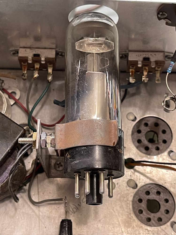
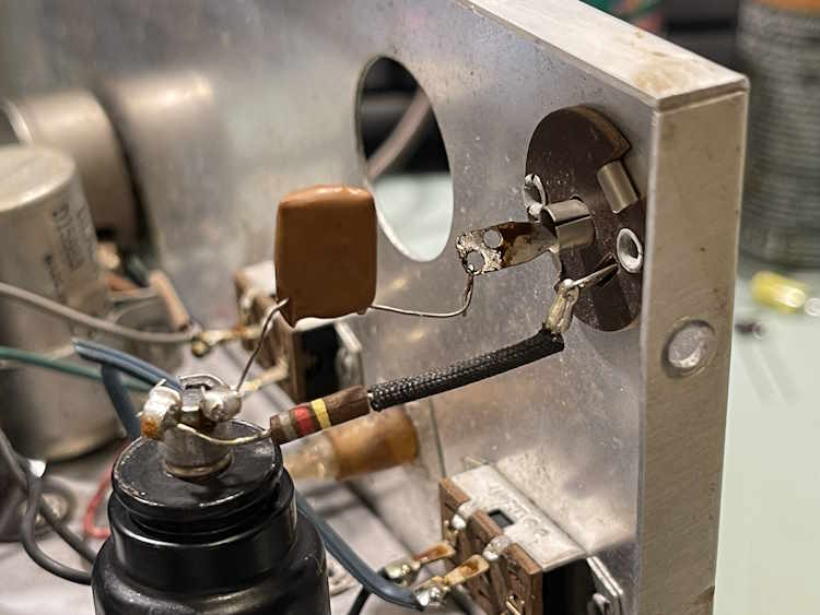
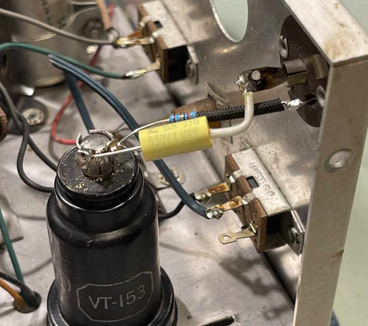
The grid cap for the 12C8.
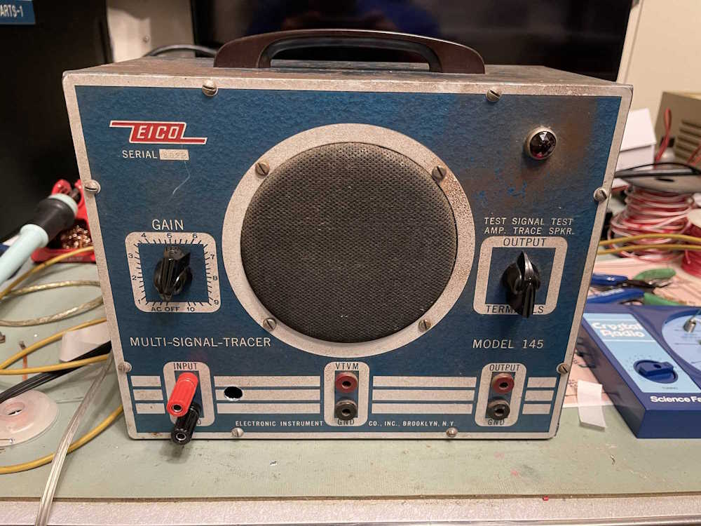
This is the “signal tracer” portion of the unit, and it uses a WWII surplus tube, the VT-153/12C8. This tube was designed for radio service, and exposes one of it’s grids on the plate cap. That’s where audio is fed in for amplification. There are two parts, a resistor to ground that provides bias for the grid and a blocking capacitor for the audio so you don’t get DC in your device that’s under test.
That was easy enough to re-do.
Fairly standard work, there’s really nothing of note. It’s time to move on to the main body of the unit, and all of it’s “none of this matches anything you wrote down!” mess.
Recently, a forum buddy and I talked about capacitor measurement and devices to do such work. I decided, since I have a number of devices and access to a calibrated measurement device, to check a number of parts to see how well each device matches.
Why are we testing capacitance meters?
Simply put, there are many out there on the market under $100, and I have a number of them. I wanted to both know how these performed, and I told the forum I’d see which one performed the best. Thus, the testing.
Introduction and the devices themselves.
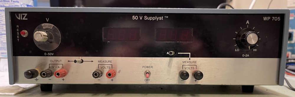
The reference device is an Agilent E4980A. This is a thousands-of-dollars instrument that tells you nearly everything you could need to know about capacitors. It’s calibrated, and has compensated kelvin clips for the measurement end. There are no pictures of this device in situ because, while the facility it’s in says I’m free to use it, they asked that no pictures be taken inside the facility. Sure thing, no prob. You can find pictures of this device online.
For this testing, I wasn’t worried about marked value vs. actual value, although that was recorded for posterity. All of the parts save one is NOS or RFE. These parts were chosen to be representative of the components you would find inside of an older device, especially the kind that typically graces my bench.
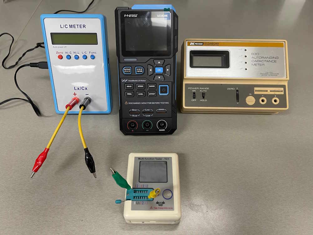
Capacitance meters were chosen based on the fact that you can get them, or their re-badged cousins easily at a show or online. Those devices are:
A generic L/C meter from an online shop. No name.
A FNIRSI LC1020E.
A B&K Precision Model 830 Autoranging Capacitance Meter.
A NIU M-Tester from Dayton 2016.
The leads in the picture were used for all devices except the m-tester, which needed the jig clips shown. These were made by me the night before testing using stock from my parts bins.
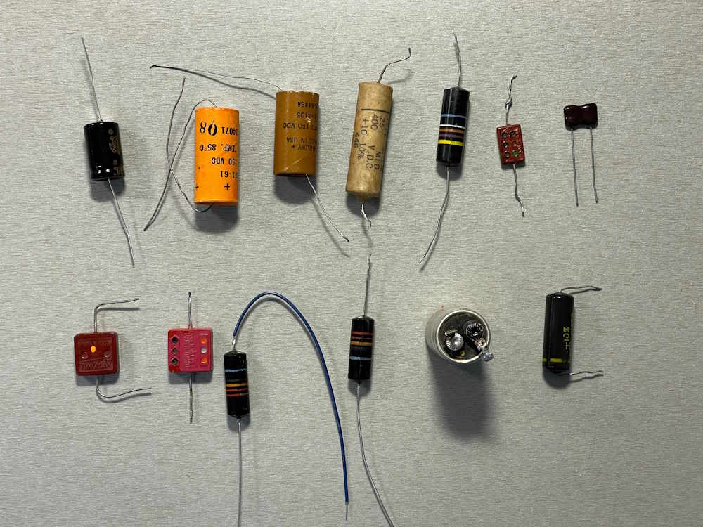
The parts that we’re testing.
Components were either things I had in storage, things I had bought for projects, or components removed from devices. All save the new one on the top left were suspect, leakage/etc. did not factor in to my testing.
They are, from left to right, top to bottom:
A Supertech wet, 100μF, new.
A GI 50μF dry, NOS.
A Mallory dry, 20μF, RFE
A Good*All wax paper 0.25μF, RFE.
A Bumblebee dry paper, 0.047μF, RFE.
A Solar postage stamp, 100pF, RFE.
A Sangamo Silver Mica dogbone, 1nF, new.
A Aerovox postage stamp, 6300pF, NOS.
A CornellDublier postage stamp, 10000pF, RFE.
A Bumblebee paper in oil, 0.022μF, blue wire lead, RFE. (Leaks oil.)
A Bumblebee paper in oil, 0.022uF, bare wire lead, RFE. (no leaks yet!)
A Sprague wet, 15μF, RFE.
A GI encapsulated paper, 0.033μF, RFE.
New = new part purchased within the last few years.
NOS = an old part, otherwise unused.
RFE = Removed From Equipment.
wet = wet electrolytic
dry = dry electrolytic
The rest should be self explanatory.
The postage stamps are presumed to be mica, but it’s hard to tell. Paper was packaged that way, so no assumptions are being made to their construction.
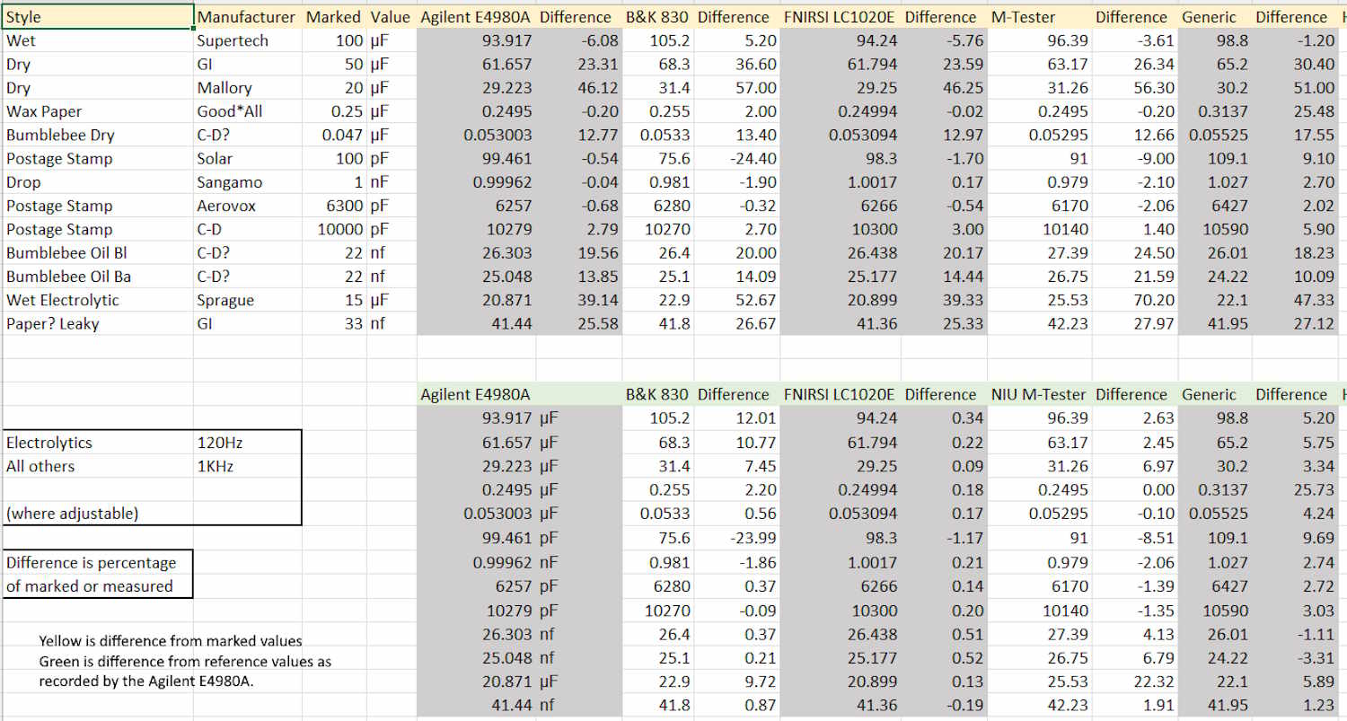
The testing methodology and notes.
Testing was simply connecting the unknown, adjusting the frequency (if possible,) and recording the value. Test frequencies used were:
120Hz - All electrolytics
1KHz - All others
The reason for this is these meters use a component of measurement called reactance. This is basically resistance of the part, with a phase angle. Geometry students will know that as a phasor, a complex number with an imaginary √-1 component. This complex number is a resistance value and an angle, -90° for a perfect capacitor.
You can’t measure DC resistance of a capacitor because it holds a static charge on it’s plates, and presents an open to your meter. AC, however, “goes through a capacitor like piss through a tin horn,” according to my first electronics instructor, Mr. Norman. This complex number is why you have a capacitor on motors. Not only does the capacitor help provide a kick to start the motor (the storage capacity of the device,) but the capacitance tries to drag the opposite force of the motor’s inductance back to zero where you only pay for the actual power used, not the power represented by the complex number. It’s basically black magic with some science added for flavor.
Regardless, data was recorded from all devices and compared to the reference unit. I originally thought that the venerable B&K 830 would provide the best measurement, as it was a fairly expensive instrument sold to industry, but that was not the case. I’m assuming this is because it doesn’t change the measurement frequency, but tries to use a best approximation for everything.
The FNIRSI device, however, came within 0.5% of the Agilent reference except on a very small value part, of which is probably due to capacitance of the leads…1 part in 100 is 1%, so any small deviation is going to show up. It’s far better than you’d need as a hobbyist and shows how far we’ve come in tech. The M-Tester and the B&K 830 kind of went around themselves competing for 2nd place, but the M-Tester offers other component tests and is really good enough for most stuff. It’s a fairly valuable device on my bench.
I realized after the fact that the FNIRSI device came with kelvin clips - I’ll re-run the test at a later date and publish new data.
The blue generic device came in third. It’s not terribly accurate, but it did the job. If you needed something and were working on old equipment, this device would satisfy your needs.
Conclusions.
The FNIRSI LC1020E, at about $80, is a superb value and will get you industrial bench performance at a hobby price. This is without using the compensated clips, so you get an instrument with leads you can reliably expect to provide good data, assuming you can set it up. The device does far more than this, and offers a staggering amount of data on the parts.
The M-Tester is a good, quick way to check all common parts, including common semiconductors. While not as accurate, they’re cheap, good enough, and should be in your travel bag if you do electronics of any sort.
The B&K 830 is meh. These still show up on the secondary market, but really don’t do anything that modern devices can’t. They are fairly rugged and can be powered from the line, so if you need a good-enough device with those parameters this is your man.
The generic one is nah. If you can get one for a couple bucks at a show, sure. It’s good to have a 4th opinion. Otherwise? Pass.
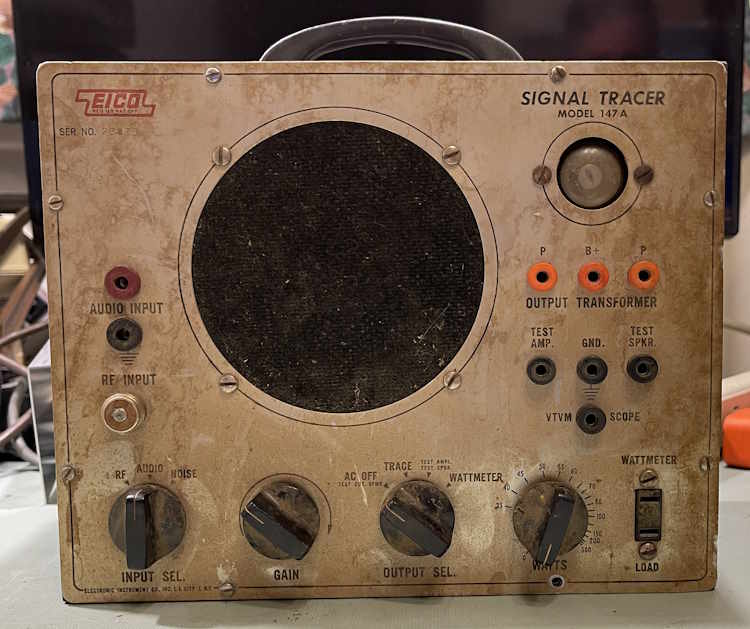
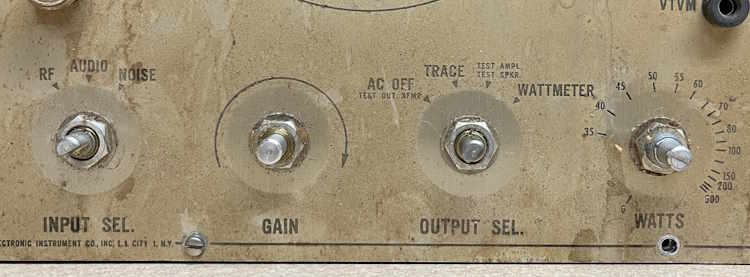
This is the second EICO 147A chassis that I purchased from the Early Television Museum - this one was considerably more dirty than the first, and looked to have had coffee spilled on it at some point. The initial analysis after acquisition is posted here if you’d like to read it.
The second chassis was very dirty on the outside. The front was covered with caked-on dirt, as was the case.
I was concerned that this was a smoker’s choice, but it looks like the dirt is just dirt. The space underneath the knobs was clean.
The front cleaned up well with 409, as did the case itself. I got a weird hit of old coffee while scrubbing the case itself…
It was mostly a matter of just some time and elbow grease. This one has certainly seen some use, some of the front panel sides are chewed up, and the bottom of the case has some rust where the paint was torn off.
This one is much worse inside than the other, and looks to have been assembled by an inexperienced builder. But, it still needs the same part as the first chassis…
This one is most certainly wax paper. It tested fine, but it’s still getting replaced. A new film capacitor was installed in it’s place.
This unit has a mod on back where a previous owner put a mini twist-lock plug on it. I replaced the cord on the socket end, and it’s polarized…but the plug in the unit itself is not. You can push the socket on any direction, so a label was applied to let the operator know that the socket needs to be attached in a certain direction:
Does it work? There was really no reason it should not work because it did before I started, but yes. Everything is now operational.
This one may eventually end up for sale, as I don’t need three of these devices. Who knows? (I think it’s going into work with me as a useable display piece.)
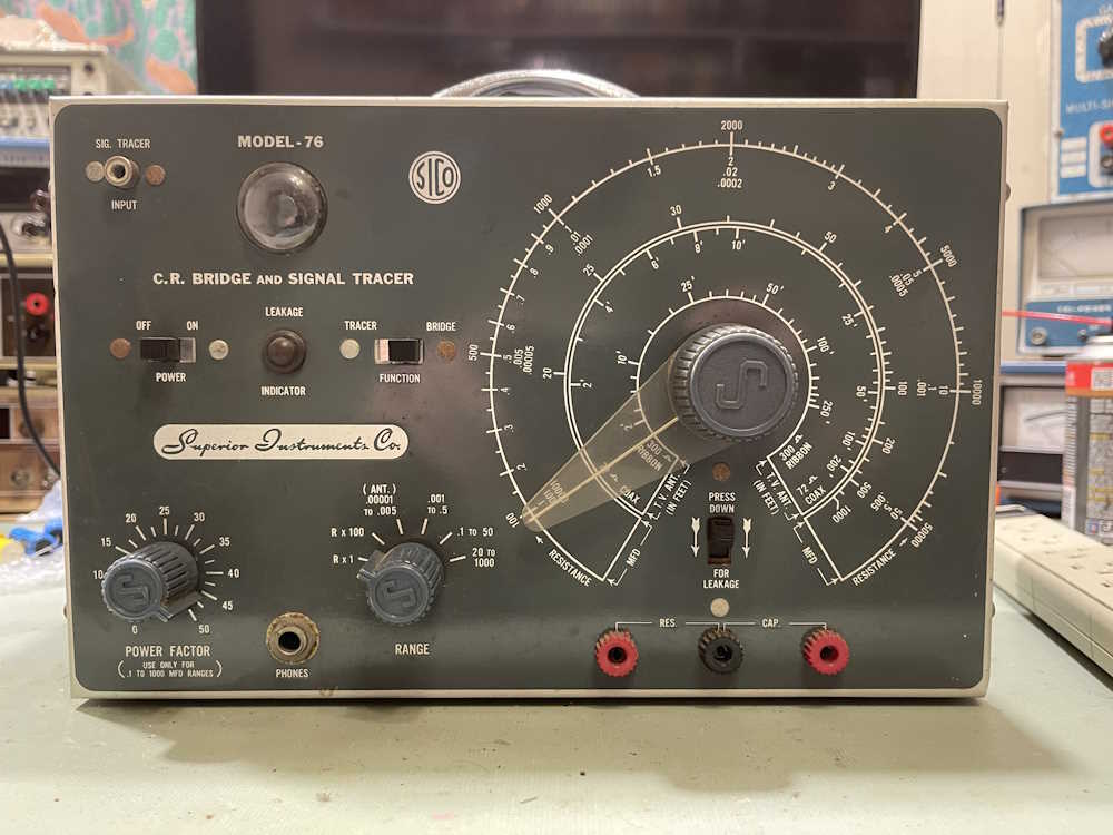
The Superior Instruments Co. Model 76 is currently on the bench for a rebuild, and the Cuyahoga Falls Hamfest is coming up soon. Stay tuned!
Welcome to visitors from the Home Assistant Community, and thank you for visiting. This is a personal blog where I primarily do older equipment repair/rebuild, but I sometimes will pick up a piece like the one below. There are a few other stories related to HA in the archives, click on the “Automation” link in the categories section of the sidebar to get a listing of everything so far.
Recently, I tore down an Ikea Inspelning smart plug in order to see if it was able to be modified to be always on. It was, and you can find that teardown and analysis here.
Well, for some reason, Ikea decided to abandon the tested and working ZigBee protocol plugs and go to a Matter-based mess. Why? I have no idea save that it could potentially allow them to put devices on WiFi later - or perhaps they just jumped on the latest Thing like many companies do without any soul-searching as to if this is a good idea.
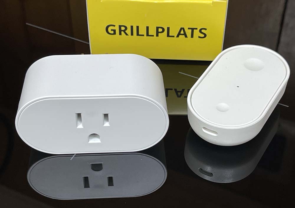
Regardless, the new Grillplats (Grilling Place, or some area where you have an outdoor grill for cooking) has arrived and is for sale at stores. If this is like any other Ikea devices of this nature, they will sell out immediately.
What’s in the Grillplats box
(All of my experiences are coming from using Home Assistant. YMMV here.)
The plug comes in the standard white box with a yellow top listing the name. Inside, you get both a plug and one of the new Matter-enabled Billresa (road trip) buttons. The button features two separate buttons that can be detected as single push, double push, or long push. Sometimes. Home Assistant doesn’t seem to be able to reliably keep one of these active without pinging it at times, or doing a song and dance to make it work again. That’s not the point of this article, however.
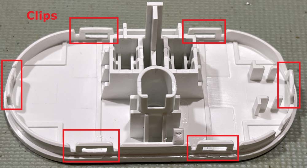
The new device is not as wide as the older Inspelning, and has a white face instead of the gray face. This one tears apart much like it’s older brother - there are six clips around the outside of the device. Two on top, two on bottom, and one on either side. You’ll need something like an iOpener to pry the unit open and pop the clips. Note that because the top panel isn’t as wide, it’s less flexible and doesn’t want to pop as well as the older one. Be gentle here, I mangled a side clip when tearing apart.
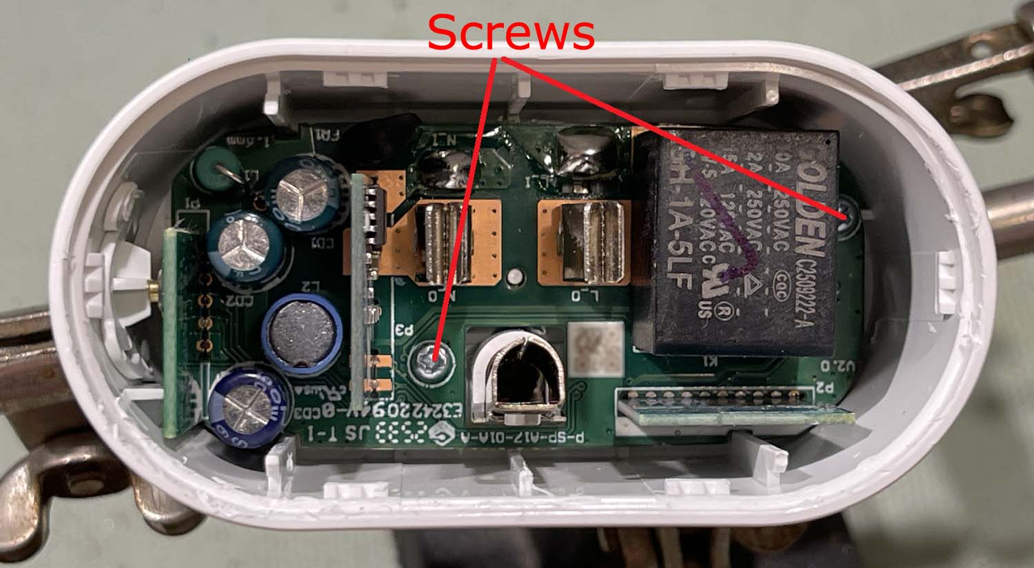
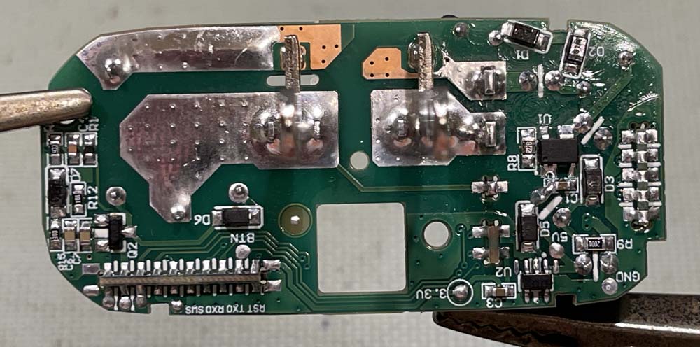
The board itself looks like a more compact and kind of janky version of the previous model. It’s very similar, save that components are packed tighter. Two screws hold the board into the case:
To remove the board, remove these two screws then gently press the assembly down on a hard surface. The board should slide up, then you can remove it by gently pulling on something. I usually use the combination of the “L” socket and the relay as a gripping point. The board assembly just lifts out at this point, and the safety ground plug will come out as it’s not attached to anything.
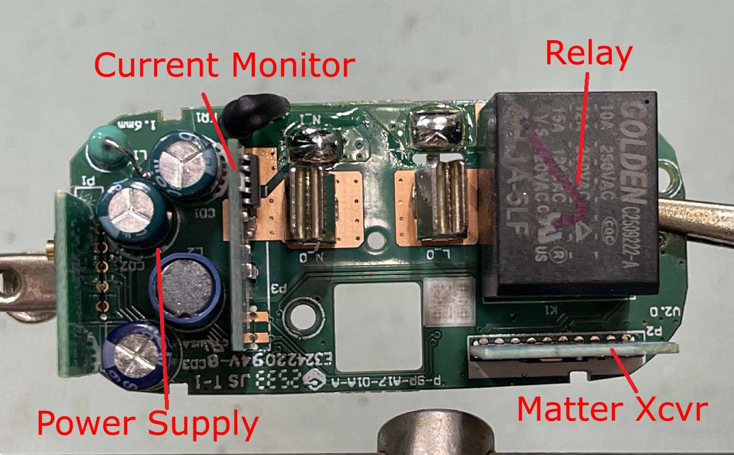
Most things in here seem to be similar to the previous gen. Power supply is a bit more compact, but they’ve put the dropping resistor in the corner away from the capacitors. Any heat generated, assuming your outlets have the ground on the bottom, will rise up away from the capactors. They’ll still dry out and fail, of course, seeing as they’re the cheapest you can get. Other than that, you have the power monitoring board, a new Matter transceiver, and a cheap as chips relay. I didn’t try it, but I suspect you could lift the Matter board and put it in one of the older devices.
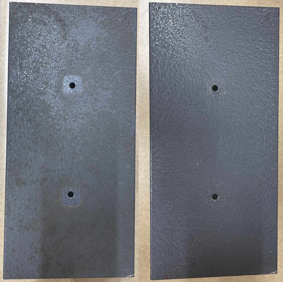
The back is similar to the older unit as well, with two big pads where the AC rides in the unit. This one can be easily modified to make an always on device as well by jumping those two pads with a heavy piece of copper wire.
As before, if you are tearing these down and working with them, you need to remember that there are potentially lethal voltages in here. This can kill you and cause property damage. This information is provided simply so you know what’s inside of the device without tearing it apart, anything else is on you. If you don’t know what you’re doing - don’t do it!
Putting it back together is, of course, the opposite of disassembly. Push the board back in, replace the screws, replace the ground plug, and pop the top back on.
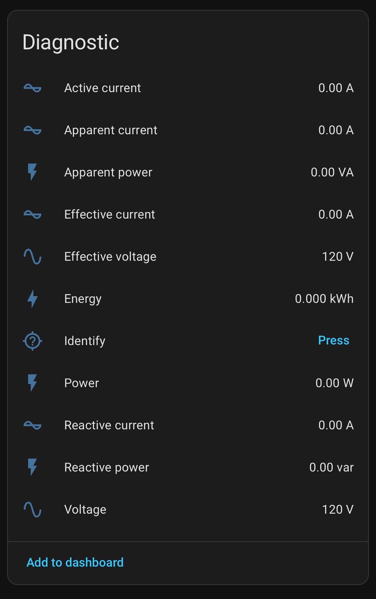
The unit itself reports a lot more than the last one:
Conclusions regarding the Ikea Grillplats plug
This seems to be a worthy counterpart to the previous unit, even if Matter seems to be a bit more janky when dealing with Home Assistant. It can be modified to provide always-on current monitoring. Will it last? Time will tell.
A few weeks ago, I picked up a couple of EICO 147A signal tracers from a local museum - partly with cash, and partly with trade for some other materials that may be more useful to them. I’m going to be working with the “clean” one.
I’ve already verified this works, and that it doesn’t seem to be doing anything unusual. For this project, it’s going to be a little bit of cleanup and replacing two of the three items inside that could potentially be an issue.
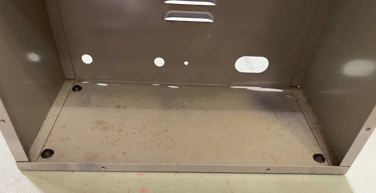
But first, a bit of cabinet cleaning.
These devices had been sitting in a garage for a while, and were dirty both from that and the general accumulation of grime from ages of use. I took the time to wash the cabinet down with some soap and degreaser.
The first item is this molded capacitor. It’s probably paper, but we don’t know.
And, it’s gone.
Surprisingly, it’s still good. This thing must not have seen a lot of use.
I’m going to put a new film cap in it’s place.
A note on this one: This is a part that’s in the wattmeter circuit. It’s unlikely that the wattmeter will ever be used, but it is in the circuit. The electrolytics should also be replaced, but they don’t seem to be in terrible condition for the age. That will be a later project.
The new part gets sized for replacement.
Before being soldered in.
The only thing left to do is replace the power cord with a nice new polarized unit. The neutral goes to the wattmeter socket so there’s no live AC when the power switch is off.
Some contact cleaner on the switches, and it all tests out fine. I’m going to pull the knobs and wash them, as well as give it a good panel cleaning before buttoning it up. I’ll see if I can pick up a capacitor replacement wafer at Dayton this year.
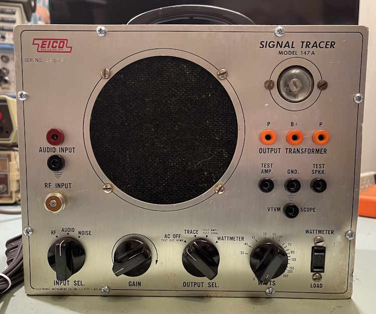
The front panel of the unit looks to just have some surface dirt, as aluminum can’t rust:
The front cleaned up nicely.
The unit was working beforehand, so a quick check and it’s still operational. I’m not really sure what I’m going to do with it, this one may end up at work as a benchtop music amp because why not?
The only issue here is the white paint used as an indicator on the knobs comes out with washing, or even a good wipe with a cloth. I need to find some way of re-doing that, I’m sure that a method is out there. I just need to look.
I’ll be examining (and cleaning) the other chassis soon, stay tuned!
If you’ve been around for any length of time, you’ve probably heard the term X10 thrown around. This is doubly true of anyone who has had an interest in home automation, as X10 is the granddaddy of all consumer controllers. If you haven’t been around since the 70s, you may know X10 from those creepy “Spy on half-naked women next door” camera ads from the early days of the Internet.
X10 was nvented by a Scottish company (Pico) in 1975 and marketed by BSR (the cheap turntable company!) it was eventually picked up by multiple vendors. Leviton made modules for BSR, and later simply became white label devices or X10 Powerhouse branded units. GE offered Home Minder. Radio Shack’s brand was Plug ‘n Power. Stanley Tools sold Lightmaker. IBM used Home Director. RCA offered Home Control devices. Magnavox, Sears - countless others with names from the past offered them. There were other, smaller names that had all kind of doodads and interfaces that spoke X10, and GE even had a set-top programming box that was just downright futuristic. There’s a wealth of devices out there, and it’s still in use - albeit at a much lower rate than it was in the past due to the uptake of cheap wireless devices.
But, the stuff is still there and it’s still just as useful as it was way back when, especially now that noisy CF lamps have basically vanished.
X10: How does it work?
X10 is a home automation system that uses digital pulses that ride on the AC line to address modules. It uses a “house” code, a 16 bit number, followed by some “key” codes. The House and Key are heard by the entire system, but only the module with the appropriate settings will respond, unless it’s a ALL code. The good. bad, and ugly of this system is that you can have any number of modules with the same address because they don’t talk back, but the bad is they don’t talk back so you don’t know if they responded to the command. The ugly is since the signal is on the AC line, it can be interrupted by noise, or lost due to distance from the controller to the listener.
Why use it when zigbee, zwave, and matter wireless devices exist?
There’s a massive base of X10 products out there, and some work without the need for heavy lifting. That is, you can have standalone clocks and controllers that don’t boot and don’t require an OS to continue working. There are modules, remotes, controllers of all types, even landline phone interfaces available should you have such items available.
For example, my X10 system contains the following things:
A BSR Ultrasonic Remote Control base unit (remote not shown)
A Stanley Lightmaker desktop controller
A Stanley Lightmaker Clock Controller
The clock controller is the failsafe for the system. If power fails and the system shuts down when I’m not there, then power resumes, the battery backed up clock will still perform basic functionality - no network connections needed. It handles what I consider to be important lighting to make the house look lived in - main rooms, outside doors, and other things of interest. However, I’d still like to talk to these devices with Home Assistant. I’ve found that there are three ways to do that, but…there are caveats to each method.
So, how to actually talk to X10 with Home Assistant?
The first is the official way. This uses an intermediary called “HEYU” with a module called a CM11A. This is a hardware serial interface between the controller and the power line. It has the capability to both convey X10 signals, as well as store simple programs. HEYU is an old program that translates commands to X10 format for the CM11A.
HEYU is pronounced exactly how it looks: Hey You! - the author states it was so named because he was always yelling “Hey, you! Turn off the light!”
So, why not use this?
Simply put, if you’re running HAOS, you can’t. There’s no mortal-friendly way to build HEYU and put it inside the container that holds Home Assistant. The official documentation that Nabu Casu offers for this is, as per their SOP, quite sparse on the matter and doesn’t offer any insight at all.
While I realize that X10 is quite old and not many people are using it, offering an official integration in this halfway manner is kind of the way Home Assistant works.
All is not lost. There are two ways that you can talk to X10 devices without the official integration.
Method 1: HEYU with BlueLava on a remote machine
So there’s another term. BlueLava…what is that? It’s an old CGI script that provides a user interface for HEYU. The interesting thing about this script is it passes a URL that does the work, so by pasting a URL into your browser, you can cause BlueLava to trigger an X10 command.
I already have a BlueLava/HEYU system, and Home Assistant can CURL a URL, so this is the method I’ll be investigating in the next part of this series.
Method 2: Lots of weird hardware
The second way I can see doing this is to use one of the many remote pendants X10 has, coupled with some sort of zigbee/matter/etc. addressable switch, like the ones offered by Shelly (among others.) This requires a lot of soldering and disassembly and isn’t really a friendly way of doing it. I’ll probably not look at this one unless I get a wild hair and simply want to make it work for … reasons.
What next?
In the next part of this series, I’m going to investigate calling specific URLs to the machine that hosts my current controller. Stay tuned!
This past weekend, I took some materials over to the Early Television Museum in Hilliard, Ohio. This consisted of some of the things you’ve seen here, including the big TRF radio that had a bad output transformer, as well as some other equipment that hopefully they can get a few bucks out of. If you’re in this area and have an interest in older technology - or simply would like to see some of the marvels of previous ages - this is an excellent stop and I highly suggest it.
However…when I was there last year for their fall swap, there was an EICO 147a tracer sitting amongst the other items. I assumed that it was part of the auction material and didn’t pay any attention to it - but it was still sitting there when I was on site this past Saturday. There was also a second unit, quite dirty. I made an offer on both, we agreed, and I took them home.
Why? I don’t know. I’m a silly little wereboar, I guess.
So, what did I get?
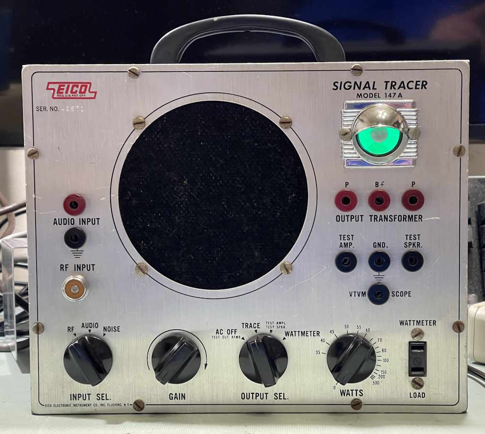
Here’s the clean unit. What caught my eye was the addition of the eye-tube cover someone put on there in years past.
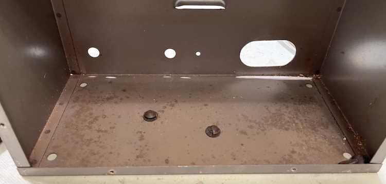
It’s got a little dirt and grime, but overall is in great shape for a garage find. The inside of the cabinet is in equally decent condition. A little surface discoloration, but nothing I’m concerned about.
The outside of the cabinet has the normal scuffs and dirt. A quick wash with some 409 will take care of that.
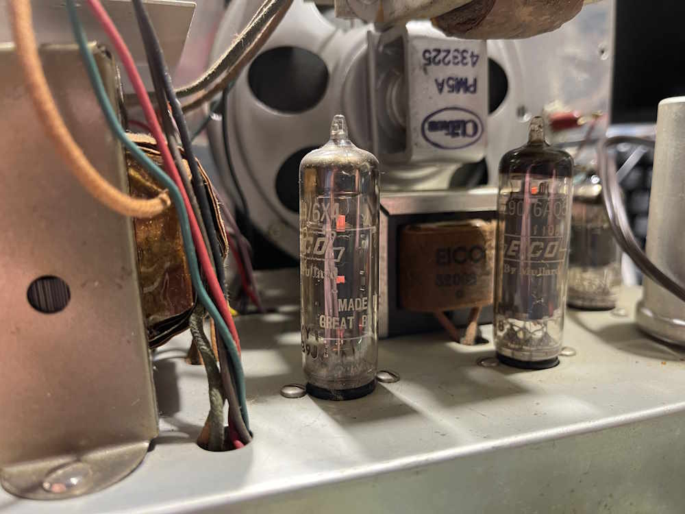
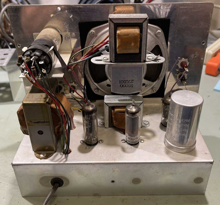
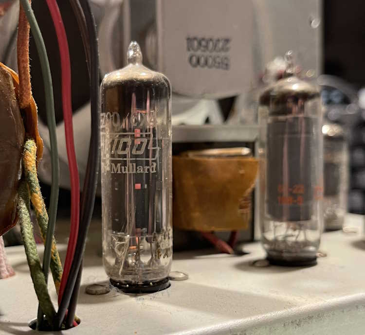
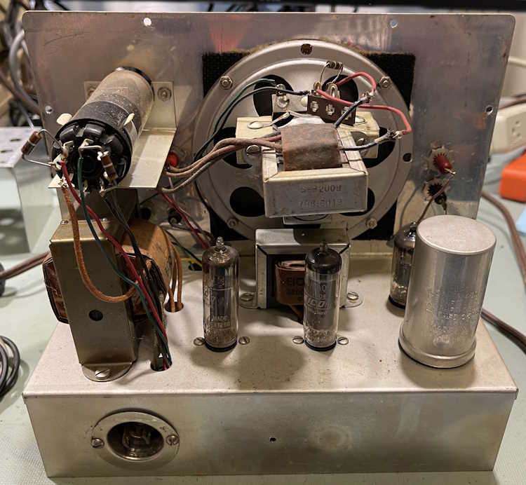
The inside of the unit is equally clean. Tube lineup is two original EICO branded tubes, along with a GE tube in the 6AQ5 position. As this is the power output, it was probably the first to go. Also of note here is the choke wrapping - it’s peeling away, but that’s not a big deal as that’s just the outer wrapper.
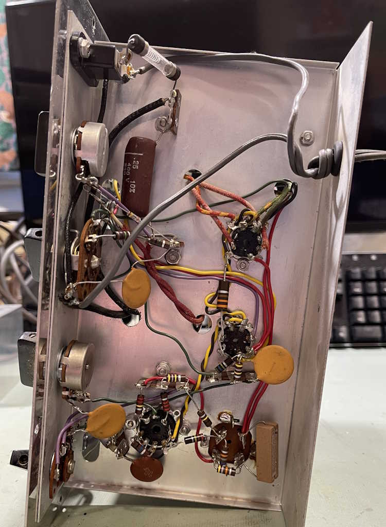
This one may have been a factory build, or a good kit builder. The bottom layout is fairly clean and everything is well soldered.
Everything here is all disc capacitors save the big molded near the top, and of course the electrolytic. So, does it work?
Sure does. The eye is even in pretty good shape. It’s fairly bright and has a defined shadow.
I let this one run for a while, it seems to be in great shape for the age. The filter didn’t get warm, it’s got ample gain, and everything seems to be in order. The resistors are probably somewhat out of tolerance, so I’ll measure them at some point and see what else would need replaced to bring this up to service use.
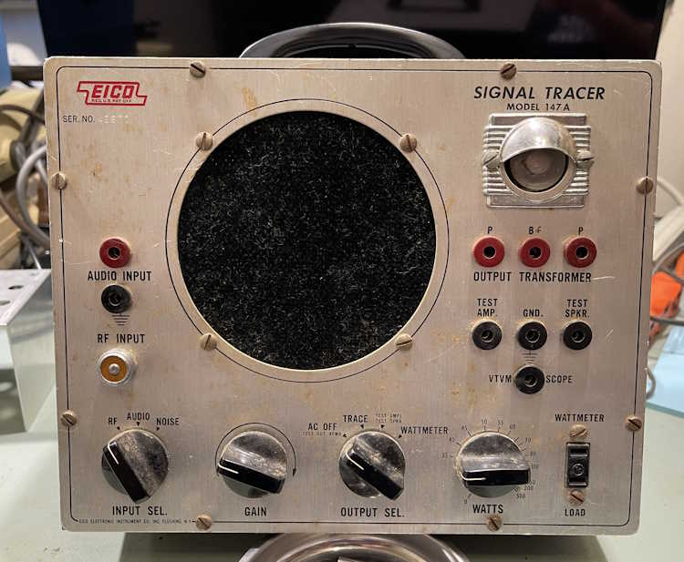
On to the second unit. This one is dirty, and looks like it might be a smoker’s choice. That brown glaze on the front gives it away, although there’s not a lot of any kind of smell on it.
The cabinet on this one is a bit rougher inside and out. Some of the rubber feet are laying inside.
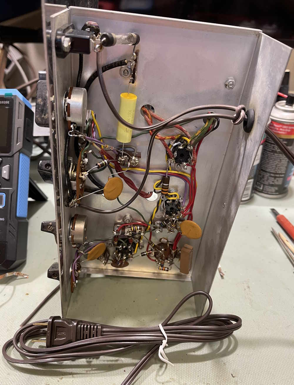
The back has a modification - a previous owner installed a mini Hubbel twist-lock plug and socket. The cord is a polarized SPT-3 unit, so the last time this was touched was probably sometime in the late 70s or early 80s. They did a decent job of the mod, so no real tears shed here. I hate to see chassis and cabinet drilled out like this, but it’s from a past owner so there’s nothing I can do with it.
This unit had a mess of cables stuck in the handle, including a cable with that ever-popular RF connector attached to it.
They’re all in just this side of ready to crumble condition. They’re connectors for reuse, not useful cables right now.
Top of the chassis is cleaner than the outside would lead you to believe. The getter on the 6AQ5 is black, this thing has some hours on it.
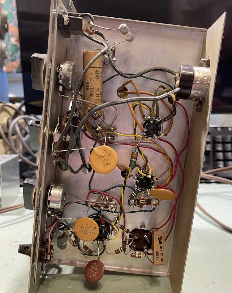
But the bottom definitely shows this one was a kit. The layout is very loose, wires everywhere. It doesn’t look anywhere near as good as the other unit.
So, does this one work?
Yep, it does. It’s hot and has good gain, like the other unit. The eye on this one, however, is very weak and doesn’t have a well defined anything. I could just barely see the shadow, but the camera almost smears it out of existence. This one definitely saw some use, and was probably just left on all the time. While it works, it’s probably going to go on the shelf as a spare or a later rebuild. I do have some new eyes, so who knows where this one will end up.
In all, I think this was a great purchase (even if I didn’t need it!) and it helps the museum with a bit of funds and, as the curator on duty Saturday said: “less things I have to move!”
Stay tuned, the cleaner unit is going to get some touch-up in the next few months.
One of the things that has been suggested to me is a quick way to find all of the major projects that have appeared on this blog. The easiest way for me to do this would be as you see it here: a single post, similar to hamfest pictures, that collects all of the major device projects that have appeared here.
This hub contains all the the things I am currently working on, or have completed. New projects that are still underway generally appear at the bottom of the post, and the post will grow as more are added. The only things that are not here is a few small things that I did for other people, or the home automation stuff. You can find the latter in a new category on the sidebar aptly labeled “Automation”.
There’s a permanent link on the sidebar that will bring you directly to this hub post.
Click on the title of each item to be taken to that project’s hub.
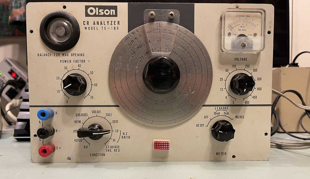
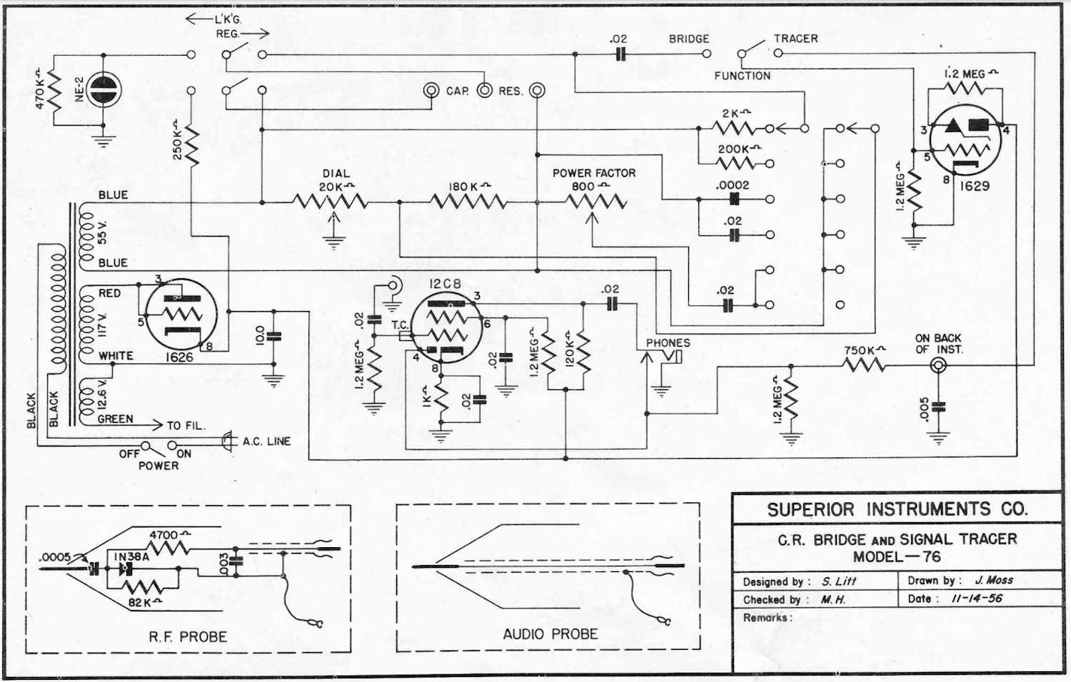
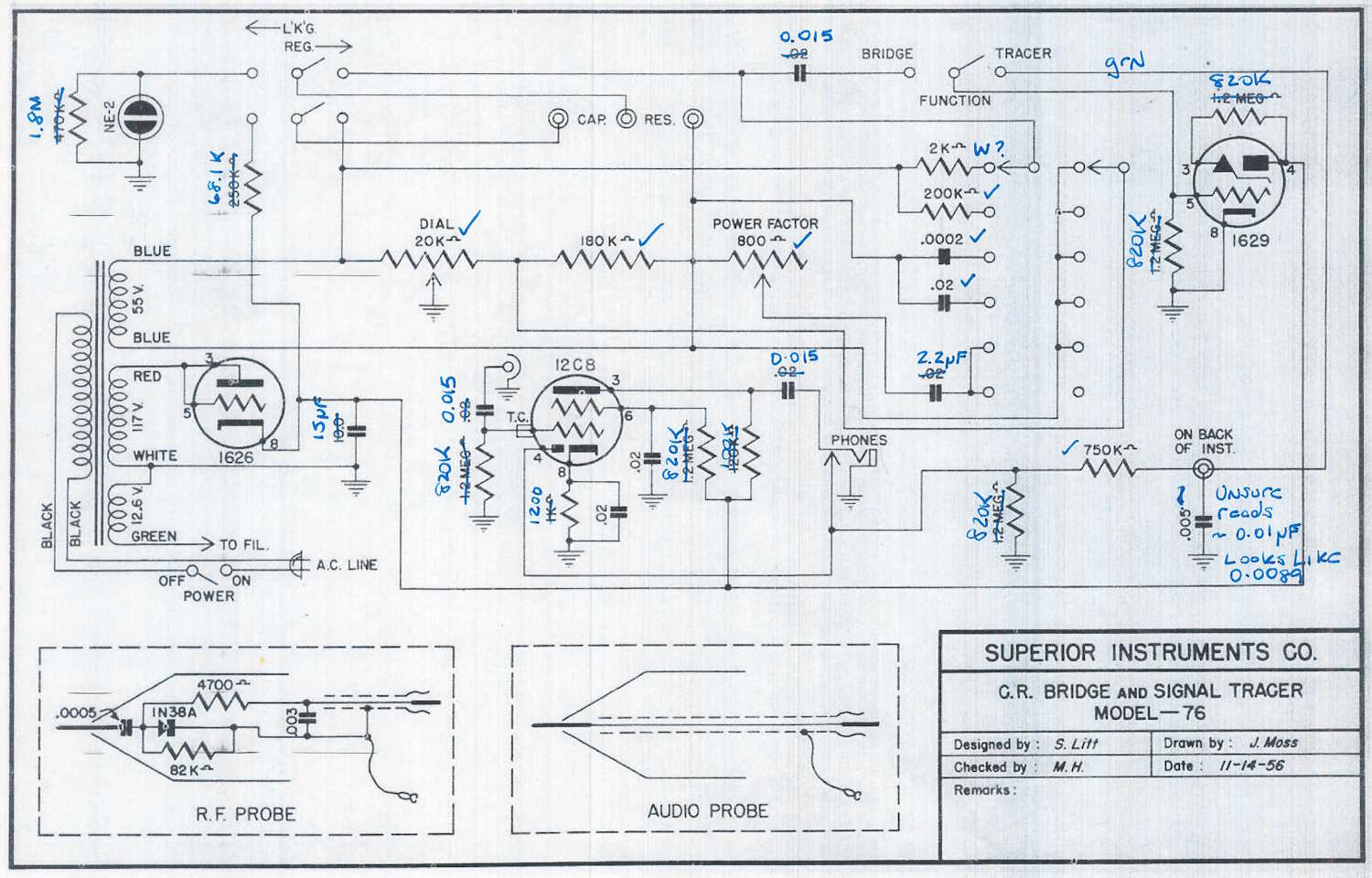
The Superior Instruments Co. Model 76 is an interesting piece, and appears to have been built out of whatever the manufacturer could find at the time. Considering this piece was designed about 10 years after the end of the war, the amount of surplus parts would have been quite high. The schematic that was published and what’s actually in the box don’t match one another.
Here’s what the schematic claims is in the box:
A check of what’s actually in the box:
There’s a lot of different types of components in here. Some RN-type mil-qualified resistors sit beside the cheapest of carbon composite parts. Early ceramic capacitors run with oddball metal can parts, which sit beside devices that have really strange values. The device even uses a low-power RF Triode as it’s rectifier tube.
While this device won’t be difficult to make work again, it’s going to be much easier now that I know what’s inside this thing.
Next part will be getting an order together for parts. Stay tuned!
I’ve always wanted to have some of the switches in my home addressable by some sort of remote control system. For the longest time, that meant using an X10 device, or some exotic home control units that often times cost a lot and/or required some intensive rewiring that I simply wasn’t willing to undertake.
Enter Shelly devices.
These little modules do pretty much everything I had wanted. They’re small enough to fit into most current electrical boxes (older homes like mine will still require some rework.) They offer power monitoring, as well as local switching capability - that is, you can still use the lightswitch that is currently there. They’re also cheap. Under $20 per, even less if you don’t mind an older generation that doesn’t offer 50 million ways to connect.
These are primarily WiFi devices. The newest generation offers Matter control, but they have a local UI that you can talk to. Shelly provides an application that you can run. Or, you can do as in my case - connect them to Home Assistant, as Shelly devices are a platinum-tier supported system.
To get started, I added the Shelly integration to Home Assistant. I did this some time ago when I was playing with a switch unit, so it was already there for this install. That’s a simple matter of adding it like any other integration within Home Assistant.
First thing I like to do it power them up with a cord I’ve made for this purpose and connect to the WiFi UI on the device. This is a local AP, unprotected, and sits at 192.168.33.1. When powered, you’ll see a new AP with “shelly” in the name. Connect, go to the above address once your device has negotiated everything, and you’re in the UI. I then set the WiFi to connect to my network, rebooted the device, and went back in with the new IP address and disabled the local access point. (Home Assistant will warn you about this if you don’t turn that off.) The Shelly integration then found the devices and automagically added it.
Past that, it was a simple matter of creating dashboard panels and automations like any other device.
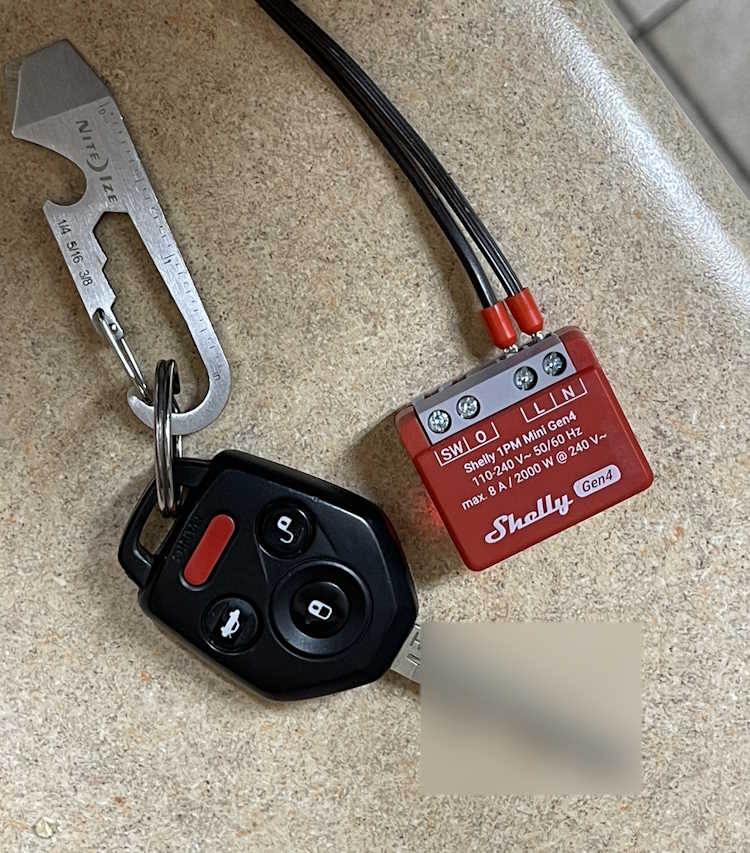
I used two different devices this round:
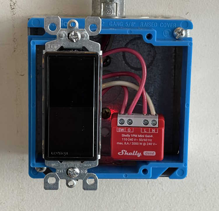
This is called the Shelly 1PM Mini Gen4. (Yeah, they need to work on those names.) It offers both remote switching capability via WIFi, and local switching capability via the “SW” terminal - you simply input the switched line voltage from the original toggle and it takes care of the rest. Other than a slight delay in switching, you notice nothing.
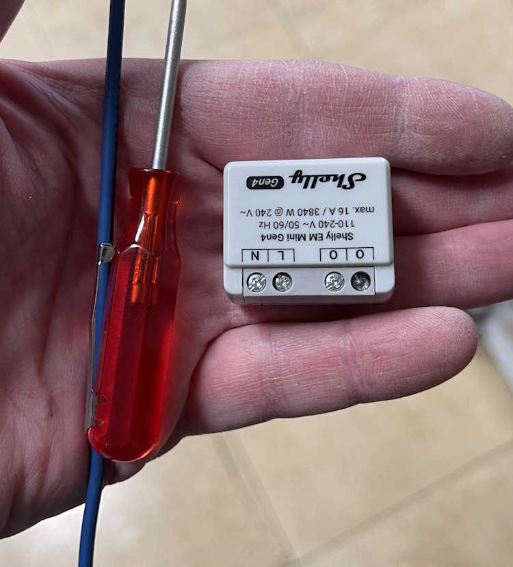
This device is similar, but offers a higher current capacity without any switching capability. I’m installing one of these in an outlet connected to my clothes washer. It connects the same way, just give it power and set up WiFi. The two “O” terminals are the line outputs, you use a single neutral connection which doesn’t pass through so you’ll need to jumper from the neutral line to this device. This is similar for their entire offering.
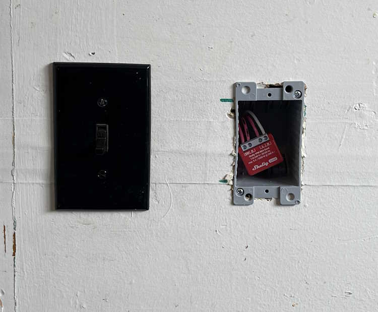
First one is the “Back Porch” lamp. That’s just a wall sconce with a bulb, like any other outdoor lamp you’d have near a door. Boxes in my home are old, small, metal, and cramped. Mounting nails go through the box into the stud, which reduces available space even more.
I decided to mount a new box next to it, just for the Shelly device. Cable was jumped and clamed to the device, and it got covered with a blank plate. Easy in, and can be changed without issue.
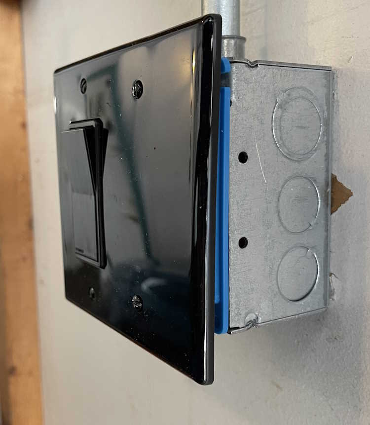
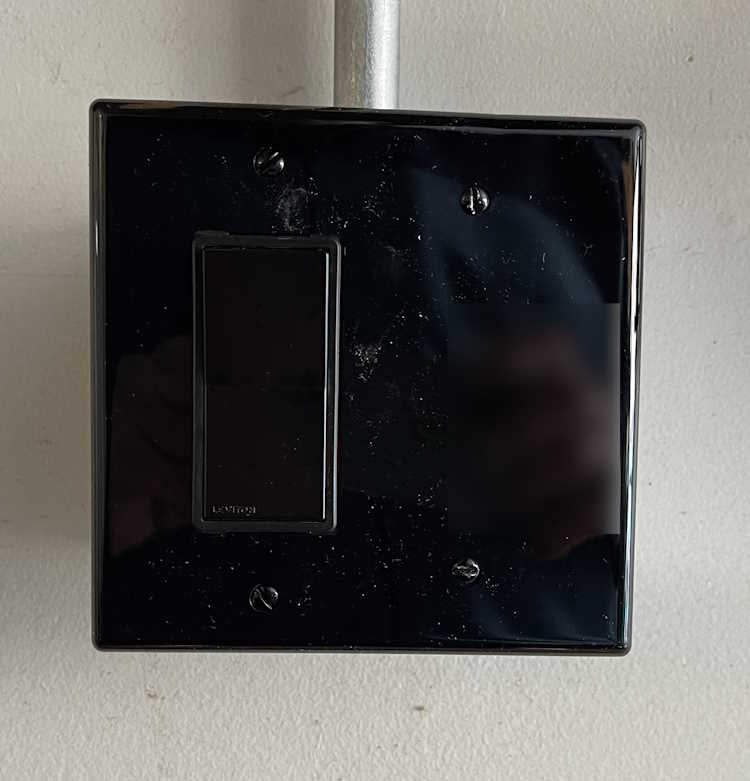
The second PM1 went into a lamp in the garage itself. This is just a wall lamp I put in for some extra light. It’s scheduled to come on and go off at certain times when I have a high probability of being in the garage. This is an on-wall piece of conduit, with a metal box. It originally had a metal plate, so I removed that and replaced with a plastic mud ring and cover. A Decora switch was used because that’s the kind of plate I could get at the time. Like the other unit, this one simply sits to the side of the switch, It faces my local AP, so there’s no signal issue with the metal behind it. You’d never know there was something inside…
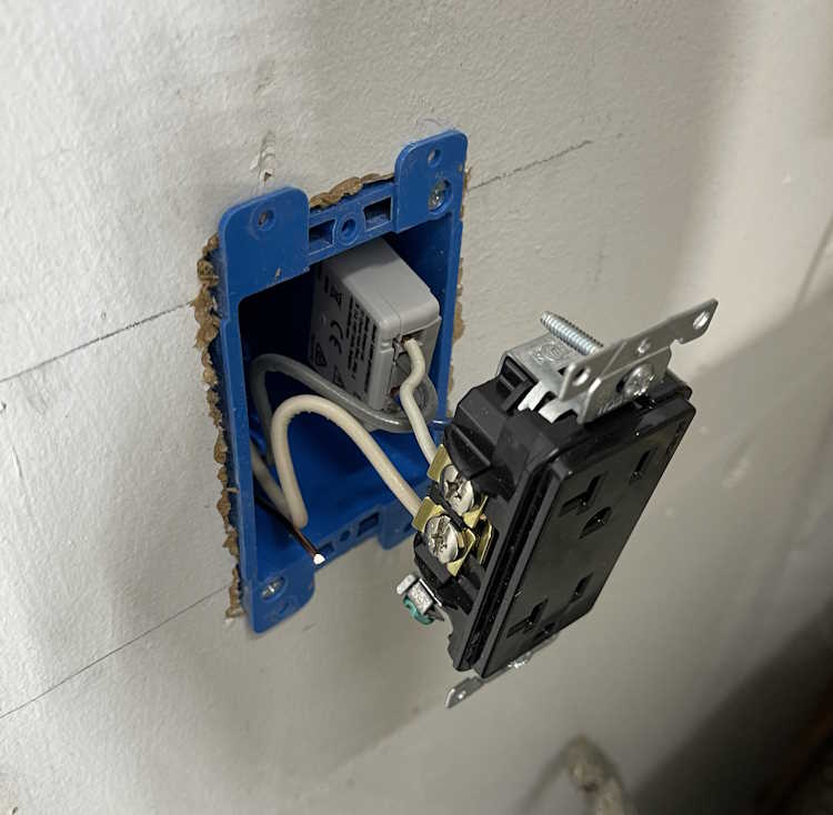
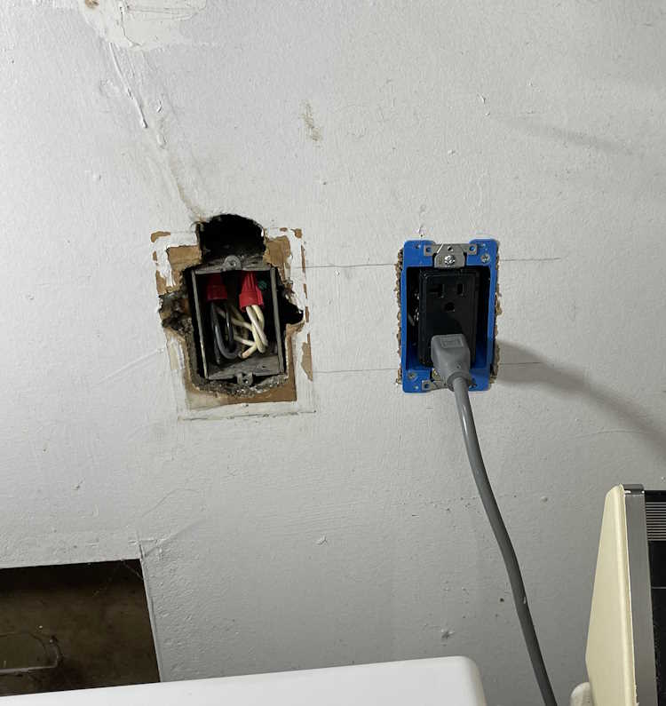
The third one for this install was the monitor-only device for the clothes washer. Again, this was a small metal box, and had a lot of wire in it. I took the opportunity to mount a new box next to it, run some fresh cable, and make the connected in the new box. The EM was attached to the back of the duplex, and simply slides into the box. I left enough cable that this can just pull out if need be, and the device is right there.
The screw terminals on these are just big enough to take a solid 12 AWG wire. Anything larger won’t fit.
This one looks messy because the previous owner just broke into this box and ran a wire upstairs for an AC unit. You can still see where that was on the wall, and is evidenced by the big hole above the box. This line feeds the washer, and some of the kitchen - fortunately they did pick a 20A circuit, but it wasn’t rated for continuous use + kitchen gadgets. I took the time to tidy up the connection so it wasn’t overly cramped in the box.
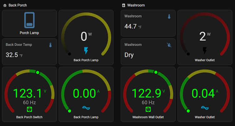
So…what does that look like in Home Assistant? That depends on how you set it up, but this is what I have:
The lights all have switches. The monitor-only just has outputs because there’s nothing to switch. So far, it’s worked quite well and all automations I’ve set up have fired flawlessly.
So what’s the takeaway here? I’d consider these devices to be in the “experienced” category if you have the electrical system in your home that’s able to handle the extra size capacity, or “advanced” if you need to do what I did. They aren’t a beginner thing, but their operation is exactly what you want - quiet, unobtrusive, and full of all kinds of good information.
I’m going to be installing a few more of these devices before I’m finished.