A Korg 6P1 “Nutube” kit, part 2: Let’s test the kit.
Wednesday, June 10, 2026 at 06:40:31
This isn’t a comprehensive test, it’s just a “does it work?” thing. And it does.
The kit assembled quite easily, but you should definitely pull a schematic from the vendor’s site because there’s no indications of values on the board.
I did have two issues with assembly, both of them my fault:
1: I put a capacitor in backwards, took it out, put it back in the same way, and destroyed a pad in the process of removing and replacing it once more.
2: I started to install a resistor in the wrong place because I took the part identifier to be pointing to an area it wasn’t.
Neither of these is the vendor’s fault, and I blame my not stopping for a break for the first one. Always take breaks when building something like this.
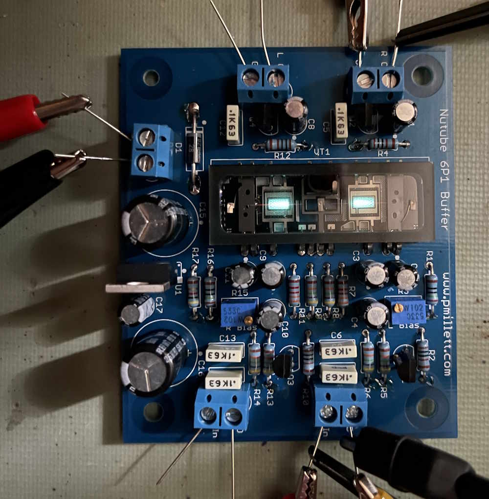
But, the kit turned out ok:

Parts were purchased from mouser, with some (the screw terminals) coming from my own stock. As the BOM the vendor provides has a lot of obsolete parts, I created a new one:

Note this does not include the screw terminals, which I had in stock. See the references section for a this document and the schematic.
I’m using 12V from my bench supply to power it:
It seems to be drawing about 62mA.

Signal output is, of course, inverted from the input because that’s how amplifiers work. Here’s the output (yellow) vs. input (magenta):
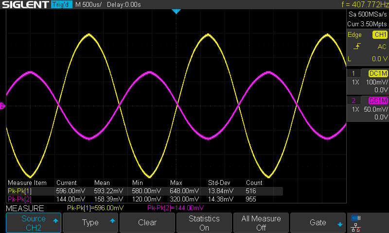
Gain in this configuration is ~4. A bit more than a buffer, but fine for low-level signals.
It works, and there were no real issues with assembly. What am I going to do with it? No idea. It may end up as just a small signal amp on the bench, I’m not really sure. Stay tuned!
References
Schematic and BOM: https://wereboar.com … 0Kit%20Documents.zip
Vendor site: http://pmillett.com/ (note: http:// only)
Youtube videos on this item: Coming soon.
Previous part of this series: https://wereboar.com … ets-look-at-the-kit/