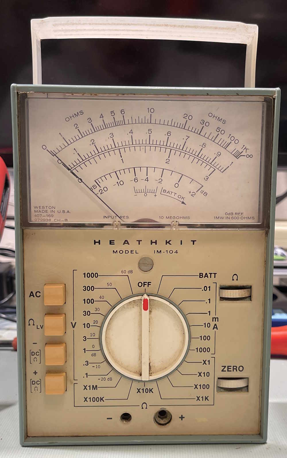
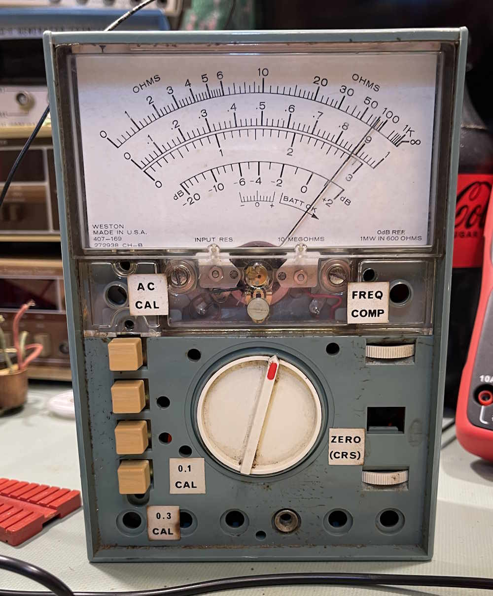
I picked this device up at the Cuyahoga Falls Hamfest this year. In my quest to not bring home any more metering equipment, I brought home only three this year - a Keithly microvolt meter, a generic Heathkit tube device, and this one. I’m not sure, but this is probably one of - if not the first - of Heath’s FET driven meters.
It was sold as not working. Well…these had a tendency to lose the FET in the front end, so…yeah. We’ll get there.
What’s so special about this? A VTVM presents a high-impedance load to a circuit. That is, there’s very little load from the meter itself so you don’t disturb your circuit. Meters like the Simpson 260, on the other hand, simply drive the meter movement from your measured voltage. This presents a lot of load, and can change the value of measurements in a circuit with small signals. The FET meter attempts to rectify both of the previous devices by presenting a high impedance AND a low current requirement, giving you a portable instrument that does the same thing a current-hungry VTVM does.
However, none of that matters if it doesn’t work. Let’s check it out:
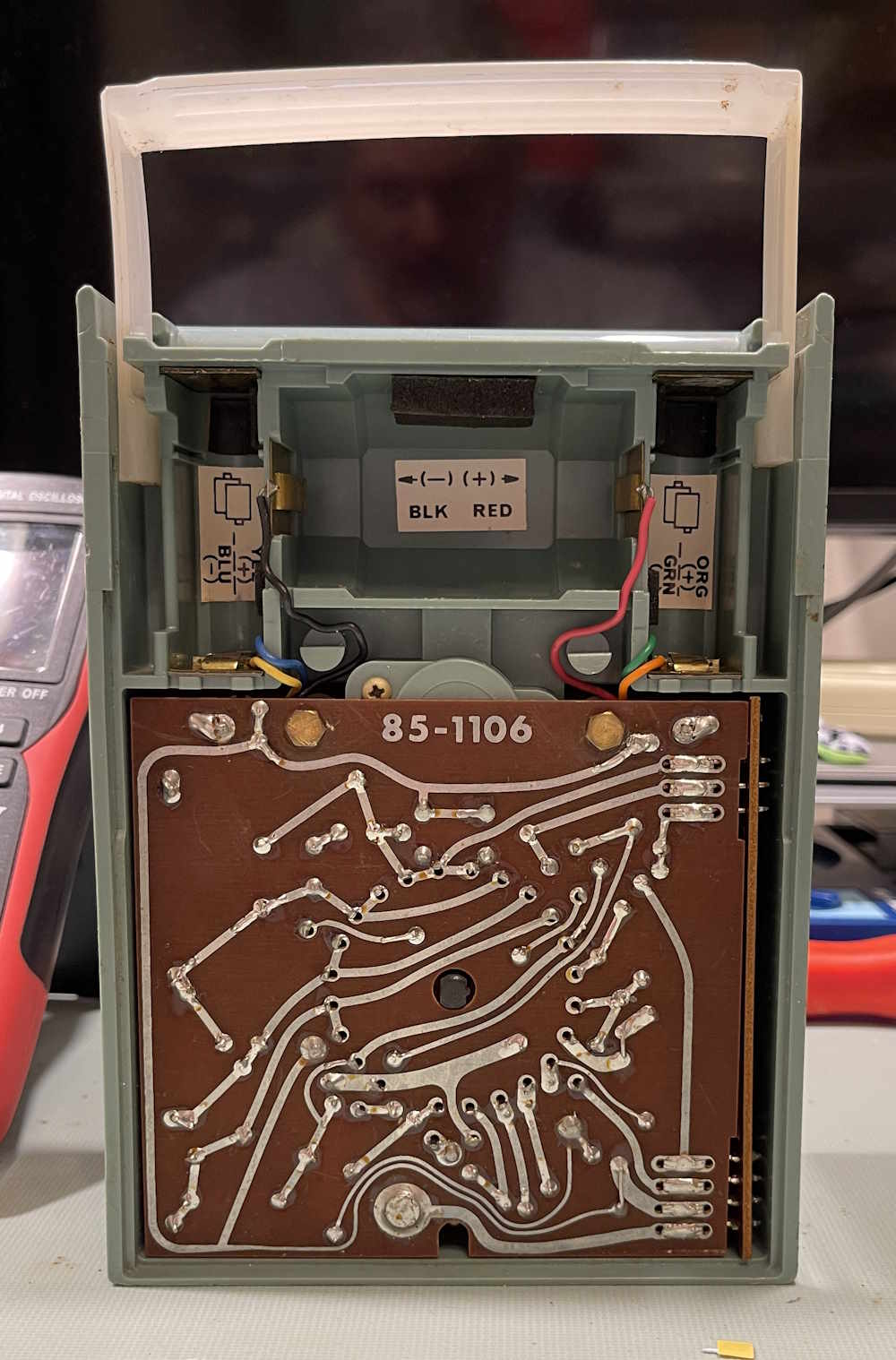
The back comes off in a fiddly manner, you unscrew a big screw and kind of lift the bottom of the back while attempting to pull the back towards you and slide it out of it’s slots. This has the effect of needing 3 1/2 hands, but eventually I removed the back. Inside is compact:
I can immediately see there are multiple layers in here. It feels firmly held in…by something. But first, the batteries. This thing needs 1 D cell for the ohms, and 4 AA cells for the measurement circuit. It’s run in a split configuration to drive an op-amp, so you have +3 / -3 VDC. The battery contacts are somwhat corroded, however.
Fortunately, it had carbon-zinc cells. These cause localized damage that can easily be removed with some scotchbrite and cleaner. This type of damage can cause rust to steel parts when it’s in contact with them, but is usually just where the battery is. This is unlike alkaline (and old mercury) which will outgas and cause everything to turn a shade of green before turning a shade of “open wires.”
Install some batteries, and…nothing happens. Chances are it’s a very dirty switch, but let’s get it apart and check that FET.
How do you get this thing open? Well, that’s an adventure in itself. I’d suggest grabbing the manual and reading it, because there’s some involved steps to dismounting the board. You can grab a copy from my documents library, or from WR5KL, who graciously hosts it. Links are at the bottom of the page.
Since it’s a pain to get open, I’m not going to cover that. Read the manual. I will say that I got it apart a different (wrong) way, so it’s somewhat robust. Somewhat. Just do not try and pull the knob off. It does not come off, and does not impede the assembly of the unit.
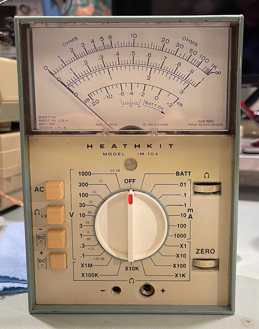
The Heathkit IM-104 Assembly
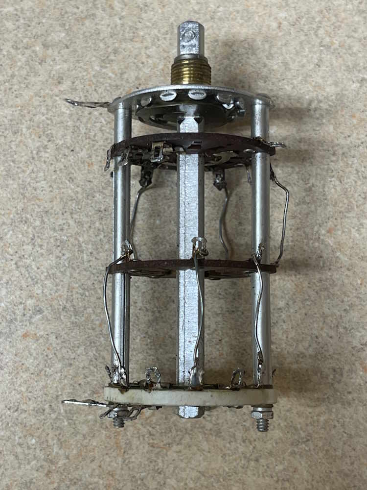
Once the unit is apart, we have the main assembly. There are three boards, a top board with the active components, a lower board with some passives, and a side function assembly. This pulls apart easily.
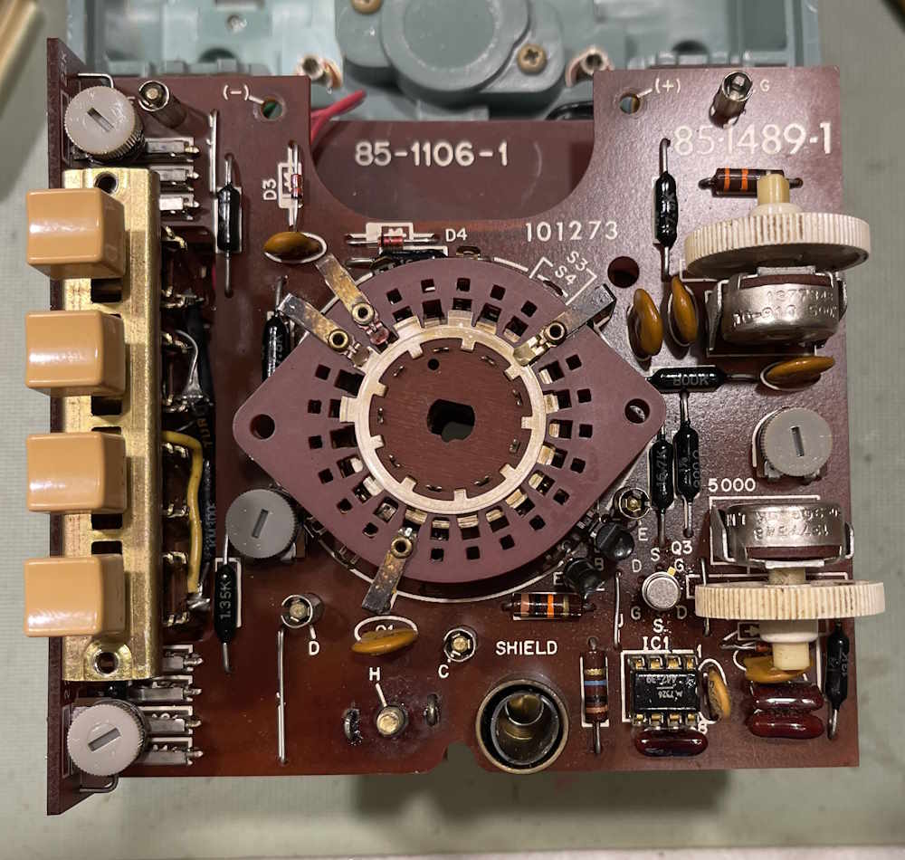
Remove the side function assembly by working it off. It’s connected with 4 sets of prongs that go into mating connectors on the side of the boards. Essentially, this is one of those big amphenol pinned connectors without the white housing. Set that aside.
The main assembly consists of two boards. The top has two range switch layers, and all of the active components. The FET, a special dual instrumentation device, is the metal can in the lower right corner, just above an IC. The IC is an old Motorola part, and is generally the equivalent of an LM301. The rest is some glue and passives to drive the assembly. The zero and ohms pots also live here.
This lifts off of 5 brass pegs that go through the board.
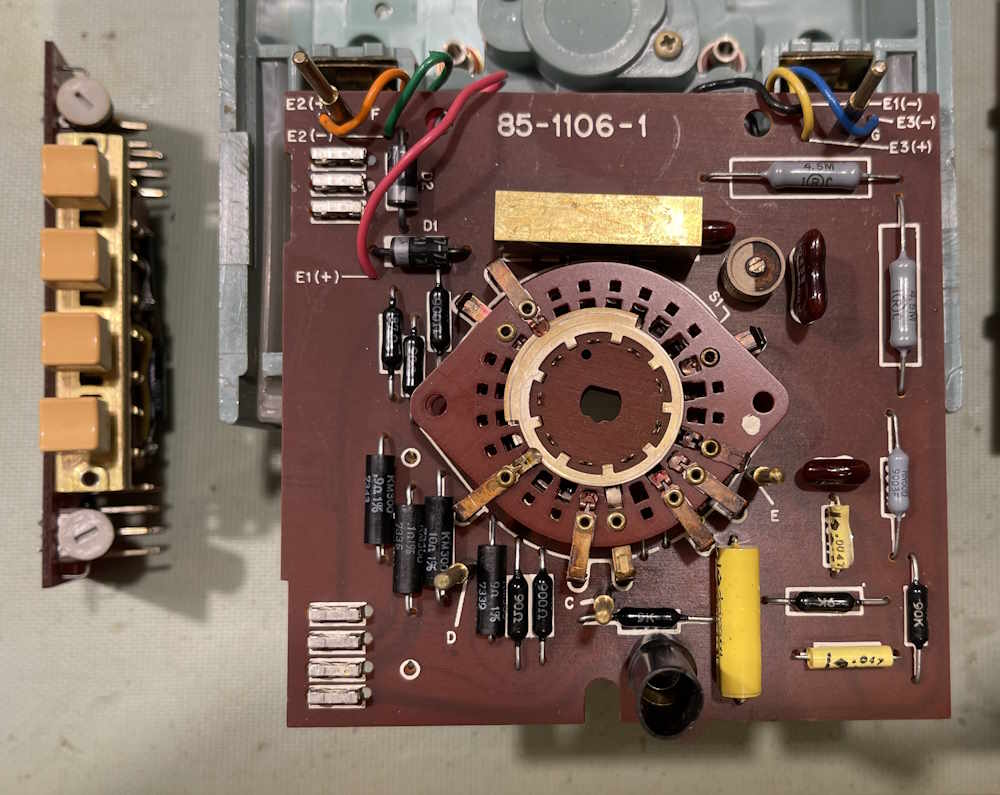
The bottom consists of two more range switch layers, and a bunch of passives for the ranges.
All of the range switch wafers float freely, and are chained together with a ridge on the center post. Remember that when reassembling, you’ll need to manually align the wafers to have it slide on, unless you’re lucky enough that the post pulled out with the removal.
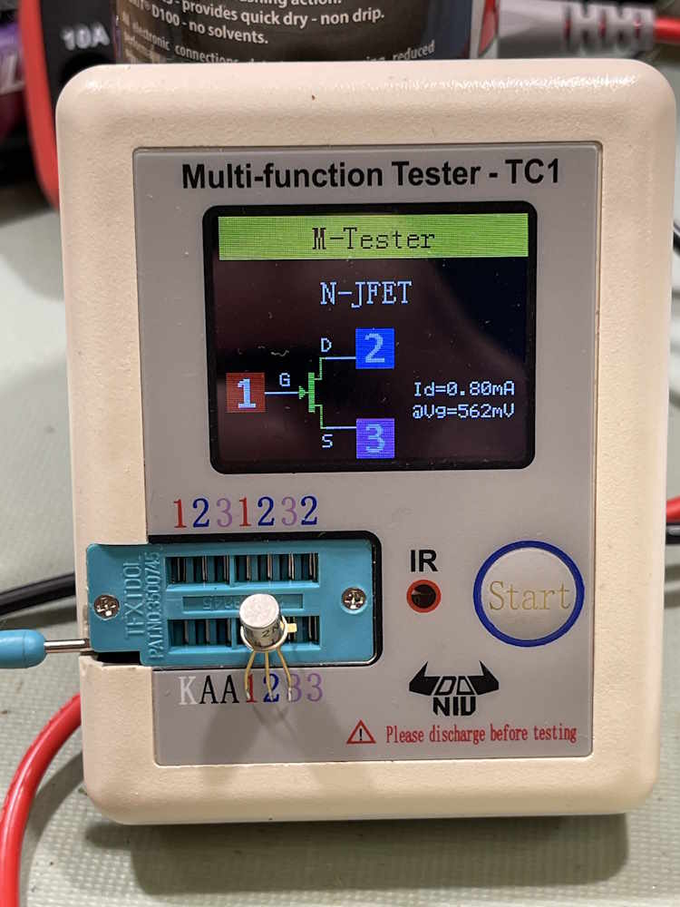
How about that FET?
This is a single sided board, and the part was easy to remove and check. I was able to desolder quickly with braid and put the FET in my M-Tester. It’s good.
Both sides of the device measured as a FET. It got soldered back in. That means the range switch is probably just so dirty it’s not making contact. I was able to clean the tops of each layer and spray the bottom. That got us back to some semblance of operation:
The switch is still very touchy, however. I decide to liberally dose the switches with Deoxit and let it set for a while.
A week later, and it’s working.
The switch is no longer touchy, and the meter is decently accurate. Alright! It’s still going to need a good cleaning of all wafers, but I can order some thin, flat swabs for that. Later, of course.
Some removal of dirt, and reassembly. It’s a nice looking piece with that weird instrument blue and those UV colored switches. In all, a pretty good purchase for the few bucks it cost.
I’ll probably do a complete cleaning on this later. Stay tuned:
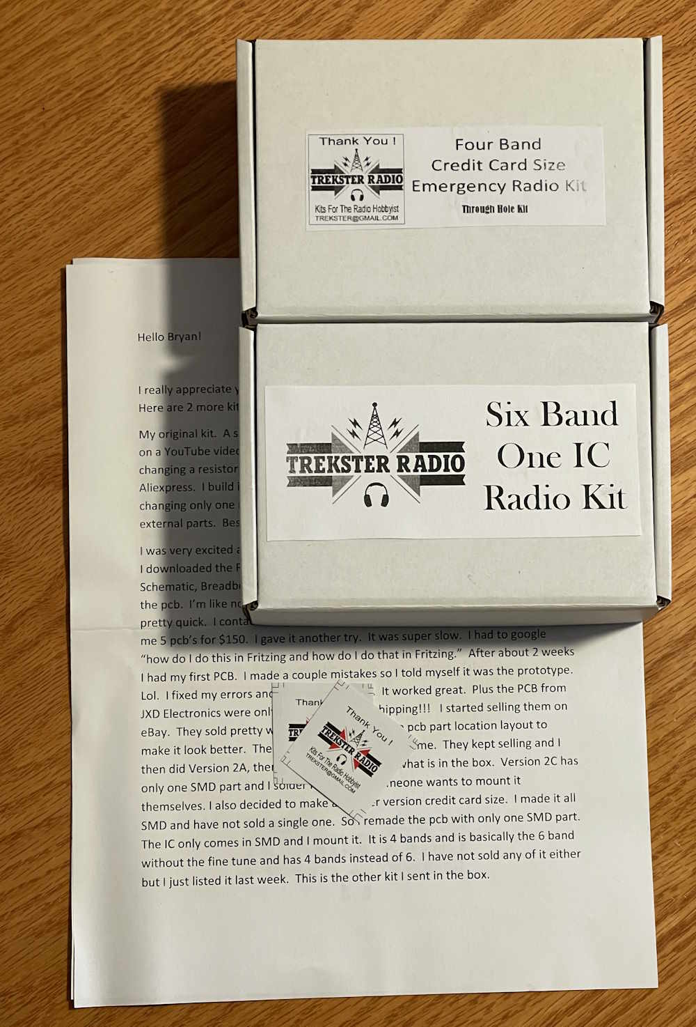
I feel it necessary to mention that these kits were offered to me with no cost, in exchange for a review.
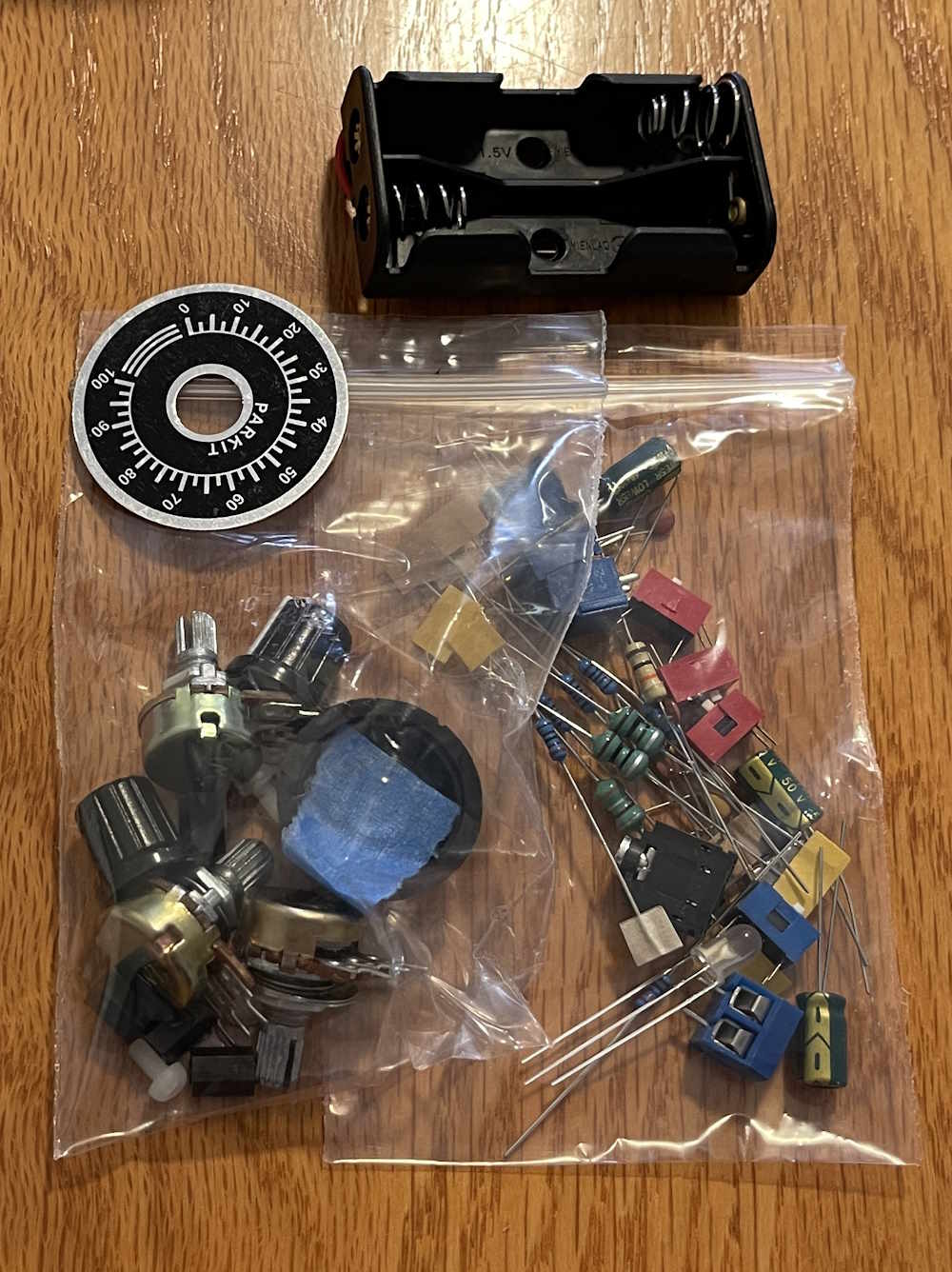
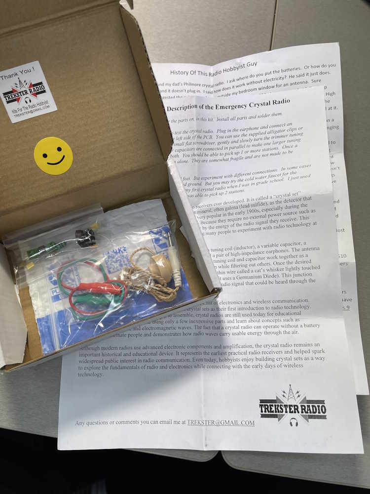
After the Trekster Crystal Radio Kit post, the creator asked if I’d like to review a couple of his other kits. Of course, I love kits, especially ones that actually do something - and a radio is the best “does something” you can have. There are two kits in this package, a 4 band and a 6 band kit. Each is packed in it’s own labeled box, along with some notes from the creator and stickers. Stickers in a pack is always cool, and these will probably end up on the network rack somewhere.
Let’s start with the four band kit first. The creator has stated that he envisions this as a device you can keep around in the event of an emergency - be it a simple power outage, or something far more damaging. Because of that, the size was kept to a minimum. So what’s inside?
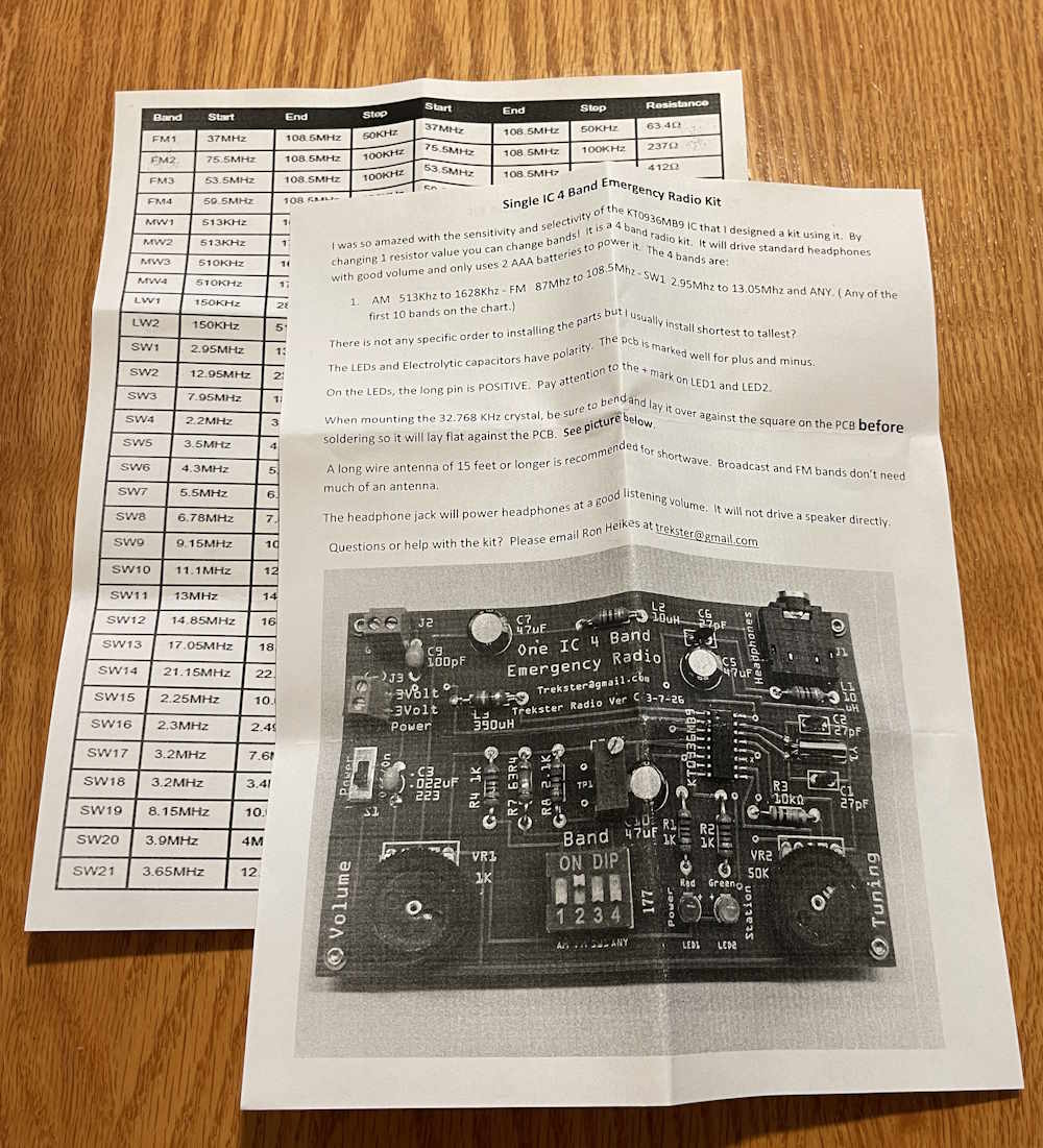
Some paperwork, including some kit assembly notes and a sheet detailing what resistances are for what band.
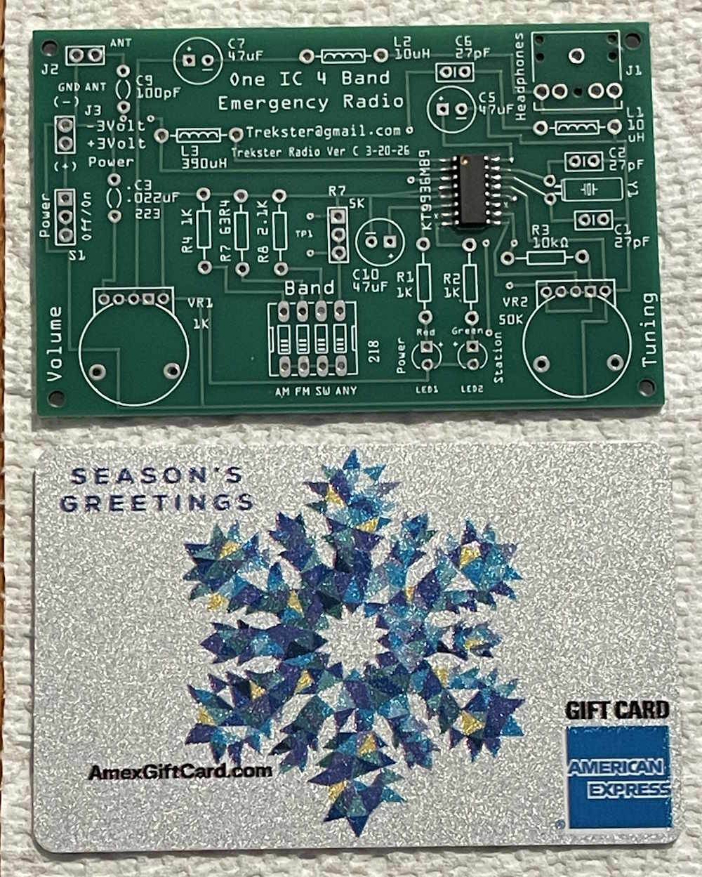
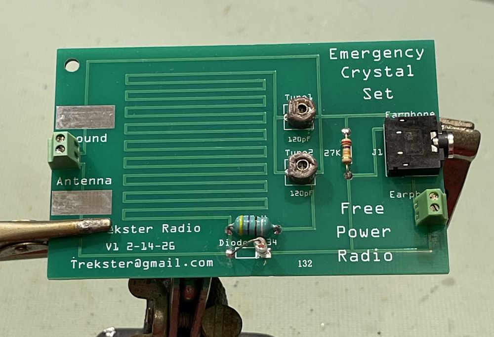
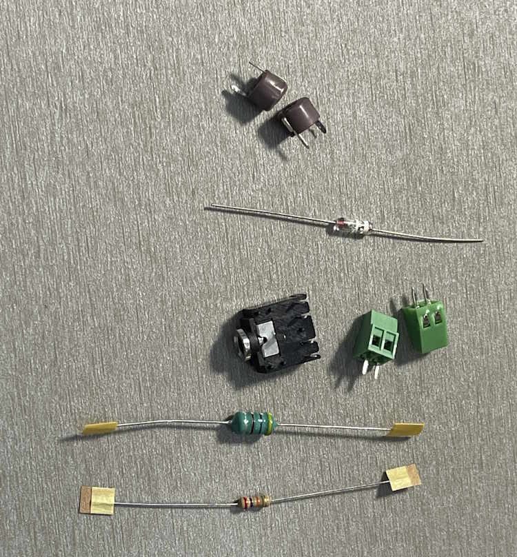
There’s a nice PCB, and yes - it’s credit card sized.
The creator has soldered the main IC on to the board for you ahead of time, although you can request that this not be done. SMT soldering can be a bit tricky, so this is a very nice touch, especially for beginner kit builders.
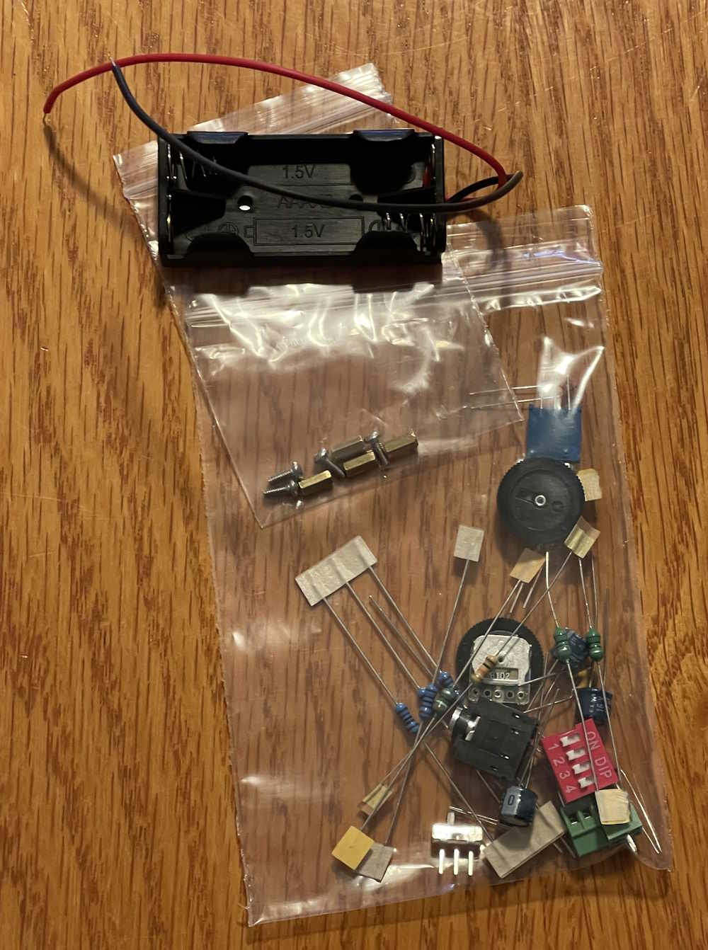
And of course, parts. You need parts. This is a fairly small amount of parts, so this would be a very easy kit for someone looking to do their next build.
Note the battery holder. This guy runs on 3VDC provided, in this case, by two AAA primary (not-rechargable) cells. Why is that important? You may not have power in an outage or other emergency, so something you can just shove some batteries in is an imperative. You can probably get batteries, can you get a charger for that unusual cell in your other device? 3V is also a nice, easy voltage to get - if you have LiFePO4 cells available, a single cell with a Ge diode in series will give you ~3V when charged, and there are plenty of other ways to get that small of a voltage in the event you can’t get it from regular alkaline cells. This is a kit, don’t be afraid to experiment!
The Six Band unit is similar to it’s little brother, save it offers…6 bands! This one also comes with the main IC soldered, or not depending on how you request it. There’s also some instructions and a band selection sheet inside the box. The PCB has grown a bit to accommodate the extra components for more bands.
This one comes with quite a few parts. I’d probably put this in the “Just past beginner” level. Note that it also runs off primary cells, but in this case we’re using AA batteries. The above notes for the 4-band also apply here, don’t be afraid to get 3V from other places.
In conclusion? What can I say, the crystal kit was a solid 10. It did what it was supposed to without fuss, and was easy enough to put together. The board is clean, well marked, and should present no problem to anyone with a little bit of electronics experience under their belt. I don’t expect any problems from these devices.
You will need something to make an antenna with - 50ft of 22ga wire is probably fine, and something to get an Earth ground with - depending on what you’re trying to receive. Those are on you, but really - it’s just wire. Order a spool on eBay and be done with it.
I’m looking forward to putting these together, and I’m going to try and get that done soon. Dayton is coming up, so it may get pushed back just a bit - but I think I may go all out with the “no power” theme and see if I can make this run on a bleach cell battery. As always, if you’d like to get one of your own, you can purchase direct from the creator’s store: https://www.ebay.com/usr/trekster4tw7.
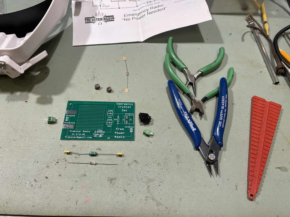
I was going to put this together in a couple weeks, but had some time in-between laundry and lunch this past weekend.
For this build, I used my 35W iron. You probably don’t want to go much lower than 30W, too small and you won’t get a good joint. Size your iron appropriately!
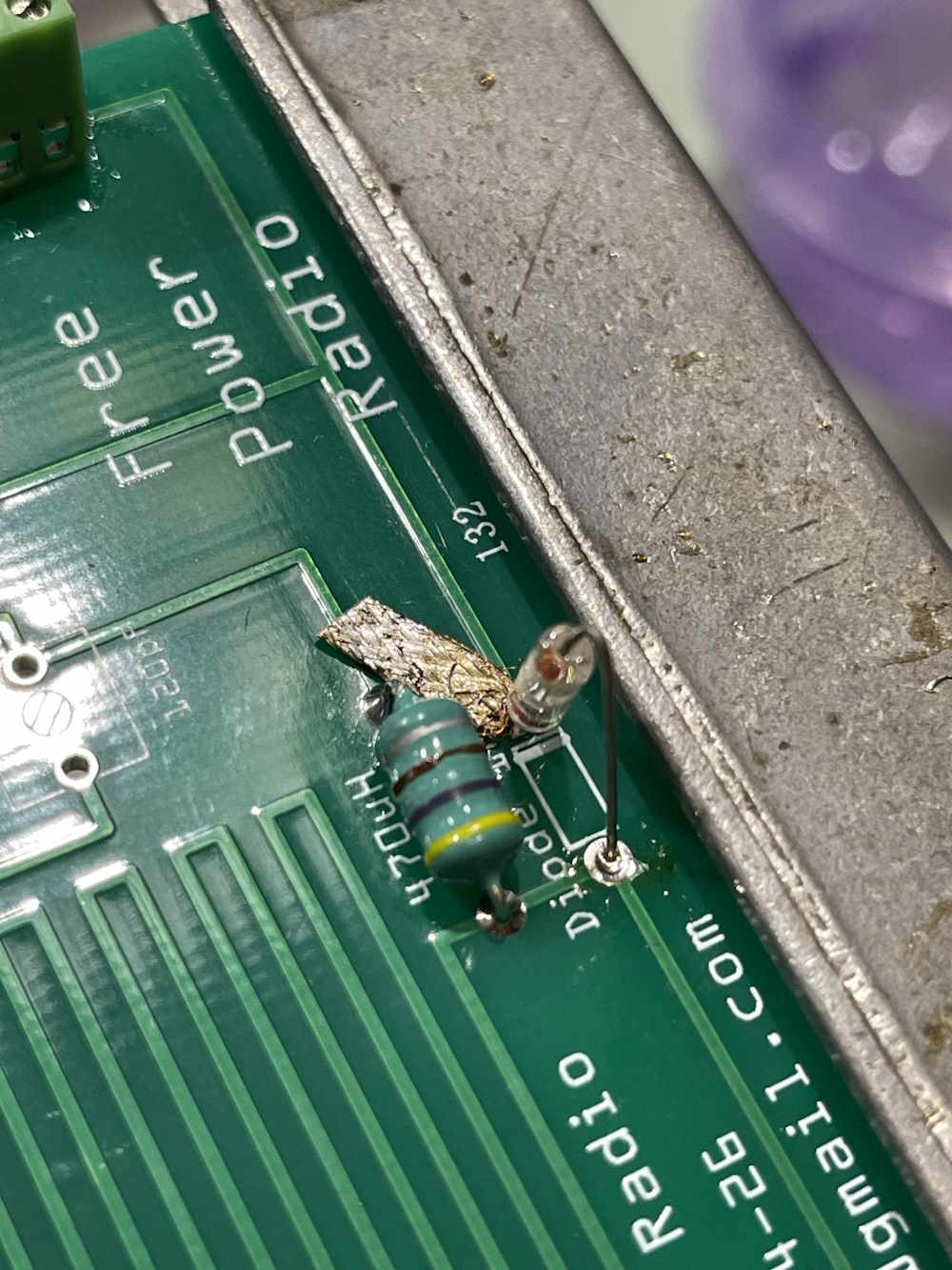
To start, there aren’t really any instructions, per se, with the kit. It’s pretty self explanatory where things go, and most only fit in their own spot. Easy enough…I started with the inductor and resistor:
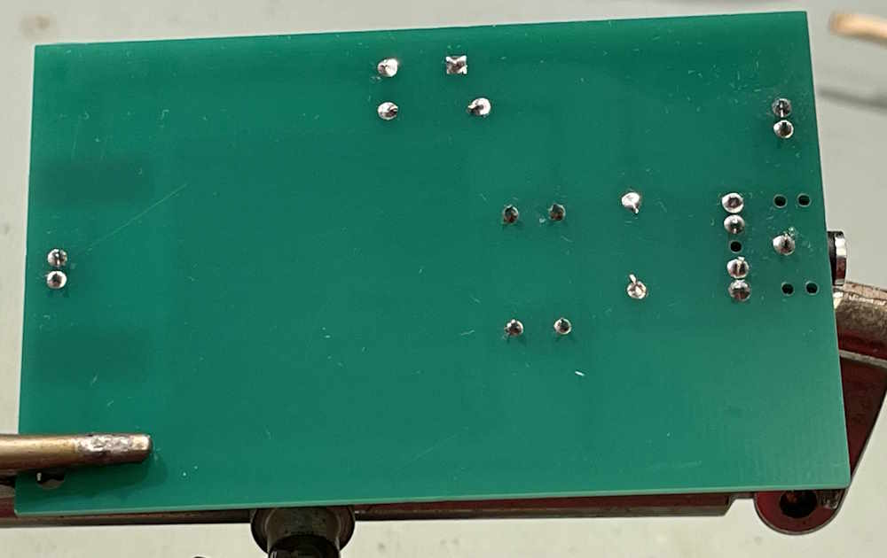
Solder flow-through on the board is excellent, and I was able to get nice fillets on both sides.
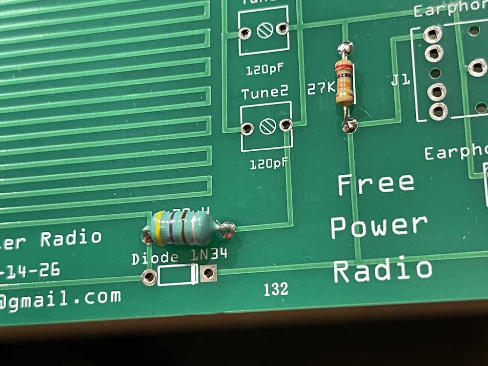
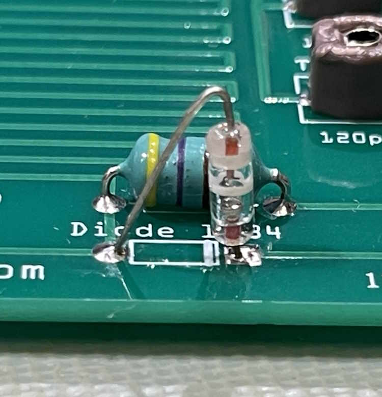
Next was the diode. This kit had a smaller than required footprint, and the kit creator tells me that’s now corrected. However, that doesn’t stop us from installing the part. Simply (gently) grip one end of the diode with pliers or tweezers, and bend one lead over so you get a triangular shape. Then insert in the holes. I used a piece of old solder wick to lift the diode temporarily because I didn’t want the glass body in the fillet, and then just temporarily touched the opposite side with some solder and the iron to tack it in from the top.
After the one lead was tacked in, I turned the board over, soldered the opposite end, and finished the first side.
A note about these diodes, and Soviet diodes in particular:
Germanium diodes are more sensitive to heat than other parts. While not as bad as they were back in the olden times, it’s still good to get in and get out as quickly as possible. I wasn’t terribly worried about a good top fillet here, the bottom is fine and I was quick about it. So…be quick, and be gone. Don’t let your iron linger.
I’ve written a longer post on the differences between USA and Soviet diodes, you can read that here if you would like.
Second, the diode isn’t installed wrong. Soviet diodes put the band on the anode, not the cathode like USA diodes. It looks wrong, but it’s not - if you get a similar (or any other Soviet-era diode,) just remember - bands opposite the markings on the board!
I went ahead and installed the connectors and the headphone jack. If you want to completely wash the board with alcohol to remove flux, now is the time to do it. You don’t want that getting into the capacitors.
Last was the variable capacitors. Those were soldered in and gently cleaned on back so as not to get any flux in the capacitor itself. Note that you’ll need a very thin, small flatblade to turn these. It’s ideal for setting a station and forgetting it.
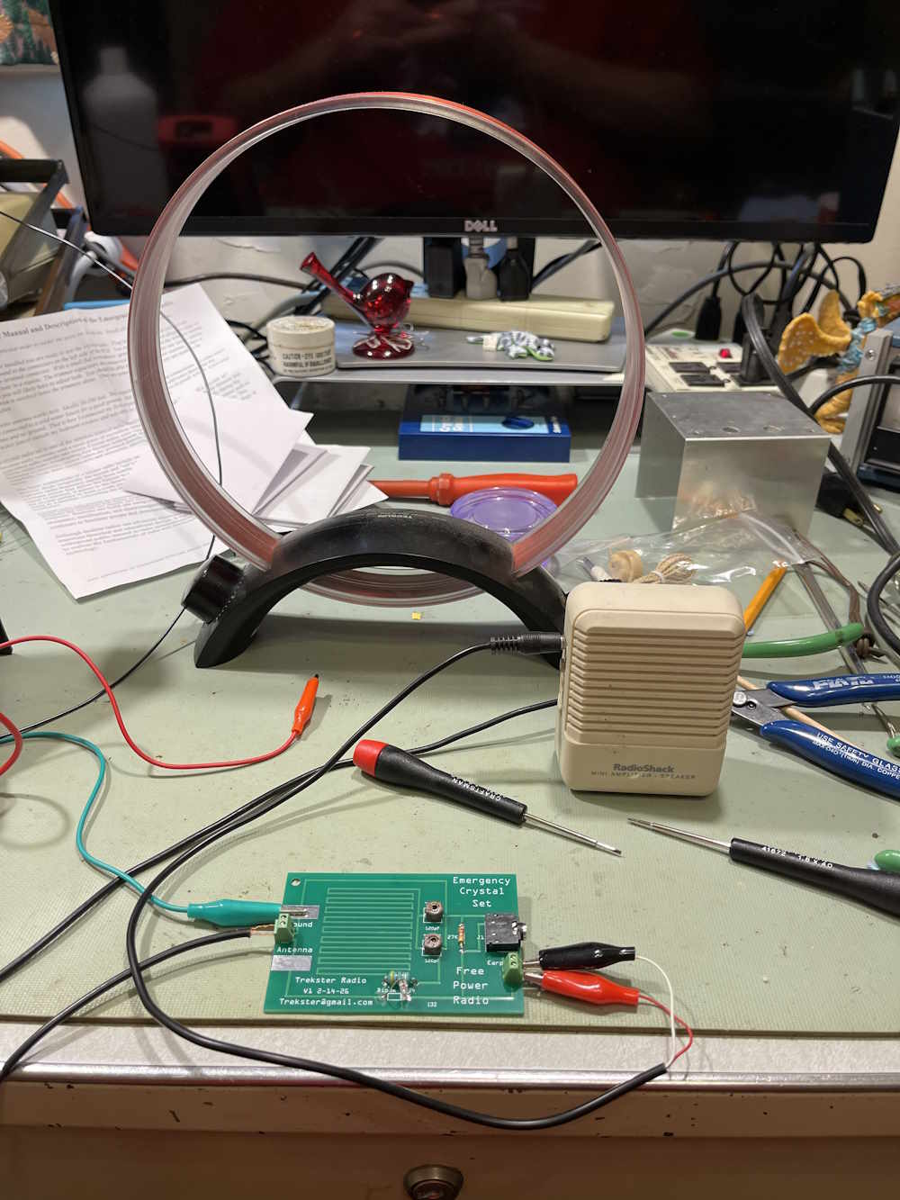
How’s it all look?
How’s it work?
Pretty good, I’m pleased. I mean…a crystal radio can only get you so far, but it performs better than the old Science Fair unit in the background of the image. The only other thing I need to test is a longwire, as my tuned loop well overrides any capacitance on the board itself.
In conclusion, this is a really cool little kit, and crystal radios are a great introduction to both kit building, and to radio itself. These have always fascinated me, and this one is no different.
These require no power, so they’re ideal for emergency preparedness. With standalone radio vanishing from modern homes in favor of phones and streams and computers, having an alternate source of information in the event of some adverse event is really something everyone needs. Pack this up with some long wire for an antenna, some clips to connect to a ground, and a small screwdriver - you have a nice little package to take wherever you want.
Mine is, as soon as I can get some small standoffs, going to be tuned to a station and slipped under the stand on my desk as an always on audio source that has no power connections to interfere with what I’m doing.
Thank you to trekster4tw7 for the excellent communication and feedback. Happy listening!
Link to the eBay store where you can purchase one in the previous post.
Germanium diodes are a staple of electronics. It appears as the detector in both radio and television, the tone chain of musical instrument amp, and plenty of other places. This part offers a low voltage drop, low capacitance, and relatively high speed. They used to be cheap and everywhere, and still have plenty of uses - especially for experimenters.
Unfortunately, germanium diodes aren’t common these days, and aren’t made in any great quantities. There’s also the online hysteria surrounding the part, where unscrupulous sellers are more than happy to label a schottky diode as germanium. While these are fine for detectors in radio, they aren’t germanium and if you’re expecting the properties of germanium, you won’t get it.
However…
The USSR made germanium parts right up until the end. There’s still millions of germanium diodes out there from this era, and, while even those are starting to get harder to get, you can still get them relatively easy from online sellers and auction sites. These diodes are perfectly good germanium parts, and came in many different styles and ratings. For most experimental purposes, there’s no difference between parts, and this isn’t going to discuss that. There is, however, a singular difference between Western and Soviet parts.
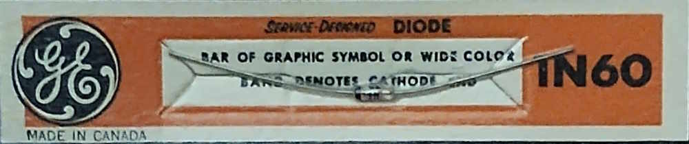
Here’s an old GE 1N60 diode. This image came from…the Internet. Somewhere, I’m sorry I don’t remember where.
Note that the package states the cathode, i.e. negative-most terminal, is denoted by the band, or the bar on the graphic symbol (the diode symbol) printed on the glass. In this case, the cathode is pointed towards the left. This is the way Western diodes are marked, and is the way pretty much every diode made today is marked. There are some exceptions, but there’s almost always some identifier to indicate what’s what.
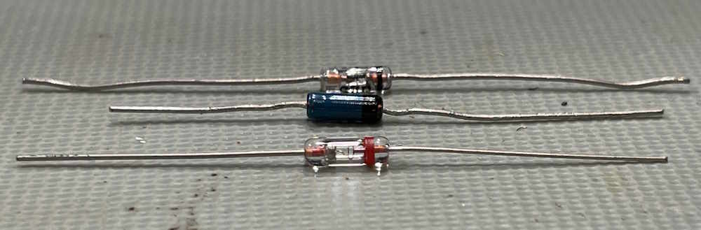
Here’s a bunch of diodes.
I’m going to test these parts. We have, from top to bottom:
A traditional 1N34A glass diode.
An unknown germanium - this may be a 1N60.
A Soviet type D9A.
All of them have well denoted bands. I’m going to toss in a 1N4007 Si rectifier diode (not shown) as well, just for comparison.
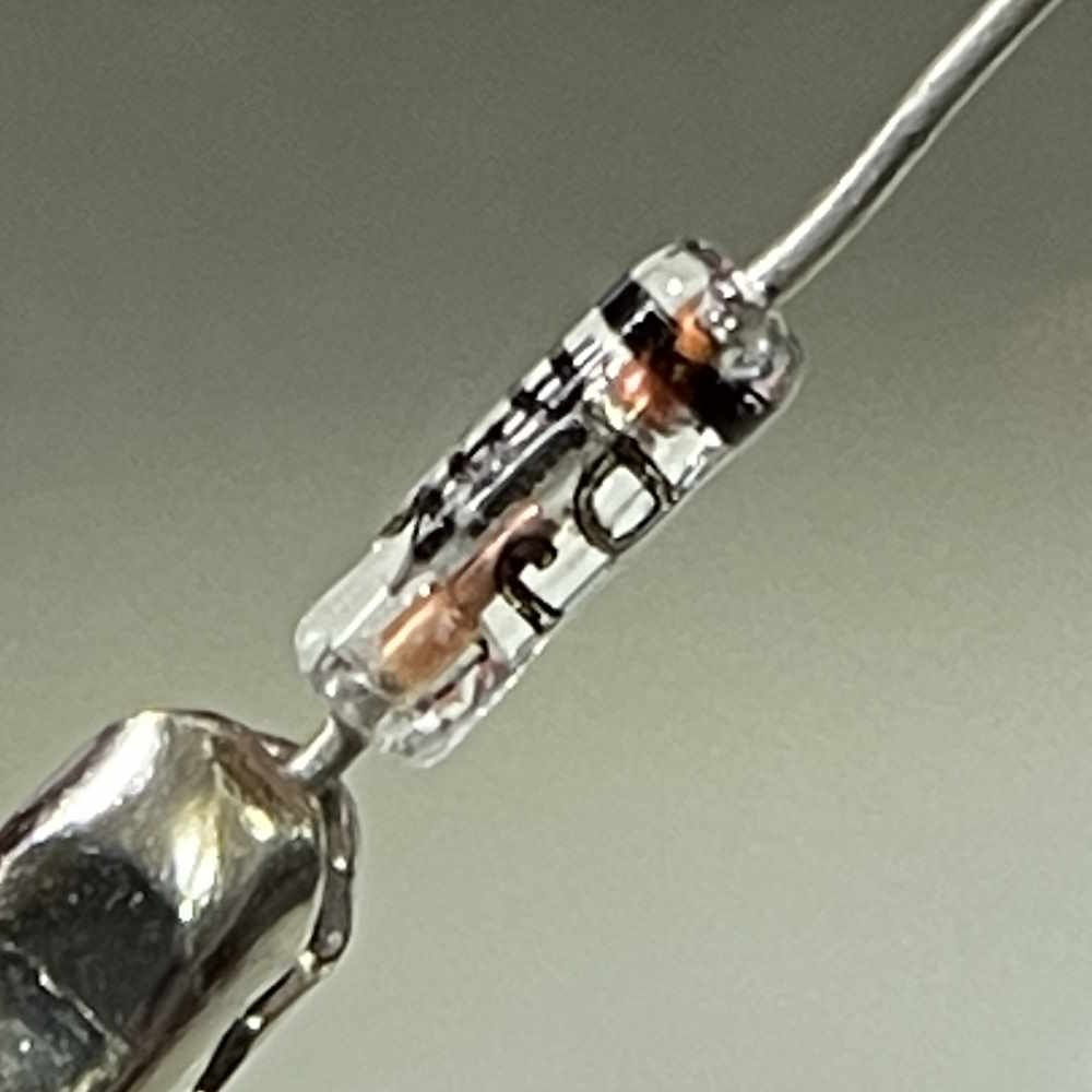
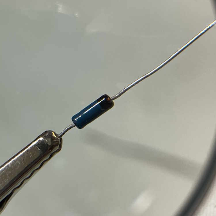
Here’s the parts as viewed through a magnifying glass. Of particular note is the Soviet part - you can clearly see the flying lead and the point of contact on the germanium crystal.
1N34A
Unknown germanium
Soviet D9A
Testing the diodes
What’s the purpose here? Well…the Soviet part has something interesting about it. If you’re familiar with how the diode works, you’ve already noted the issue.
Let’s test the parts, I’m going to be using my old reliable, a meter I purchased many many years ago. It has a diode function that tells you the voltage drop across the diode’s junction.
For diodes, these are the “perfect” theoretical voltage drops across a junction:
Silicon: 0.7VDC
Germanium: 0.3VDC
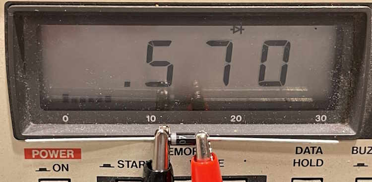
In reality, it’s closer to 0.5VDC and 0.23VDC, respectively. Let’s test the parts on the bench. First one is the silicon diode, for comparison.
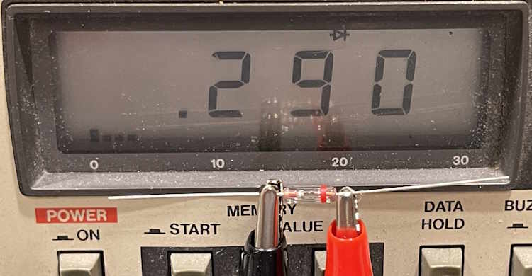
Note the negative lead of the meter is on the banded side of the diode, so we know that’s the cathode. We see the expected 0.5xxVDC drop of the junction.
Here’s the 1N34A:
That’s in line with the expected drop.
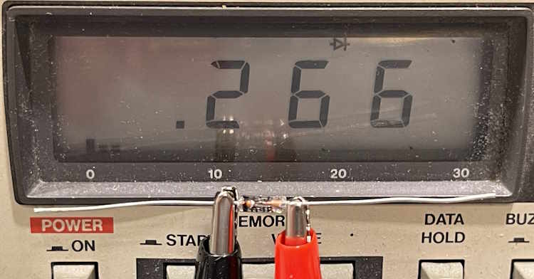
Here’s the unknown germanium:
Again, the expected drop.
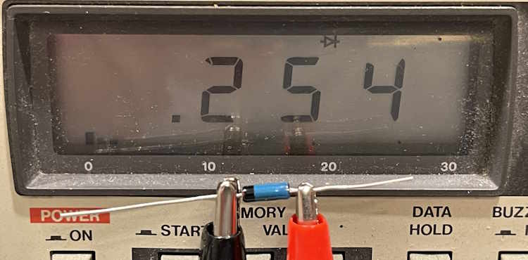
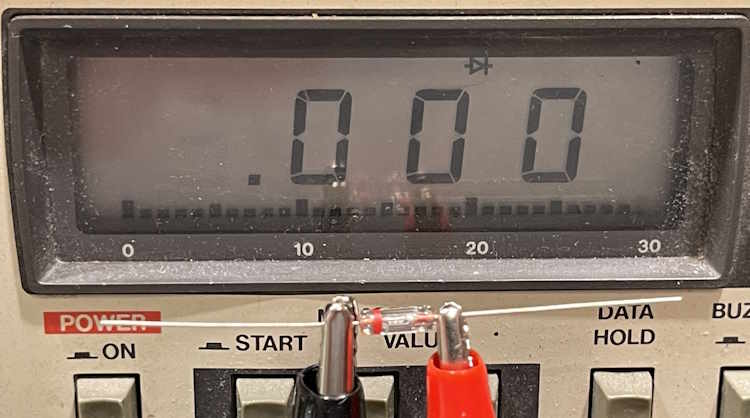
Here’s the Soviet D9A:
It’s correct, that’s zero. There’s no drop across this device, indicating the unit isn’t conducting. It’s connected correctly, isn’t it?
No - Soviet diodes put their bands on the anode. That is, they are marked completely backwards from what we accept as diode marking. Here’s the device properly biased:
There’s the expected drop. Completely backwards from what we expected.
Why is this important?
Soviet germanium diodes are the most common Ge diode available at this time, so they show up in a lot of places. Radio kits, fuzz boxes for guitars, small signal rectification circuits - anywhere a diode with it’s properties are needed. For a radio kit, it’s not really terribly important which side of the information you recover from the carrier, but if you’re trying to rectify a signal it’s very important. You need to make sure you install them correctly, and if you follow “accepted” conventions you’re not going to accomplish that goal.
Measure your part - that’s the best way to verify what you have.
The first ‘fest of the season has come and gone. Notably, the dearth of CB radios from the past few years has started to fade. Unfortunately, all of the older stuff has started to fade away. There was still some interesting things to be seen, and I picked up a few interesting things for later projects and checkouts.
A Commodore 64, now 40+ years old.
These machines were not cheap, that's ~800$ today.
A unique clock kit. I took it home.
I don't know, some…thing with cool meteres.
cf2026-diskettes-wereboar.jpg
cf2026-equipment-wereboar.jpg
Another table of random things. These are getting rare.
OSHA? No sah!
A homemade flight sim rig.
Nothing much to hear these days.
Just junk on the floor for your parts needs.
People love those deaf-as-a-post Knight radios.
Some old meters. I took the Keithly and Heathkit.
A Hong Kong special. Probably deaf when new.
I never understood those weird Mac packages.
There's the orange “T” from Coshocton.
A lamp for your porch. Welding goggles not included.
A box of probes. I took the “EICO” style for my tracer.
Rat Shack Radios for days.
These used to be $10 all day. Not no mo!
A nice RCA radio.
A 27MHz RF curing machine. Could be someone's new linear.
Look at the size of that tube.
The business end of the cure. Cures…life, probably.
Almost got this and the next one as a real challenge project.
In bad shape…
Gimme one of those S-Pecans.
These are always a lovely piece of history.
We topped the day off with a stop at Arthur Treachers’ Fish and Chips, and then headed home.
Next up is Dayton, I’m planning on going all three days this year. As a reminder, you can still mail order a ticket - internationally until Wednesday, and domestically until May 1st. See you there!
The cutoff date to purchase tickets and have them mailed to you is rapidly approaching. For international orders, you have until Wednesday, April 15th to get your order in. For domestic orders, you have until May 1st. After that - tickets are held will-call at the door. If you’re going, the time to order is now!
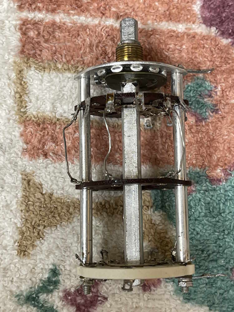
As the carbon film resistors on the range switch decided to go way out of tolerance as they were being worked with, I removed them all and decided to dump the switch assembly in the ultrasonic bath.
Watching the dirt lift off was quite fascinating…it just drifted away.
It’s not the easiest to see because the dark wafers don’t show much difference, but they feel different now. The ceramic wafer at the bottom is also much whiter, and some of the green growing on a previous owner’s mod is gone.
Once the new resistors are installed, I’ll give the rings a shot of cleaner-lube, and put some dielectric grease on the detents.
As the King of Hearts said: “Begin at the beginning, and go on till you come to the end: then stop.”
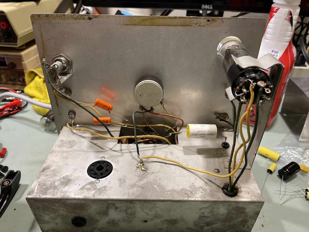
We’ve seen this thing is an absolute mess inside. It was built…ok, but then someone came along later and j-hooked EVERYTHING. I cannot figure out why, even Mister Wizard would probably be at a loss to explain this one. So where to actually start?
First of all, I did some cleaning on the device. The front panel was wiped down with some gentle degreaser, and all of the knobs/terminals were cleaned.
The only problems I’ve run into with the ultrasonic bath and these parts is the white paint on the chickenheads tends to come out - but that will come out with just water and a cloth as it’s so old and brittle. I’ve thought about this, maybe some white ink in a syringe or on a toothpick would be a way to re-mark them. The other issue is the pointer tends to change shape a little when you wash it in warm water. This old clear plastic bent outward - I actually don’t have an issue with this because they like to bend inward and scrape the face up. It is what it is.
Moving forward:
The top of the chassis, of course is a good place to start. This is the easiest (and most open portion) place.
On this top part of the chassis, we have the following delights:
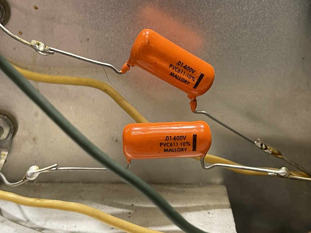
These are good quality parts, being orange drops…but the weird installation method. I assume that the person just hooked in when the old paper poppers were removed. I will remove these, and may use them in this device assuming I can figure out the date of manufacture. I’m guessing 70s, so…maybe not?
Sure would have been nice if I’d put that image here in the first place…
We also have this beauty. Again, a good quality part, put in with meh installation methods. I’ll remove it and put it in the “bench use bin.” Besides…the new part is of better tolerance than this one, which is essential for the circuit this one is in. Thankfully the hole that it runs into was insulated!
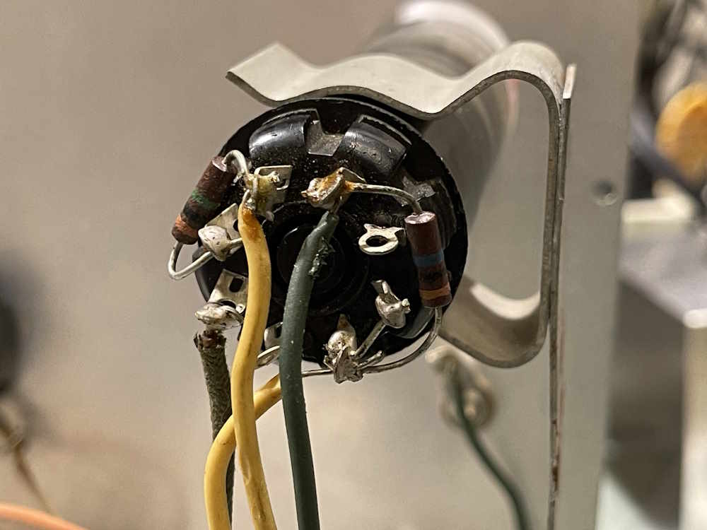
Last thing, other than wires, is the eye tube socket. This one, unlike the Olson TE-189 unit, at least has the wires soldered to the socket properly. I’ll clean those up and run new wires and resistors. Nothing critical here, but I’ll use 1% metal films just because they’re cheap.
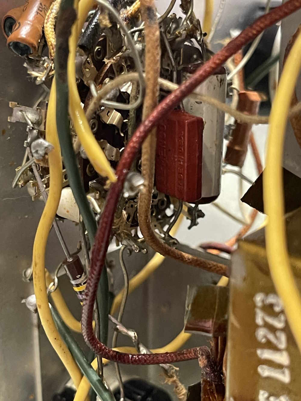
On mica capacitors
That red rectangle behind the chaos is a mica capacitor - or so we assume. (more on that later) It’s made by stacking layers of mica with metal foil - often with some silver in the mix due to silver’s better than copper and gold conductivity. Most will tell you these never go bad.
Yes and no. Silver can migrate in this type of device. You see this in radios where you get arcing in the IF cans on the little silver-mica capacitors - the silver oxidizes and creeps out, changing the value or even shorting. It’s a problem and will only get worse as time progresses.
So these can go bad. They can get silver migration, called Silver Mica Disease. They can get cracked cases and allow moisture ingress. The coatings can be suspect, collecting water or dirt that allows leakage. Just because you haven’t run across a bad one yet, it doesn’t mean you won’t have a bad one later. There are plenty of reports of people seeing these start to go funny in the 90s, and we’re now 30 years past that point. These devices are now 80 years old.
Why does this happen? It’s a combination of many things. The resin gets cracks in it you can’t see. These cracks, or the resin itself, allows and traps moisture. When you apply a high potential across the part, the moisture allows silver ions to start dissolving and moving towards the opposite potential. This creates dendritic growth that both changes the capacitance of the part, and eventually (and that’s a long eventually) it will short and die. If the case was improperly sealed, then the danger is double because then you have a known ingress point for water.
There’s another issue. Is this really a mica? Some manufacturers packaged paper parts like this too, thinking the same thing that later manufacturers did - that the coating will protect the paper, already known to be a problem item. It did, but you still get water ingress over time, and that’s all she wrote on that piece of soggy paper.
How about the part in this one?
It reads, value-wise, ok. Does it leak? I won’t know until I get it out, and it may not after I hit it with heat. Who knows?
The kit I bought for this device doesn’t have this part in it for the above mentioned reason of “these don’t go bad.” However, as I was told not that long ago: “You found this car in a barn, all hoses and belts are original. Do you want to drive it, or look at it?”
I want to drive it. Therefore…I’m getting an order of resistors and some other parts together for the unit, and will put a capacitor in the cart as well. I’m removing pretty much every other passive in this unit because it’s out of tolerance, is of poor installation quality, or is just bad. I’m not going to skimp on a single $4 part.
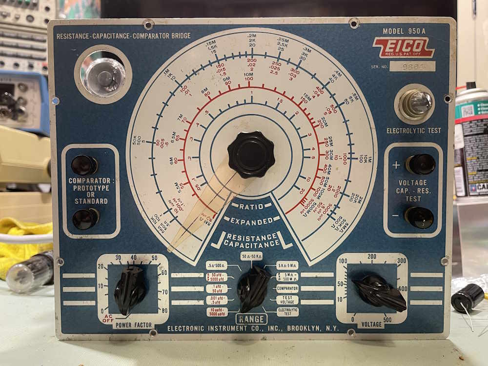
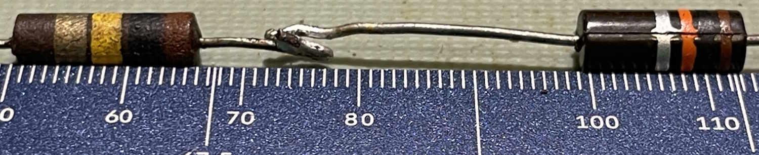
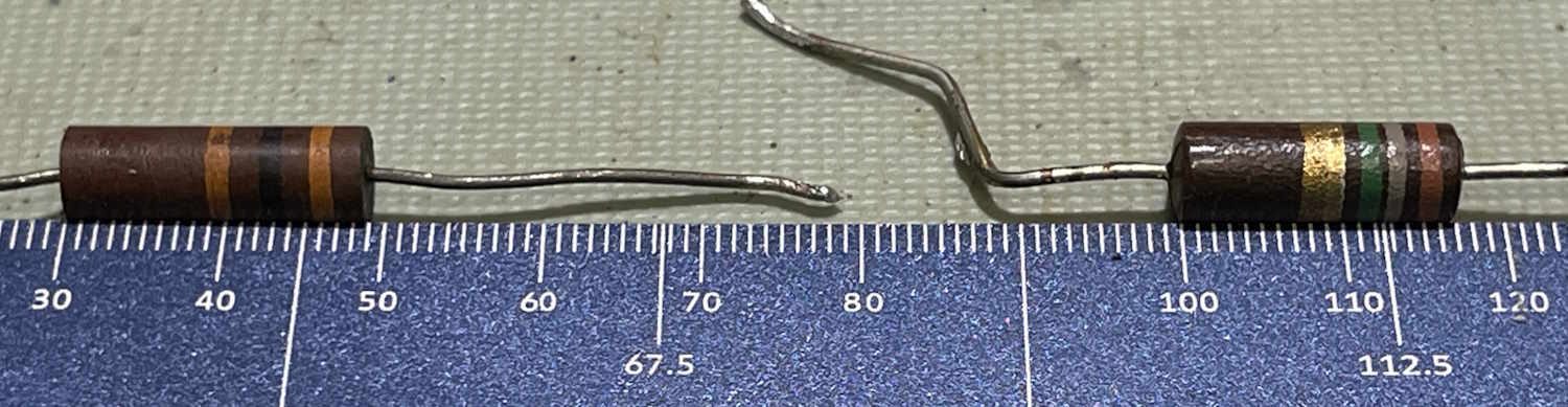
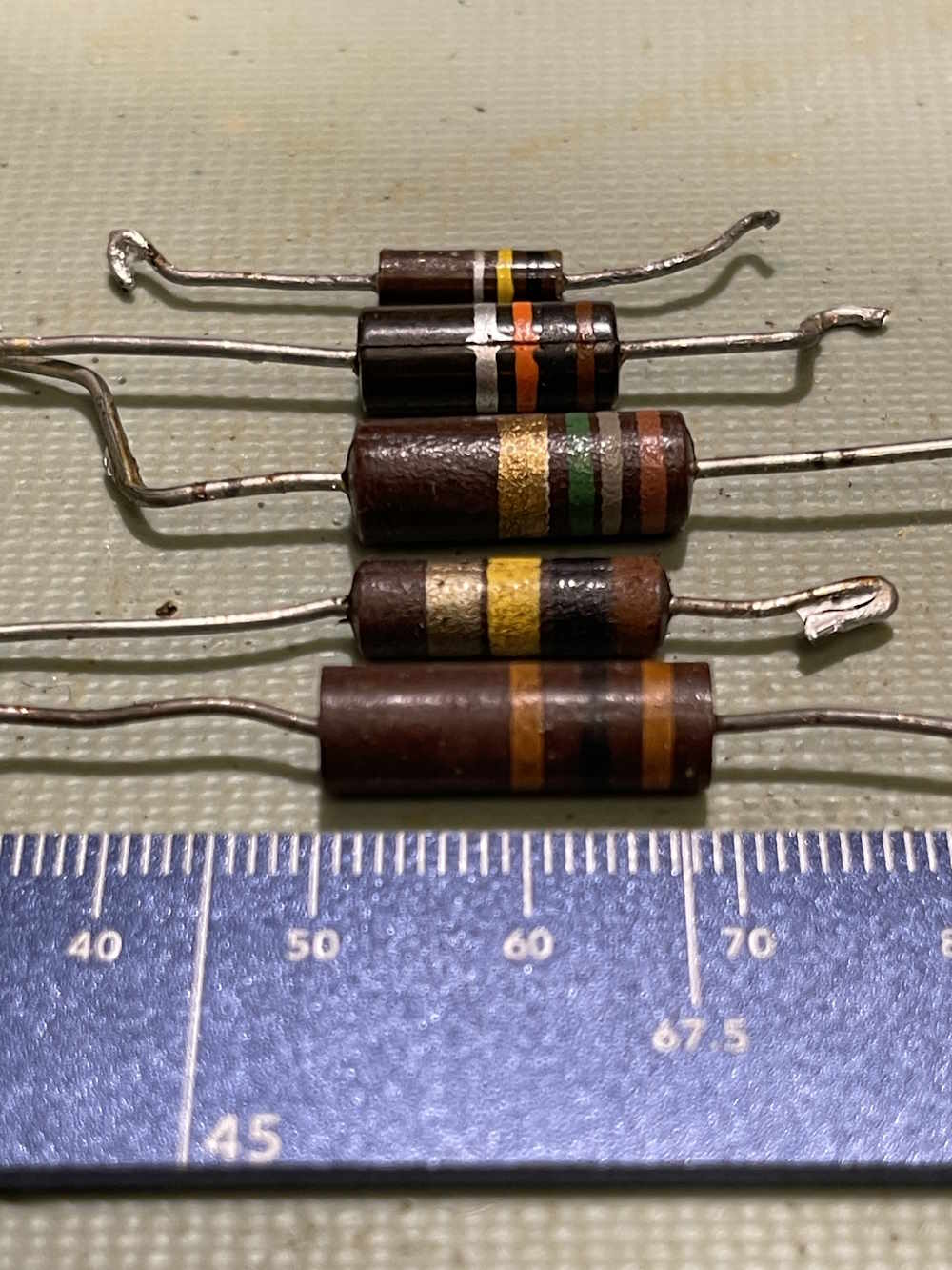
If you’ve worked on tube devices, you may have seen a resistor that looked like a higher wattage part, but was strangely long. For example, this 30kΩ 20% part in this EICO 950A RC bridge. It’s somewhat longer than other carbon parts:
Why is that?
Simply put, it’s for voltage ratings. This particular circuit has that 30kΩ part bearing the brunt of B+, and the entirety of 500VDC can be across that resistor A smaller carbon resistor would arc across and flame out.
Here’s a couple of examples. The first is a comparison with a 1W resistor.
And a comparison with a 2W reisistor.
For the 1W comparison, the higher voltage part is 16mm long, whereas the 1w part is 13mm. The 2W comparison offers a 19mm higher voltage part, and a 17mm 2W device.
This is purely to provide physical spacing between the two leads. More space, less chance to arc. If you see one of these unusually long parts, there’s something special about that circuit, and it demands your attention.
This is something that I just learned not that long ago, so…now you know!
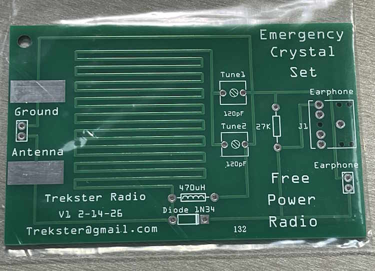
A “crystal” radio, or an AM radio that works without any kind of power other than that generated by the radio signal itself, is one of the staples of basic electronics. It’s something that’s always fascinated me, and while I’ve never wound one by hand I’ve built a few kits over the years and generally enjoyed them. It’s so named because originally, these would have used a chunk of some natural semiconductor like galena to make the detector - but in a modern sense we use a small crystal of germanium in a 1N34/1N60 type device.
This particular device is sold on a popular auction site, and is offered by the creator. What’s in the box?
Packing material! Just what I wanted. No, not really.
A couple of sheets of instructions, a couple bags of parts, and a PCB.
We have:
Two variable capacitors
A germanium diode of type D9K
An earphone jack
Two screw terminals
An inductor
and, a Resistor.
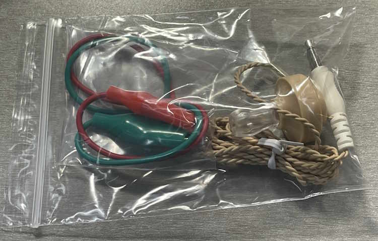
In the other bag, we have:
Two cut clipleads
A Piezoelectric earpice
Those of you who have been around for a while will recognize that earpiece as the same one included in every Radio Shack kit ever made. There are lost tribes using these as jewelry somewhere.
Also included is this PCB.
The board itself looks nicely made, and uses the copper as part of the inductance for the circuit. The only thing I see right off is the diode is going to be a tight fit with the leads bent down right at the body of the part. That’s not really good for a glass part, and hitting that with heat can cause damage - especially if you’re not careful to get in and out asap.
I spoke with the creator about the diode, he indicated that the lead spacing was widened in the latest batch.
But, I think it should be ok. We’ll see, I’m going to build this kit within the next few weeks. There will be one more post about the building and testing, stay tuned!