Saturday was a good day at the Hamvention. It was warm, things were drying out, and everything was open. A few vendors appeared to have left, but there’s always some that only attend Friday, expecting it to be the big day.
The mix of products has changed over the years. Gone are the big stacks of old test equipment, piles of old radios and televisions, and the endless sea of Watkins-Johnson equipment. CBs have faded as well from their peak a few years ago, and computer equipment is all but gone save for a few “classic” machines and newer hard drives that got replaced in the never-ending “moar stoarage!” quest. Hobby gear from the 60s seems to be common right now, with big radio gear still being common but lessening.
I picked up a few things Saturday:
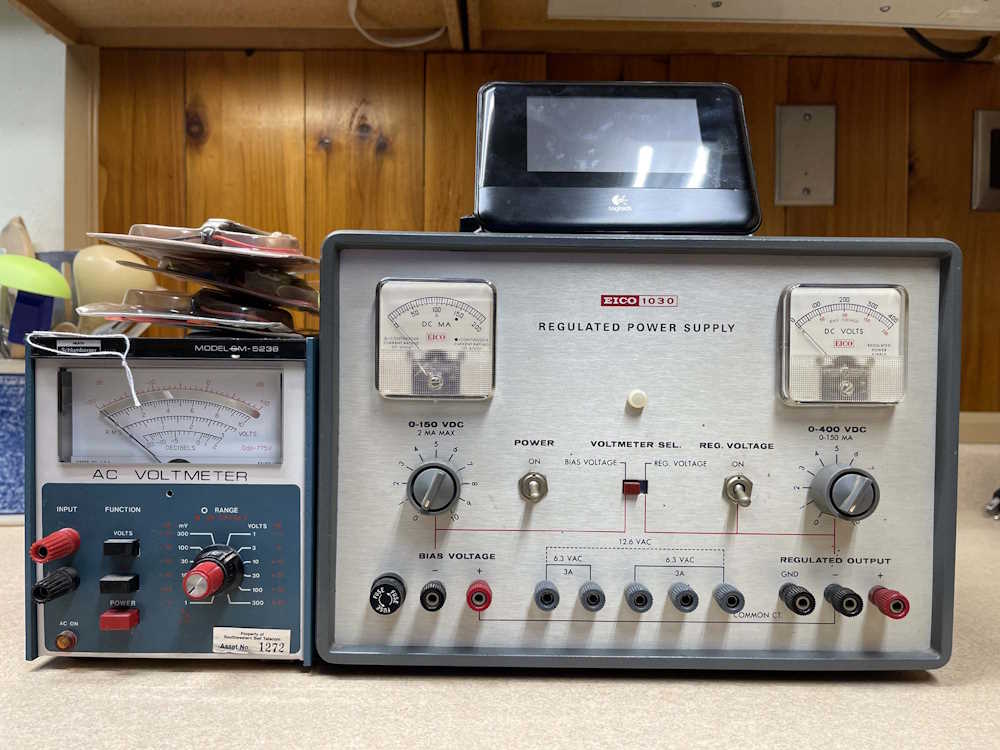
I picked up this Eico power supply. It’s designed for tube work, providing 400VDC and 150VDC for plate and biasing. There was a second one, not working, and I was going to offer on both but the dead one sold first. Probably for the same thing I was going to use it for - parts.
The little Heathkit meter is AC only, but the meter goes to the middle when it’s turned on. Something leaky or shot, most likely. It was last calibrated in 1995, was used by Southwestern Bell, and the cal house was in Dayton. Kind of a cool thing.
A manual for both items is in order before use.
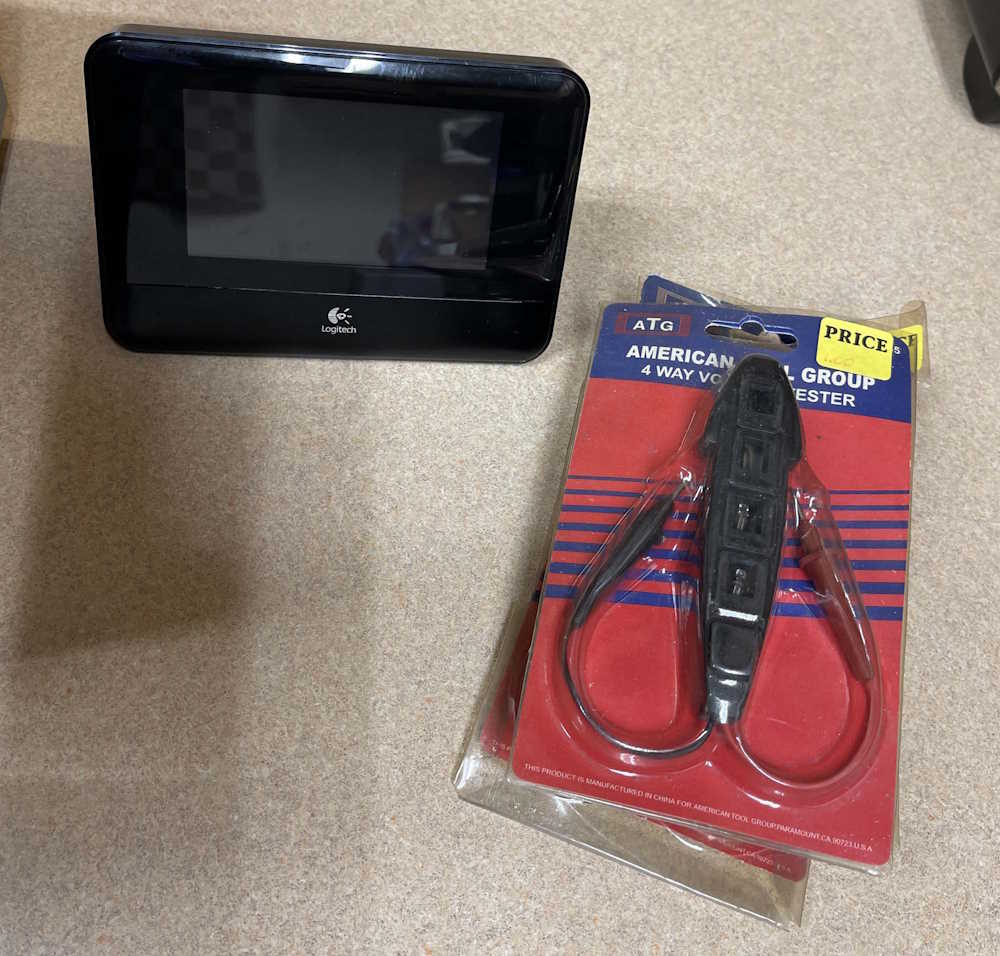
This Squeezebox Touch was in a box of random devices. Logitech used to have this awesome music player system that you ran on a server at your house, and you could connect multiple music players to it that played streams or your local library. They discontinued it because I guess you can’t sell ads in a service you run yourself. Regardless, the players still work fine and this clean example of one of the touchscreen models was cheap. I need to try it out, if it’s dead then oh well.
The other items are AC line testers. Unlike most, these have 120, 220, 380, and 440 lamps. At a buck each, I bought 3 and will toss them in the toolbag.
That’s all for Saturday, I was planning to (and did) go back on Sunday. I picked up a few more items to take home because vendors were willing to deal so they didn’t take it home. Stay tuned!
This year’s show started out rainy, and it rained until I was done browsing the flea market about 4 hours after open. Of course!
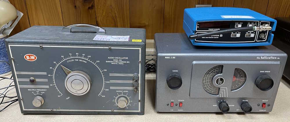
Really, the only thing I wanted out of the show this year was to find a Hallicrafters S38C. I had one of these years ago, and gave it to a family member. They swear they gave it back, but I don’t have it and I don’t remember giving it away. Not a big deal, it was a pretty poor example of the type but it did have a manual with it. I ended up coming home with a frequency counter - I need one to fix my other one that suddenly stopped counting, and got a good deal on a boat anchor of a signal generator. I also found what I came to the show for - an S38C.
The Frequency counter is nothing special, just a counter. It works. I saw it working at the show, so no problems.
The gods smiled on me because this S38C was sitting at a booth with a couple of other similar radios that an older gentleman was selling because he just didn’t have the time or interest anymore. It’s in great shape for the age. It’s missing the back, of course, and a knob was kind of busted. Not a big deal, the case and innards are in excellent condition.
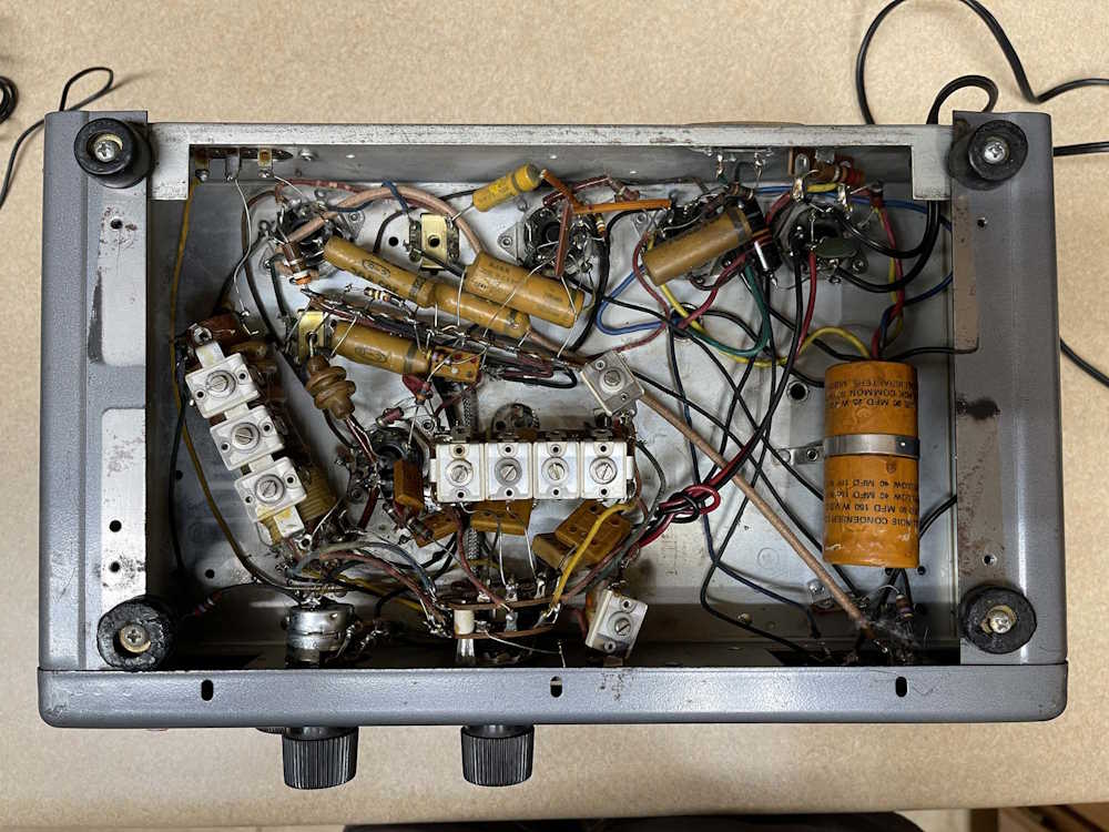
Everything inside is completely untouched. Bask in the glory of leaky wax paper capacitors and bumblebombs.
The filters are bad, of course. That’s expected, and the 150V capacitors won’t be too hard to acquire. If I can find some at the show tomorrow that aren’t super goodly chinesium, I’ll get them - otherwise, a Mouser order is in my future.
future me note: it has bad IF transformers.
The last item is the signal generator. It’s in ok shape for the age. What caught my eye is the beautiful flywheel tuning dial. Just a pleasure to spin and turn. It works, but has some issues - the signal kind of fades in and out. No tsure what’s going on here, I’ll open it later and take a look. However, when it does work the signal is quite nice.
future me note: it wasn’t worth repairing.
That’s it. There’s one piece I told myself if it’s there I’ll get it tomorrow, so we’ll see.
Not much this time, just some prep work for the big stuff.
First was to unsolder and remove the RF jack on the front and find something to put in the hole. This piece of plastic from…who knows…almost fit and will be secured with some RTV later in the project.
You’d never know, but the case was washed.
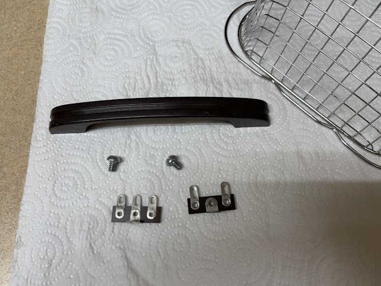
The handle and some hardware was given an ultrasonic bath to clean it.
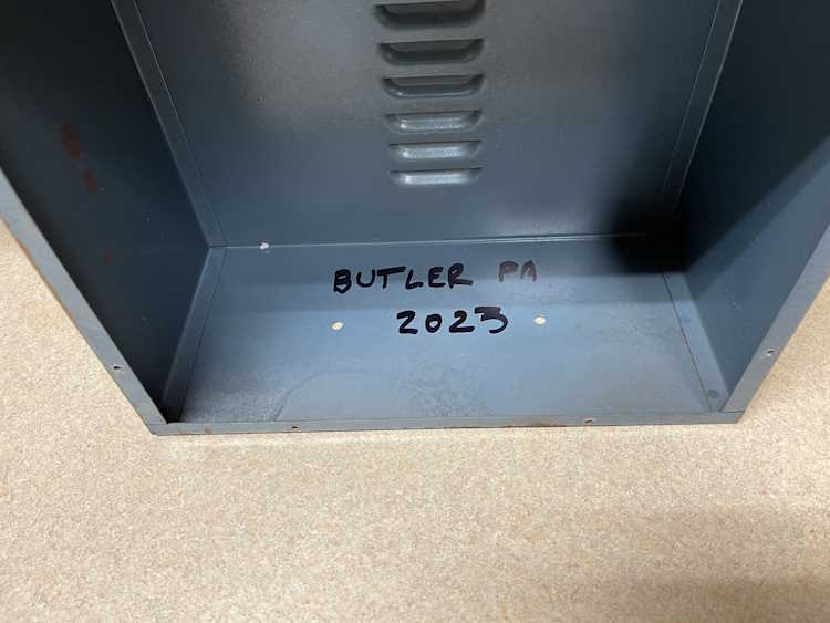
The location and year of purchase was noted inside.
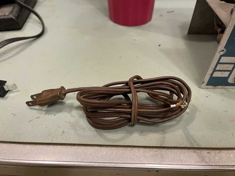
And the old, almost hard as a rock cord was removed.
Next is to start removing components. I haven’t decided if I want to do it all at once, or try to do it a part at a time. I can certainly get cleaner results removing everything and doing it all at once. I have the assembly manual, so - probably all at once. Stay tuned!
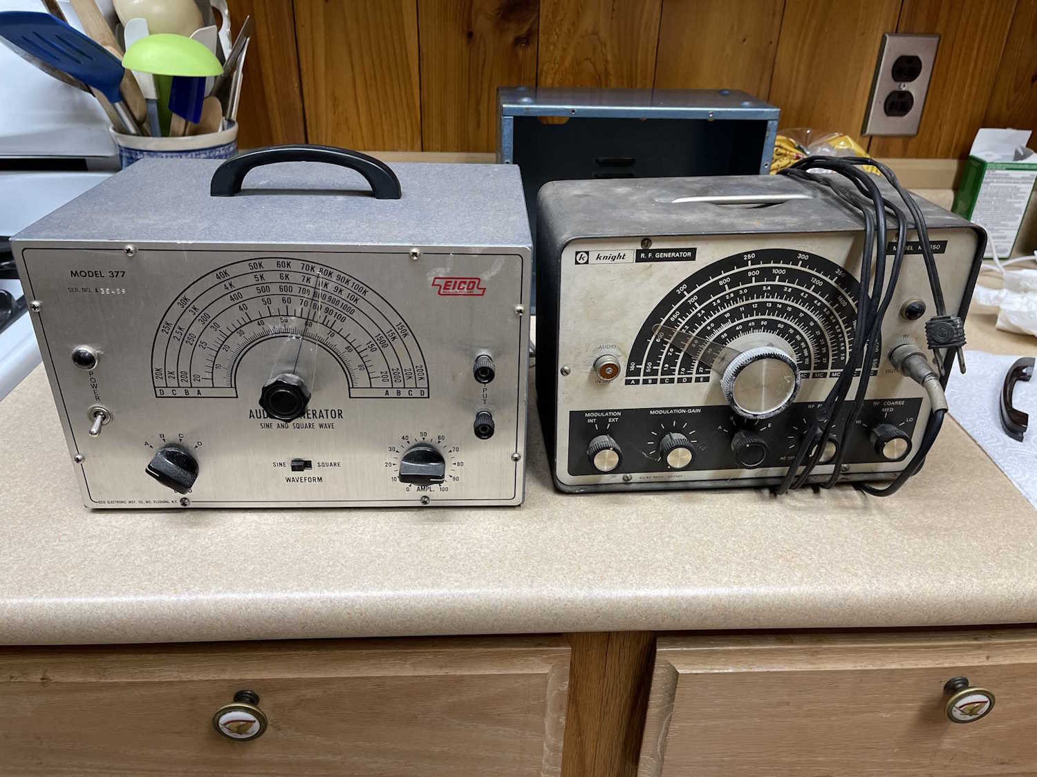
I really didn’t go to this show expecting to buy much, and I didn’t - I spent $30 and brought home these two items:
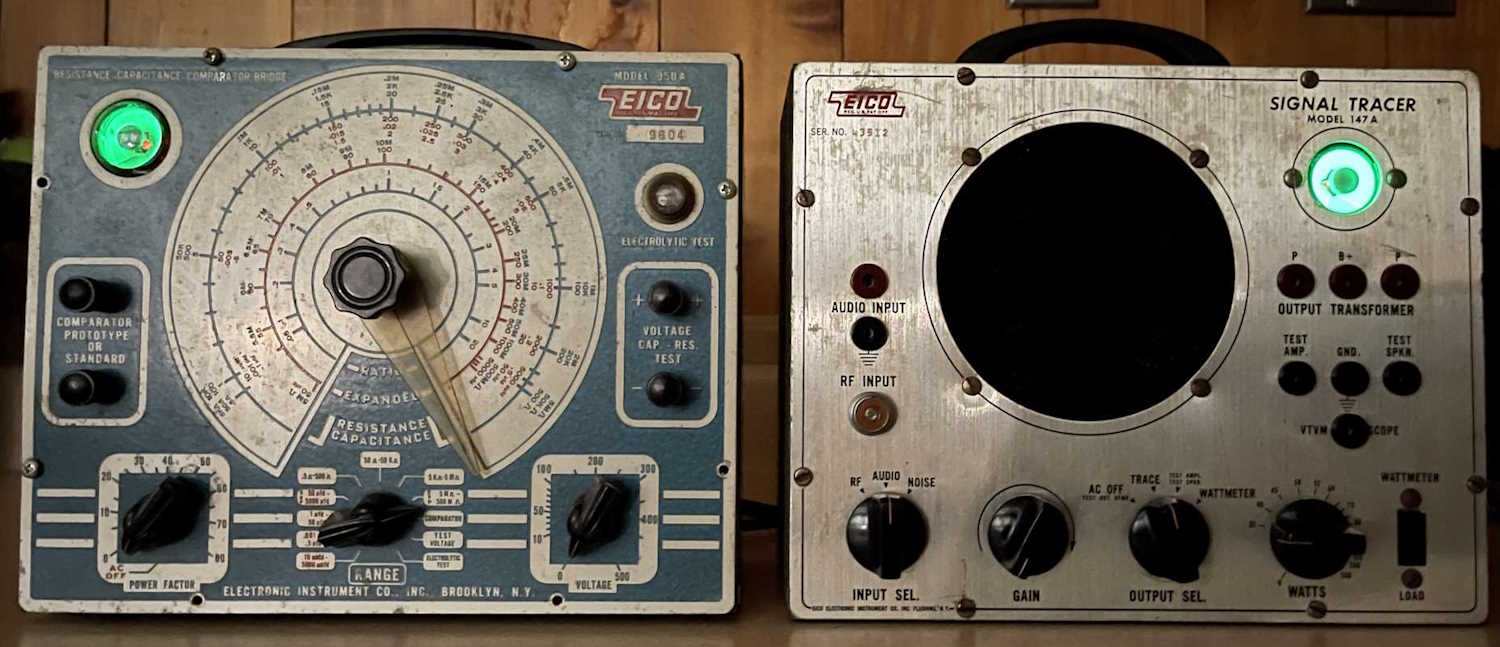
The audio generator on the left works, but has a messy sinewave output. I’m not sure if this is normal, but knowing some of the other equipment I’ve had from this era - it may be. There are some capacitors in the unit with high ESR, so I may play with it a bit before making further judgement.
The RF generator on the right has an absolutely miserable output, the entire bottom half of the output waveform is clipped off - which I thought was bad. Nope, they apparently overdrove the final amp to the point where that’s the way it worked. It also is overmodulated with internal audio, so this thing was a turd when it was new. I found some suggested fixes, so I may play with it a bit when time allows.
The RF generator was a “Offer I can’t refuse” thing - the guy said take it for $5? Ok, sure!
That’s all - I did want the capacitor checker in my show post, but I restrained myself and someone else picked it up for the low price of $40. Thank you rando for saving me!
I did it again. Too much stuff, but I’m going to blame some of the sellers for being so congenial about negotiating on prices! (Yah right!)
So, what did I bring home this year?
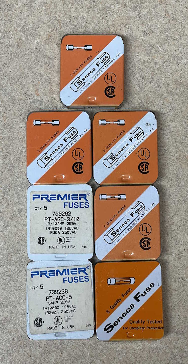
Fuses.
This vendor had a lot of different values, including a lot of fractionals that will cost you a small fortune if you buy them new, so I picked up some 1/3, 1/4, 15mA, and 1A varieties. What’s kind of cool about these things is Seneca Fuse used to be a Columbus, OH corporation, and one of the boxes is marked as such. The company was purchased by an entity called Russell Enterprises, which appears to have long since gone out of business.
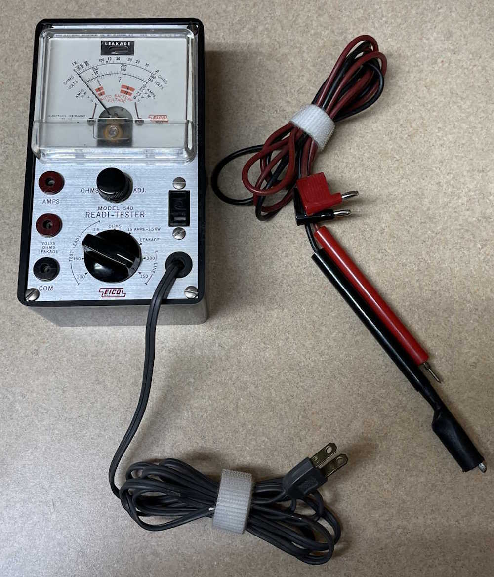
This is a cool little device that didn’t cost much. It’s a primitive hypot-type device that can test for leakage in a circuit. While primarily designed for appliances and other large current consuming things of yesterday, it still works great as a bench voltage monitor. It also performs it’s other functions without issue, so it was a good find - and it had the manual with it. I’m not sure what the leads were for, this device used EICO’s pin plugs. No worries, another set of leads on the bench is always a good thing!
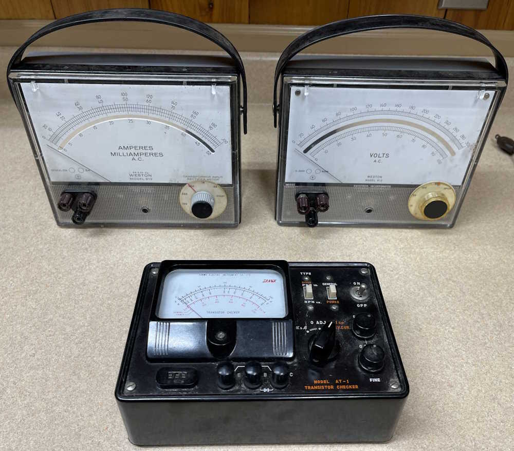
I actually only wanted the AC Voltmeter in this lot, but the seller was really good on the price for all three, so I came home with the AC Voltmeter, a current meter, and the oddball Sanwa transistor checker. The meters are nice dampened movements and work well, but I haven’t installed batteries in the tester to see if it works. Not sure I will, those little handheld device checkers do an excellent job of sorting parts and identifying things for you.
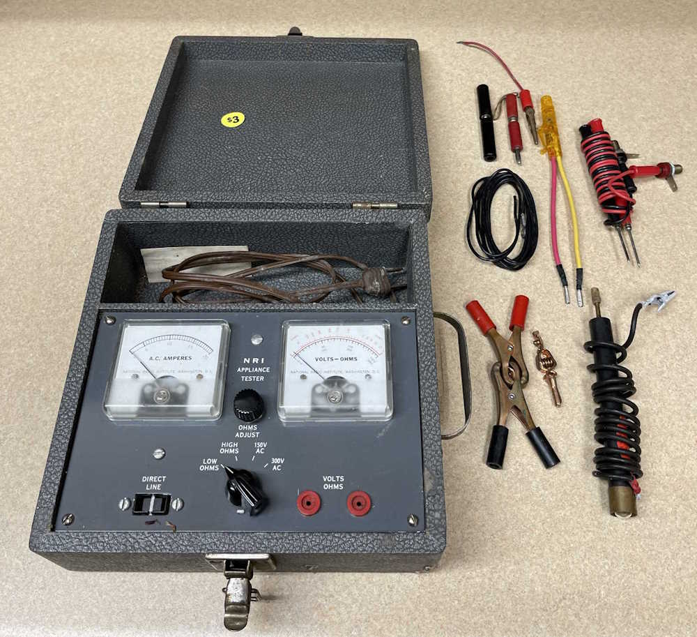
This little meter in a case was probably part of some course offered by NRI Schools, an early “distance learning” company. (Started in 1914 as National Radio Schools, ended in 1999 as NRI - changing tides on the electronics landscape did them in.) While it’s not really of much use, the real Mueller copper clips and other test leads were well worth the price of $3. The device itself sat in a basement for some time, and it smells like it - if I can get the smell to fade, perhaps I’ll find a use for it.
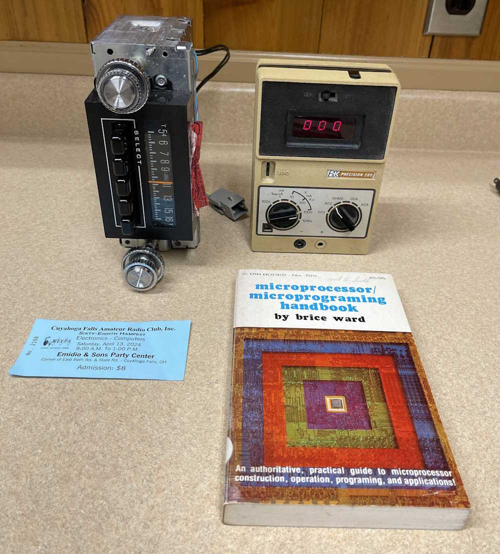
Here’s the odds ‘n ends portion of the program. An apparently new Ford AM radio that I got for a put-in-the-rack project, a B&K Precision LED voltmeter that matches my capacitor checker, and a surprisingly well written TAB book about early microprocessors. I say “well written” because TAB would publish almost anything. Some books were pretty good, but some were literally nothing more than a guy who wrote a book about taping LEDs to various things and called it “101 electronics projects.”
I don’t need more of these, but they were a good price for functional units, and they’re starting to get outrageously priced. These were checked for operation, and will go into storage as parts donors - or perhaps as resale units once cleaned up and re-capped. Who knows?
In all, it was a good show. I didn’t need to drag home some of that stuff, but I did. I’ll see you at the next show this weekend!
It’s not really important to operation, but having clean knobs and lenses on indicators is always nice. Since I have an ultrasonic bath, I’m going to use it.
The knobs on this guy are pretty cruddy, and the power indicator has a spritz of bronze paint across it.
While I’m removing the knobs from the volume and function selector, they get a shot of deoxit to clean and lube them.
Everything goes in the bath for 20 minutes.
In the end, they all come out nice and clean and ready to re-install!
Parts have been ordered, we’ll go through those next.
The Scott Antique Market has closed for the season in Columbus, with the next show happening in November. There weren’t enough things to make a post for each of the past few months, so I’ve consolidated everything from this year into this one post.
The normal assortment of radios, televisions, and other electrical oddities showed up, with a number of just interesting or other neat things.
I did pick up one item that will be the subject of it’s own post, but until then - here are all of the things I found interesting from the last three shows.
An unusal Ideal toy from the 1970s?
A “Bandmaster Senior” radio. This image ended up on radiomuseum.
The Bandmaster's back.
A closeup of the VFO on the Bandmaster.
The bike everyone wanted in the 1970s.
An optician's cabinet full of test lenses.
8 tracks cartridges and Pink Panther valentines cards.
This Humble Oil tiger really doesn't care about your problems.
No longer a blue light special.
When a snake dragon T-Rex stands on your rocket, it's time to stop drinking.
A couple of radios and “I believe in believe.” Sure thing?
Some nice radios and a Sears clone pong game.
A rather worn radio.
Right off the boat from Hong Kong and deaf as a post.
A couple of table radios from the late 60s.
Your new Sega System awaits.
A small Sony television.
A small battery power early Sony B&W set with frog that's so high he sees the faces.
A small Aiwa reel to reel pocket tape player with mic.
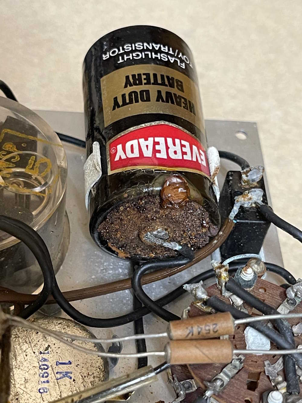
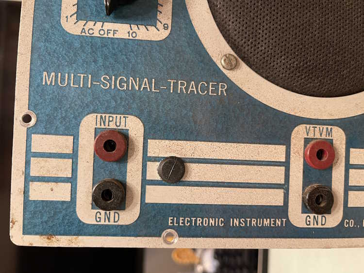
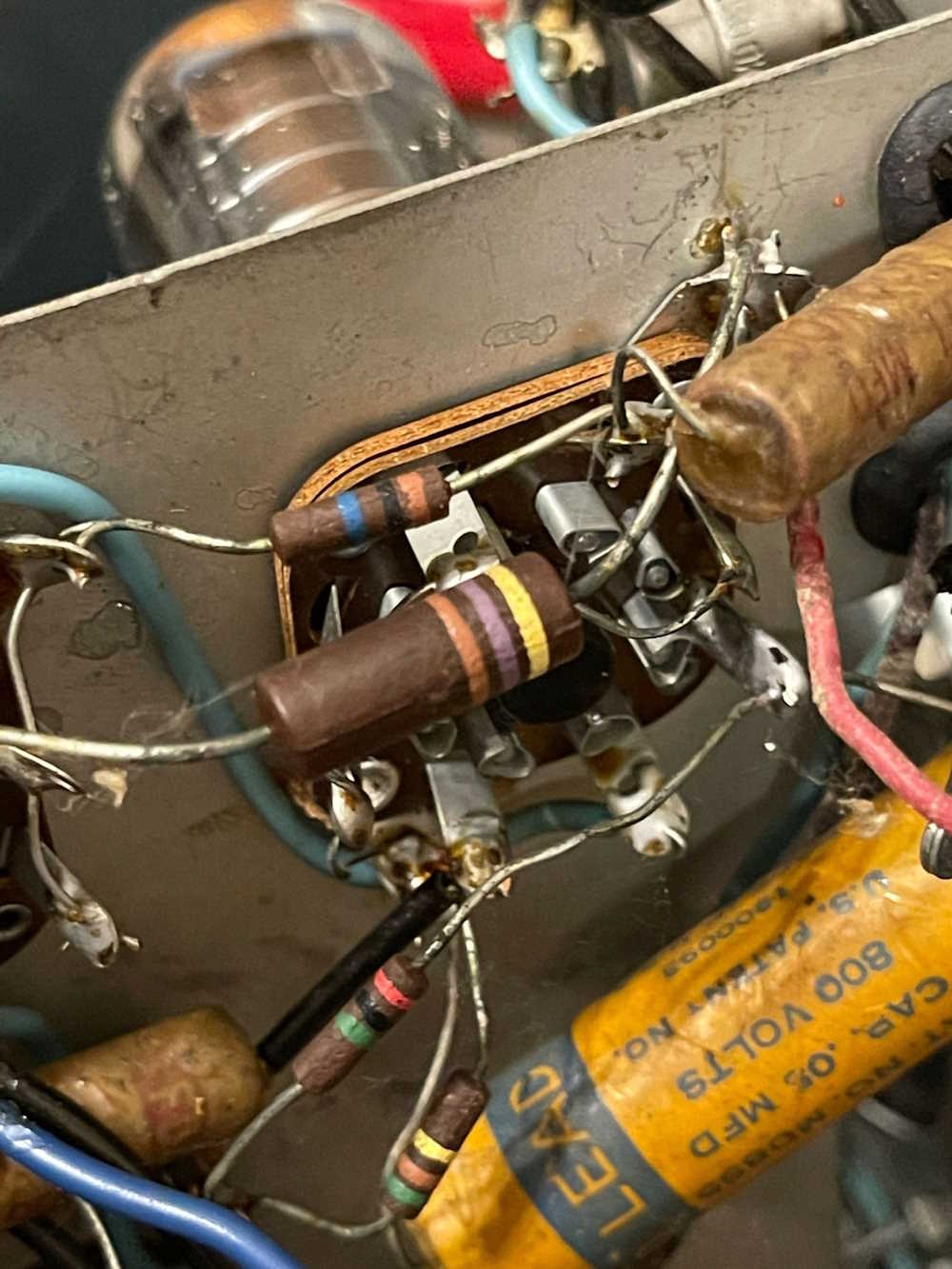
I sat down with an Eico 145 Signal tracer this weekend, evaluating what it would need to put it back into daily service. The answer? Pretty much everything. Leaky wax capacitors, carbon comp resistors that are 50% off of their marked value, and a few “doesn’t appear to ever have been installed” parts complete the list of this thing’s issues. It’s amazing that it’s still working, but I would bet that continued operation would destroy the tubes in short order.
The large 470Ω resistor in the foreground was of interest. A quick shout out to a friend confirmed that this was a 2W part, not a high-voltage device. This makes sense, as the resistor could potentially dissipate 600mW at maximum plate current. It’s also interesting because there’s supposed to be a 10uF bypass capacitor across that part, but it looks like it was never installed!
Right under that, of course, is the across the line capacitor. That ’splodey boi gets replaced first.
A quick trip to mouser for components is in my future.
I picked this unusual device up from an antique store in rural Pennsylvania, near where the groundhog works one day a year. It’s a fairly large place and prices vary, but it’s worth a couple hours of your time if you’re into that sort of thing, see the link below.
(The place seems to only have a facebook presence, and I’m not going to post one of those dirty links here - but here is the local chamber’s page for Yoder’s Antique Mall in Punxsutawney: https://punxsutawney … 73c05f142052452104c6.)
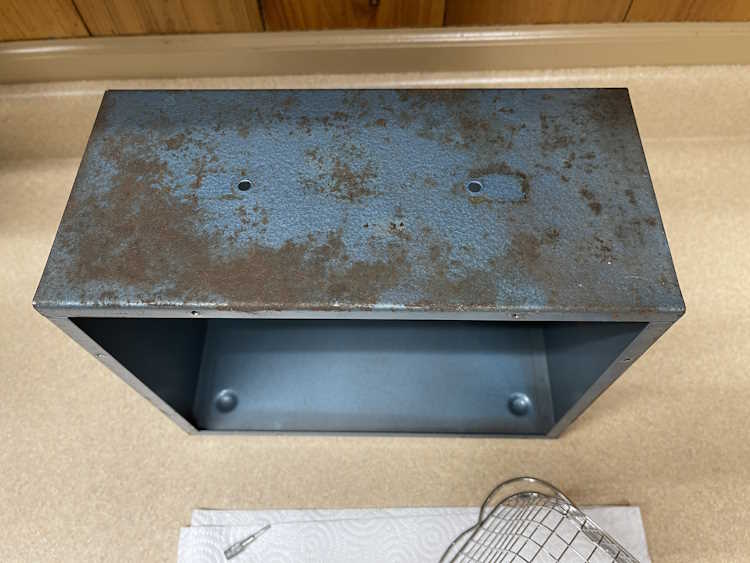
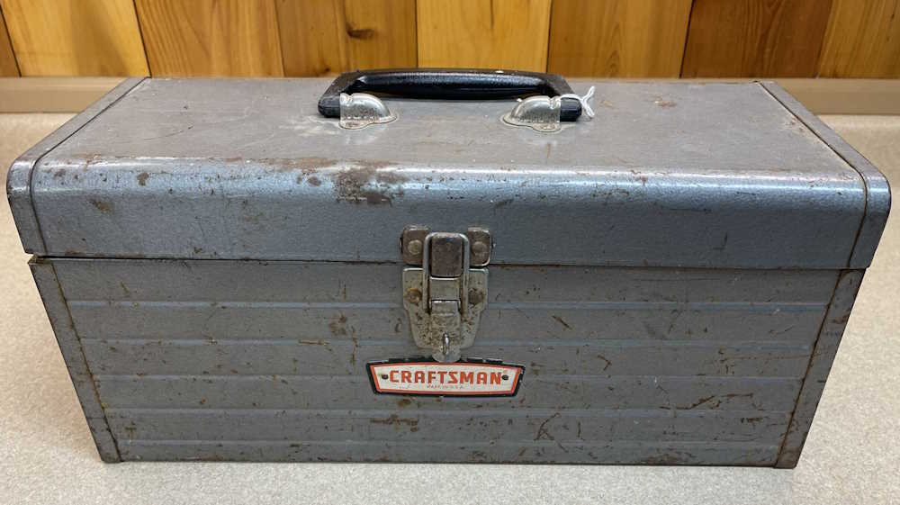
It’s a toolbox! Yeah, right on! Well…no, unless you’re interested in old toolboxes. It’s a fairly nice example of something from when Sears used to make things worth more than the metal it was stamped from. It’s what’s inside that I was interested in.
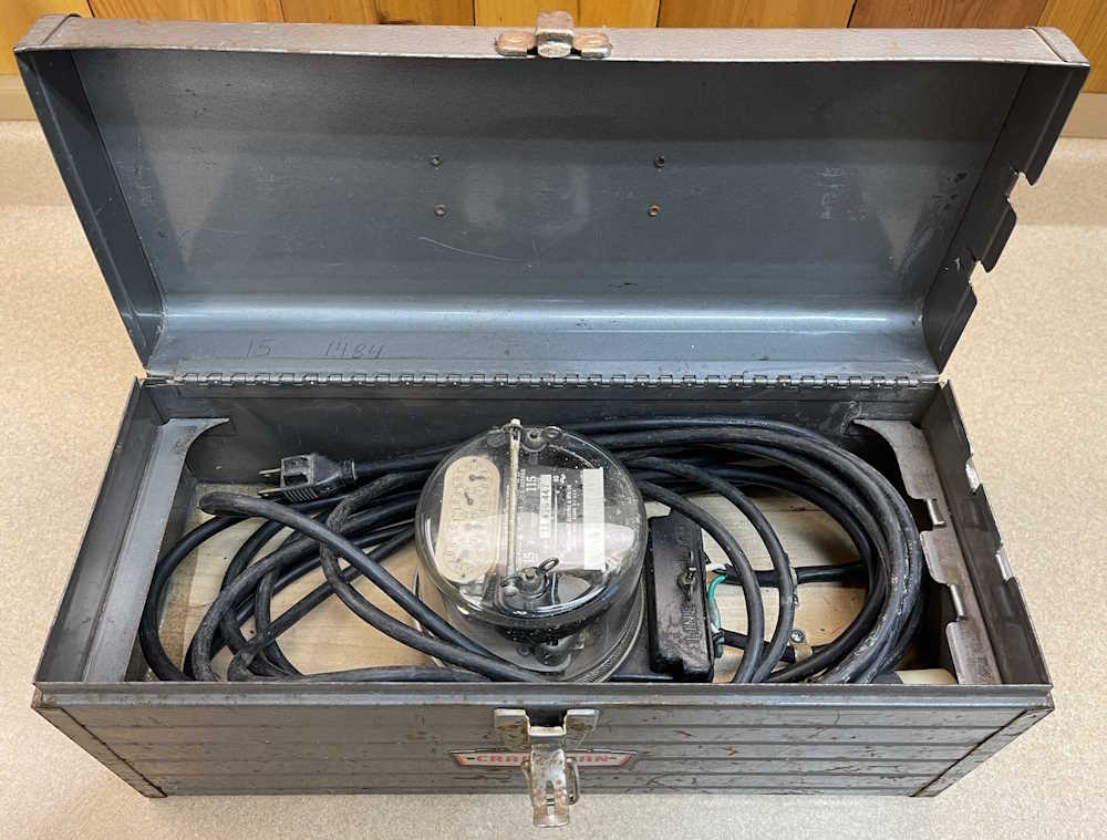
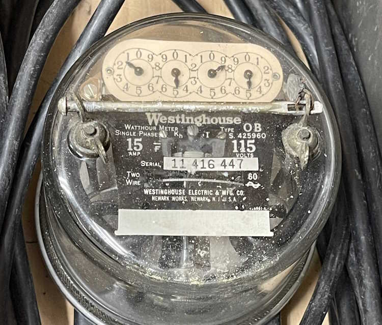
It’s a demand meter! Yeah, right on! Well…yes, but there’s something unusual about this one. It’s a 2-wire, 115VAC unit. While this is similar to what you would have on your house (or would have had before the electronic switchover,) those are usually wired for 230VAC instead.
This one appears to have been meant for sub-branch metering at some point, as evidenced by the easy-to-remove wiring compartment at the bottom of the meter’s housing. Whomever had this before me took advantage of that in that they wired a plug and outlet in line with the device - perhaps as a jobsite meter to pay the site owner for power consumed? Not really sure here save that all of the cable is pretty stiff and in need of replacement if it was going to be used.
Overall age of the device is in question as well - it looks to be 1930s, but Westinghouse probably made these things for decades. I suppose I could try and track it down by serial number, but who knows if those records still exist?
I tried it out by hooking it to a kitchen appliance with a heating element. It works as expected.
I’d like to get it out of it’s silicone covered metal box for a good cleaning, but that’s a project for another day.