The EICO 150 Solid State Signal Tracer redux, part 4: Yeah, that doesn’t work.
Thursday, May 28, 2026 at 11:48:22
Last night, I sat down with the EICO 150 and started to do the final wrapups on the unit.
Apply a signal.
Nothing.
Excuse me, what?
I focused on the function switch, but it seemed to be working properly after some study. I was able to put a signal in after Q1, and have it work, so that really threw me. I was able to bypass the input blocking cap on Q1 and get more signal, but highly distorted. So what’s going on here?
I decided to try the transistor(s) I pulled out for Q1 and Q2, starting with Q1. Removed the new Q1 and just tacked the old one back in. Immediate signal improvement. A check on the new Q1, and it’s just a diode now.
I get a new transistor for Q1 and check it. It’s good…and there it is.
Leads. The pinout on the transistor is different than the OEM unit.
I replace Q1 and Q2 (which is also a diode now) and I have output loud enough to make your ears bleed.
Rookie mistake. That’s on me. Always check your parts, and pay attention to what your tester is telling you.
Next post is actually doing the final tests I wanted to do, and to try and change the sensitivity of the output meter a little. Stay tuned!
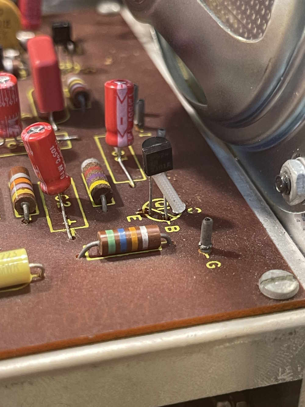
I’m not sure why I didn’t run that lead behind the other one, instead of in front. Who knows.
References
Youtube playlist: https://www.youtube. … yAcib71v-995pS_-4jDr
Manual: https://wereboar.com … 0and%20Parts.pdf.zip
Fixing the speaker: https://wereboar.com … -and-final-thoughts/
Next part of this series: https://wereboar.com … mistakes-were-fixed/
Previous part of this series: https://wereboar.com … part-3-replacements/
Wrapup and final thoughts: https://wereboar.com … -and-final-thoughts/