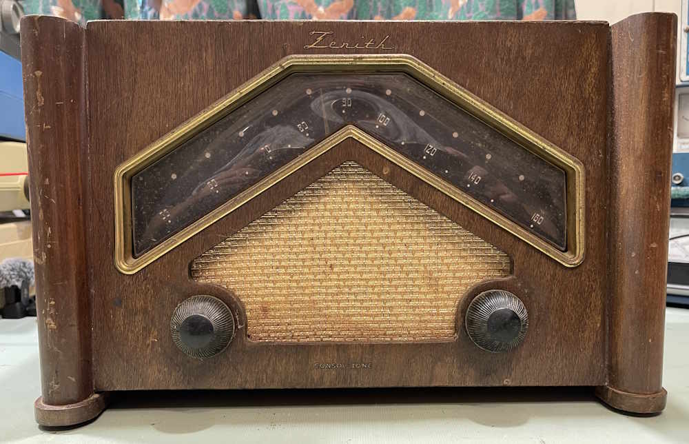
I picked this interesting example of a radio up at the Findlay Hamfest last year (2025.) It’s a Zenith 6D029, and was made around 1946 - so just after the war. It’s visually appealing:
It’s in decent enough shape for the age. The cabinet is all there, but the finish is eh. That’s about all I expected for the age.
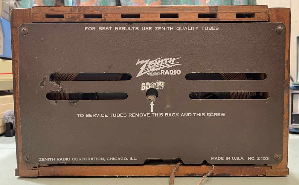
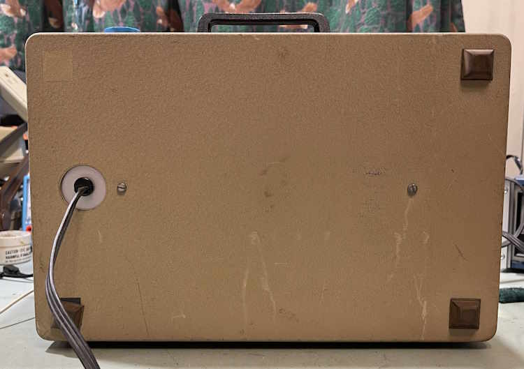
The back panel is all there, although just a little damaged. That’s really unusual for a radio of this age.
The cord, of course, is in mint condition. I could plug this thing in right away, I’m sure. (Or not. Probably not.)
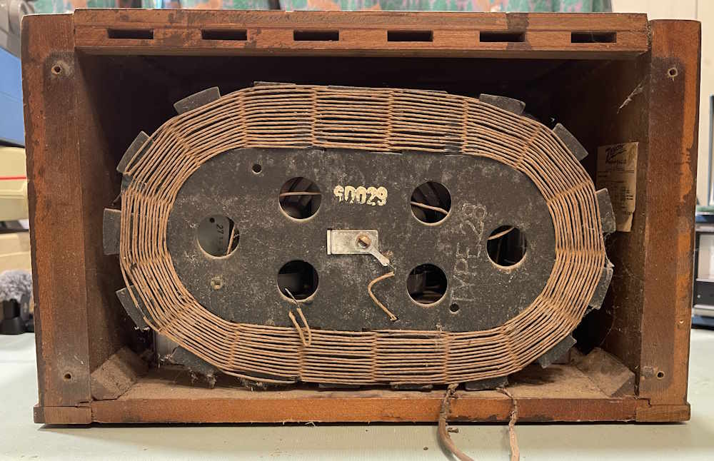
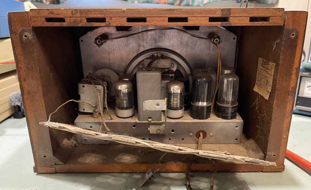
Removing the back panel reveals the antenna.
The OEM label is still inside.
Oh boy, loctals. Those are always fun.
The chassis is nothing unusual for a radio of this vintage. It’s a 6-tube unit, and has a tuned RF front end. It should be a solid performer when it’s peaked up. There’s only one OEM marked tube in this, so it’s seen a lot of use.
This is listed in Riders 15, Pages Zenith 26 and 27. I have that manual, and when I can get the book clasp to release, I’ll photocopy them and post them in the library.
Right now, one of the knobs is refusing to come off, so I’m deciding on ways to release that. When I’m able to get that off, I’ll pull the chassis and we can inspect the underside to see if anything has been done to this radio over the years.
Stay tuned, quite literally!
Next part of this series: Coming soon.
Wrapup and final thoughts: Coming soon.
While those of us here in the states celebrate our country’s 250th birthday, Projects from the Bottom Drawer celebrates a much more humble acheivment - that of it’s 5th birthday.
On July 4th, 2021, I set up pygg.xyz as a way to move my personal dealings off of a very breached gmail address. It had recently been in the 2021 LinkedIn breach, something I still get fallout from 5 years later as mailers insist that I’m actually a business and do I need help with employees/receivables/publishing/etc.
At the same time, I decided to re-open this blog - it had been hosted on blogger.com. I quicky found that .xyz domains had little trust in the internet world and set out on a search for another porcine-related site. Wereboar.com had recently been released by it’s owner, so I made the purchase and here we are.
Pull up a chair, have a slice of cake, and thank you for joining me these past 5 years. I hope to present strange junk and weird projects for many more.
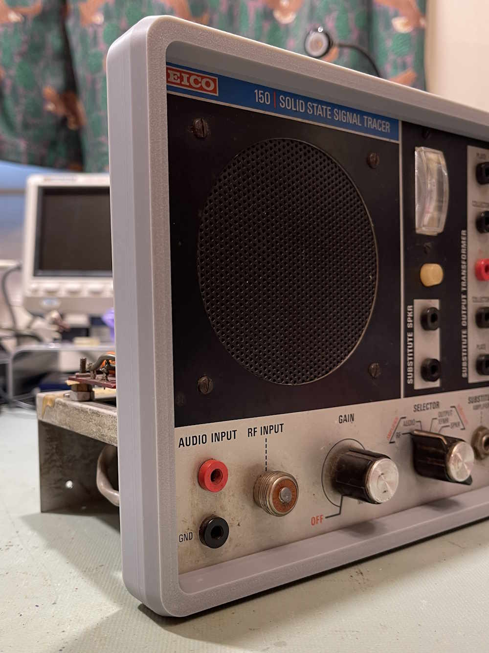
This is kind of an unusual device in the tube tester world - it’s the only “Lunchbox” style device that I’m aware of. Most devices of this nature are suitcase or other lay-flat devices.
I picked this guy up at Athens 2025, for a really cheap price. The reason for that price is someone accidentally splashed acetone on the front panel and destroyed some of the lettering. I don’t really care about that, you can still tell what it was.
The back is nothing special, and just has two screws to hold the chassis in.
Someone attached some mangled GC pin straighteners to the top of the unit. I’ll probably take these off.
Inside, it was obviously a factory build.
Almost everything in here is laced, save for a few things…
There’s a special place reserved for people who do this.
The only part of concern in this unit is a blocking capacitor of the Elmenco style. It’s dated 1974, which is surprisingly late for a tube tester. This can be easily changed but is it really worth it?
So let’s test something. I have a 6X5 laying around from the recent EICO 950A rebuild. It’s a NOS tube, let’s see how it works…
Yeah, that’s a good tube. But, remember - this is an emissions tester only. It’s a glorified go-no-go test, but it at least will tell you if the tube is working. Sort of.
This one isn’t going to need anything except maybe that capacitor. Probably not even that.
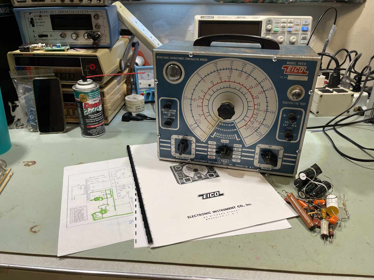
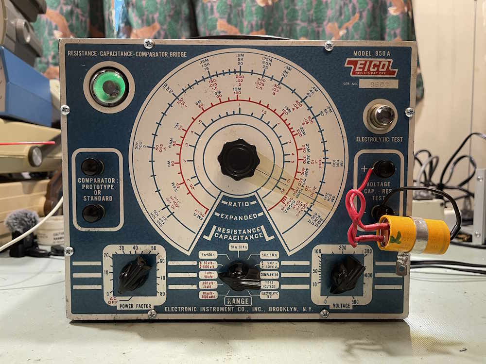
The EICO 950A has been completed. While this wasn’t really a complex build, it was challenging in that the previous owner made a mess of it before I got it.
This unit benefitted from remove the component/replace the component methodology that I used, where possible. It wasn’t possible in the power supply, which was a horror show, but everything else was easily replaced as it was taken out, as not to have too many components on the bench and too much “Where did this go again?”
The capacitor kit was purchased on eBay, and that’s what I’d like to talk about the most during wrapup.
Capacitors…too little, too late?
While the kit I purchased contained good quality parts, there were a few issues:
1: The mica capacitor in the measurement circuit.
Mica capacitors are generally thought to be bulletproof - but they are not. They are subject to the same issues as the Automatic Electric IF cans - that is, silver mica disease. You’ll be told this isn’t the case and that a mica is good forever, but searching online will reveal more than one person mentioning how they saw these starting to fail in the 90s, just 40 years after their common use.
We’re now 35 years past that, and these things are suspect. They haven’t failed - but they are suspect. First problem, is it mica? Paper parts were made on a similar body type. Second problem, these have miniscule surface cracks in the coating that have developed over the years. It’s not a matter if, it’s when they will fail. Will that be in my lifetime? I have no idea, but a new part is cheap, and there’s no excuse not to replace it.
In particular, I had a hard time getting a stable reading on the one in my unit - possibly because of moisture ingress over the years. The surface of the part didn’t look that great either, to be honest.
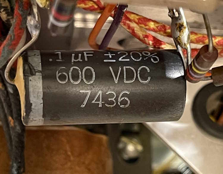
2: The main 8μF filter.
There’s nothing at all wrong with the part in the kit, but B+ in this unit is 600VDC - and that’s at a reduced line voltage. If your line is running 125 like most do today, your’re going to exceed the value of this capacitor by a wide range instead of the 7VDC I was exceeding it by. While the capacitor is probably going to hold up to this without too much issue, a weakened or older part could pop. As higher voltage parts aren’t really easily available these days, the best solution (even if it’s not a good one) is to take two 350VDC parts of roughly double the capacitance, put them in series, and use that. I’m planning on doing that at some point, but not right this minute - stay tuned for the addendum to this project.
While this 600VDC capacitor will probably handle 607VDC just fine, always use parts rated for what you’re doing. I like to derate by about 80%, meaning that for 600VDC I’d use 750-800VDC for this part.
Another thing of note was the 30kΩ resistor that feeds the main circuit. When I did the final parts placement, I joked about having to use two overly-exacting parts, i.e. two 15kΩ 0.1% 15ppm resistors to make up a 30kΩ because I didn’t seem to have any. Looking back at my notes - I probably decided to go this route originally because I couldn’t get a 30kΩ part, and decided to use those 15kΩ units for just that.
I didn’t replace the tubes like I had originally planned because the eye I purchased wasn’t a whole lot brighter, and the 6X5 tests similar to the new one. I’ll stick those aside for later use or other projects.
The challenge with this one was simply in the figuring out what the previous owner did, not in the doing. I now have a good working example of this device in my collection, even if the physical condition of the device isn’t the best.
Battle scars on test equipment are fine by me.
There’s another EICO 150, a Zenth Consoltone, and an EICO 249 waiting in the wings. Stay tuned!
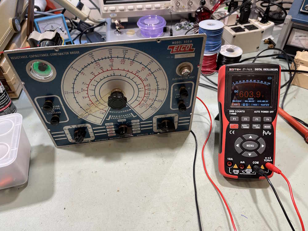
I did some basic power supply checks to see how things were performing:
That’s the voltage across a 600VDC capacitor. Line voltage here has been reduced to 115VAC to be more in line with what this thing was expecting when new. That’s not good, and this is even with a well-used tube. It rode as high as 607VDC, and if your line is 125, you’re going to see perhaps 612VDC or more.
There’s a chance that, if left on for a long period of time - especially with higher incoming line - that this capacitor could pop. I’m going to have to fix that. For reference, this is the main filter in the unit.
This is the other filter capacitor in the unit, and it’s a far more reasonable 145VDC. Well within the capacitor’s ratings.
Let’s see it work!
For a test, I took a 20+20μF part removed from another device. Checking with a modern meter reveals one section of this unit to be ~24.6μF. I hooked the part to the unit, and dialed in until I reached a good eye opening.
The eye opened wide, indicating that the part was useful and not leaking everywhere.
After a bit of finagling with the dial, I was able to set it to the proper place. This is about the only calibration you can do to one of these - take a known quality part, measure it, and adjust the dial until it reads what it should. Don’t have a capacitance meter? Use a high-quality film resistor instead.
The unit is functioning as expected, so beyond fixing the filter issue, we’re done! One more post, and then on to some new things.
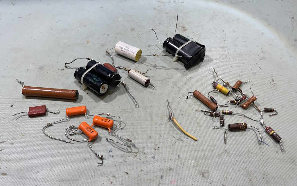
One of the things I like to do with units I rework is save all of the components and check them when work is finished. Since the EICO 950A has been completed, it’s time to check those parts.
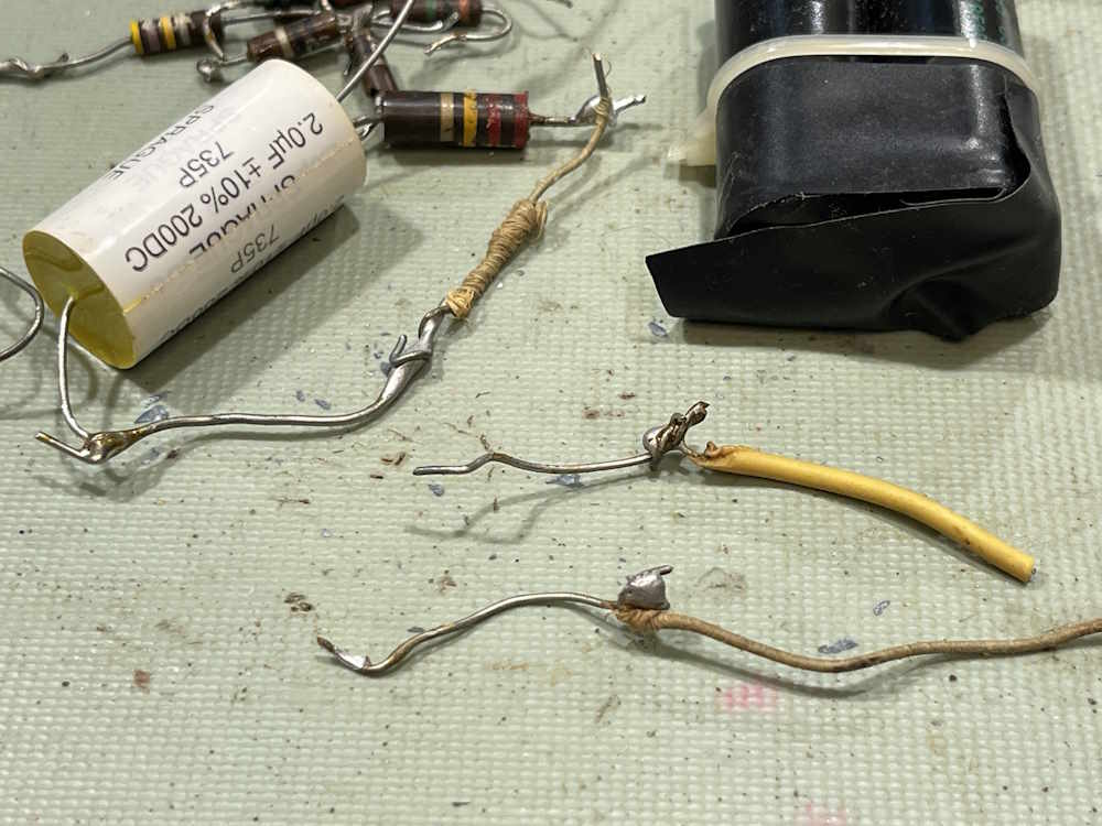
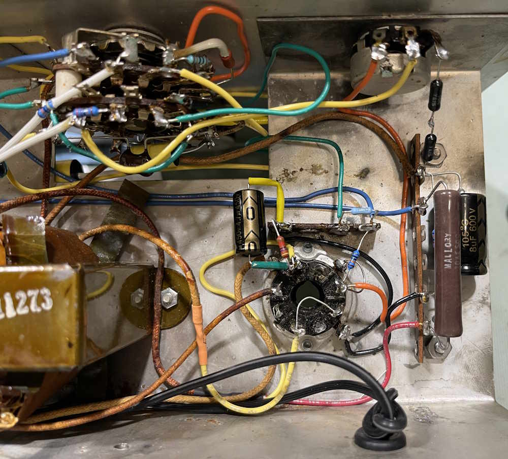
I know I’ve said this before, but I can’t say it enough: This thing was a mess. Someone cut every wire, every part, and J-hooked it back in. The wire…sure, that was some old thread-wrapped stuff and the few pieces left could have generously been said to have insulation. The parts, however? Wow.
Here’s everything that was removed from the unit. Most of what the previous owner put back in was of decent enough quality, even if they weren’t the proper tolerances.
Here’s some of the lovely connections made in this device:
That’s not even the worst of the lot. There were a couple of 4-splicers in there.
For the most part, the components that were newer are still in good condition, with only the resistors being problematic - as carbon comp resistors are. Surprisingly, most were reasonable for their age, so while this thing definitely shows signs of being stored damp, that didn’t seem to affect the components much. I didn’t do a “good/bad” on this one, as most of the parts weren’t original.
In all, this was more of a problem than it looked - slow and steady won here, and everything is back where it should be. Next up is the final check, and then the wrapup post with some thoughts on this unit if you have one of your own. Stay tuned:
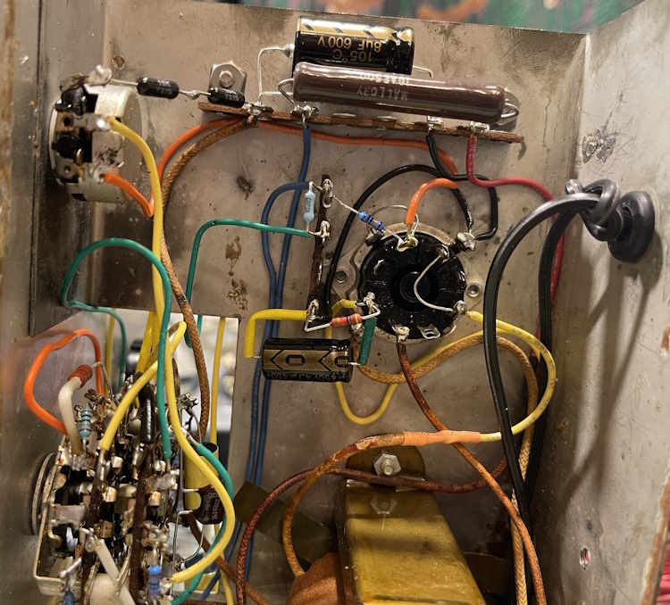
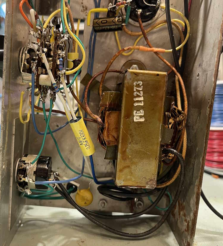
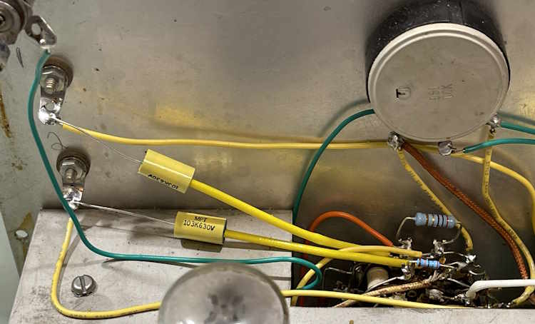
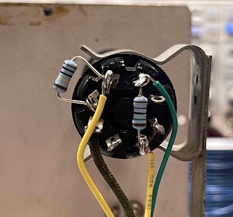
This has been a long journey of removing and replacing things in this unit. When I started, it was “can I actually do this?” But, it’s been done. All of the components, save the transformer and the pots, have been replaced with new. All resistors are now 1% film, all capacitors are now new electrolytics or modern film parts. I even have some new tubes for the unit.
This part was finishing up the power supply, and running lines and parts for the eye tube circuit, as well as adding a terminal strip for the line cord. I had planned on adding a terminal strip on the power supply side, mostly because the OEM build had everything jammed onto that one little strip and the tube socket, and I wanted to lay out the parts in an easier to see manner. I used a long strip, and it turned out decently.
I was going to put the AC line on this strip as well, but decided to move it nearer the switch, so there’s not AC running all over the place. I used a single position w/ground strip for that, and all of the incoming AC is now close to itself.
The only issue I ran into here was R7, which runs from a potentiometer on the face to the negative side of the power supply. I can swear up and down that I ordered the part - a 30k resistor - but these were not in my stock. I either ordered them and “put them away,” or I didn’t order them. No idea which. To fix that, I took some comically over-spec’d resistors and made a 30k unit. So…there’s two 15kΩ, 15ppm, 0.1% resistors making this part up. That outstrips pretty much anything I’ve worked on to date!
Here’s the photos:
The next step is to check the wiring, re-install the eye tube mount, and then turn it on! Stay tuned!
The trim ring on this EICO 150 was a complete mess. It started shattering in transit, and didn’t survive much longer on the bench. Here’s what it looked like:
A friend modeled a new ring for me, and we printed some examples. I chose a couple of material colors - gunmetal gray and silver. This unit is going to get the gray ring, and it looks pretty good.
The new ring is a solid piece. For screws, I discarded the original screws and went with a short, course-thread piercing screw. That seemed to work better, and the material definitely requires the course threads.
That’s one issue taken care of, next part will be jumping into the electronics themselves.
When I set the documents library up, I didn’t give enough thought to the naming conventions. Before I get deeper into things, it’s time to correct that. I’m making some small changes to where the docs library resides.
You’ll still be able to find the new docs library at https://wereboar.com/docs/ - the same as before, but there are now two folders: public and protected.
Public is just that. Documents I can share. Everything that used to be in wereboar-documents is now here, and you can simply edit your URL to go to the new link. Protected is documents of interest to what I’m working on, but can’t share for whatever reason - primarily copyright. These are password protected but will be moved into public if the situation allows.
If you happen to find anything broken, please let me know. I’m going to do a couple rounds of searching to make sure I have everything cleaned up, but this will take a few days.
Here’s a piece of relatively useless but interesting information - at the time I wrote this line, there has been 805,545 view on this blog. The most popular post is the 2025 Hamfest list: https://wereboar.com … mfest-and-show-list/.


