An EICO 249 VTVM: Wrapup and final thoughts.
Friday, August 14, 2026 at 13:30:18
The EICO 249 is complete.

This unit was purchased at the Cuyahoga Falls Hamfest in 2022, and has sat around for a while waiting it’s turn on the bench - primarily because I knew the entire thing, range switch and all, would need rebuilt. While that seemed formidable at the time, in reality it wasn’t that bad.
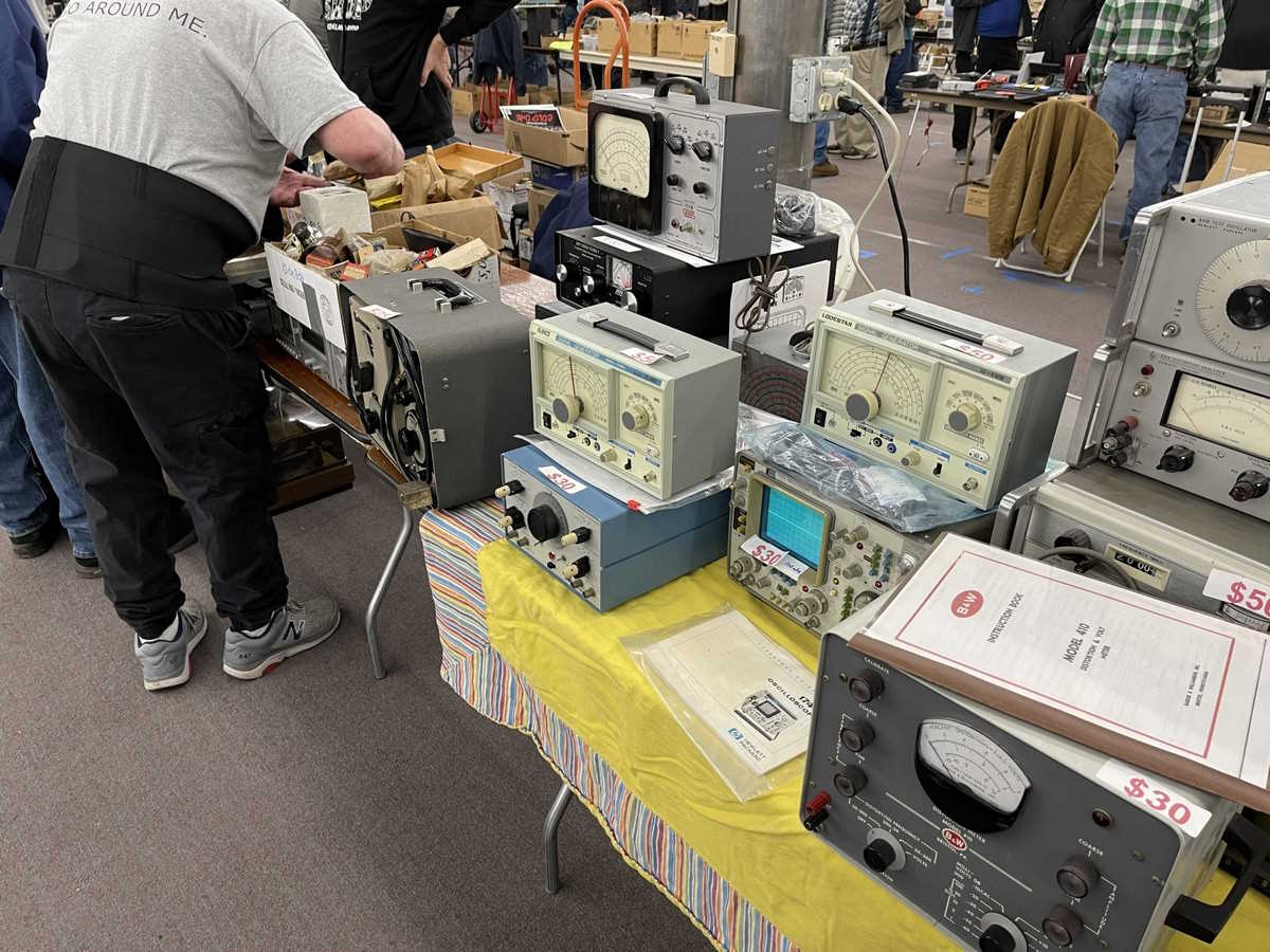
The device had been purchased “rebuilt,” and I knew it probably wasn’t. And…it wasn’t. The inside had new components, but they were wrong values, wrong voltages, or in some cases, just defective components. I’m not sure how the device worked, but I had only tested the DC section and found it to be operational. The defective components are in the AC side of the device, and that’s not as important to me as the DC side is. The ohms side isn’t important at all, so I didn’t even put a battery back in after completing the build.
I did get a donor unit, which was helpful - the range switch came from it, and allowed me to pull parts, drop it in the ultrasonic bath, and get a good clean part to start with. Resistors had to be made from standard values, as the oddball stuff that EICO used were not available from normal sources. That wasn’t any real issue, it just required using some calculations to arrive at the needed values. There are plenty of calcs out there that will allow you to generate unusual values from standard ones, if you need such a thing.
Past the range switch and it’s rebuild, the rest was a teardown and replace. A couple of resistors had to be made, including a really strange 82MΩ unit that ended up being created from 4 other values, and covered in shrink.
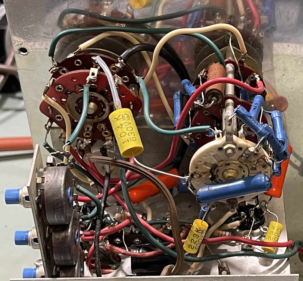
The before picture:
The after picture:
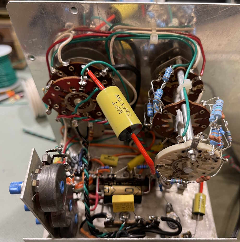
Almost all of the wire and cable were replaced save a few jumpers, and of course the transformer wire. The capacitors were purchased as a kit from an eBay vendor: https://www.ebay.com/itm/116116838477 named “Affinity For Artifacts,” and resistors were all made from standard values in series or in parallel using a calculator that I found online: https://mustcalculat … s/resistorfinder.php.
Problems during the rebuild
The first problem was that of the 12AU7 socket. Pins 4 and 5 of the tube are connected together, tying both ends of the heater together. This effectively gives you a 6.3VAC tube. When I purchased the unit, these two pins had a massive solder blob on them. It wasn’t just careless assembly, the socket pins were broken and the previous owner had coated everything with solder to keep the pins in place. That was a simple socket replacement. While it did require drilling out, it wasn’t a terrible job and didn’t take long to do.
The second issue was that of how the AC was run. Originally, it flew up to the switch and met the transformer lead, also on the switch. The other side was on a terminal strip that connected the 9.7Ω battery resistor, and then to the battery terminal. I didn’t like this, so a larger strip was installed. The AC comes in to a terminal. One side hits a safety capacitor and the transformer, the other side connects to a twisted cable that flies up to the switch and back to the safety capacitor, which is also the other side of the transformer. The hot side is switched to avoid having hot anywhere other than the one terminal when the system is powered down. These two lines are twisted together with a ground line as a drain to try an minimize noise.
The last issue was the resistors. While it wasn’t hard to replace them, there wasn’t any way to leave some resistors in place. The old carbon film resistors will change when you hit them with heat, and that’s something I discussed during part 10. The 82MΩ resistor had to be made from 4 resistors as values this high are hard to find, and the 9.7Ω should have just been a 10Ω instead.
Past that…the rest of the device was a simple rebuild. I did regrease the switches with some dielectric grease and contact cleaner before final assembly, just because they were cleaned in the bath beforehand. Any grease there was old, and was removed beforehand.
Testing
The thing to remember about this device is it’s an analog meter. That means it is only as good as the accuracy of the meter, and if your meter is not accurate or is not linear, then the measurement is not going to be as accurate as you want it to be. In this case, something in this device is not linear - that may be the tube response, or the meter itself.
During testing, I was able to get the device to have a decent degree of accuracy in the first half of the scale, and not much at all as you approached the upper range. That’s an analog meter for you - it’s good enough to get you there, and a couple of volts at 300V wasn’t going to hurt you. I may change the 12AU7 out later just to see what happens, but for now - I’ve acceopted it as it is, and it is an analog meter.
However - this device is like all analog devices of it’s time, there was a resistor in the probe. In this case, a 1MΩ resistor that acted as part of the divider ladder. It really needs that resistor in order to be accurate, so this could explain some of the deviations. I’ll probably make a probe for this with that resistor at some point - but not now.
What did this cost new?
The device was $40 in kit form in 1963. Here’s the Radio Shack catalog page for it, back when rat shack sold this kind of thing:
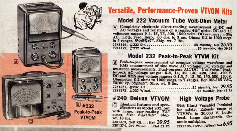
That’s about $440 today!
Anything else?
Here’s a couple of pages of data that were created during the rebuild.
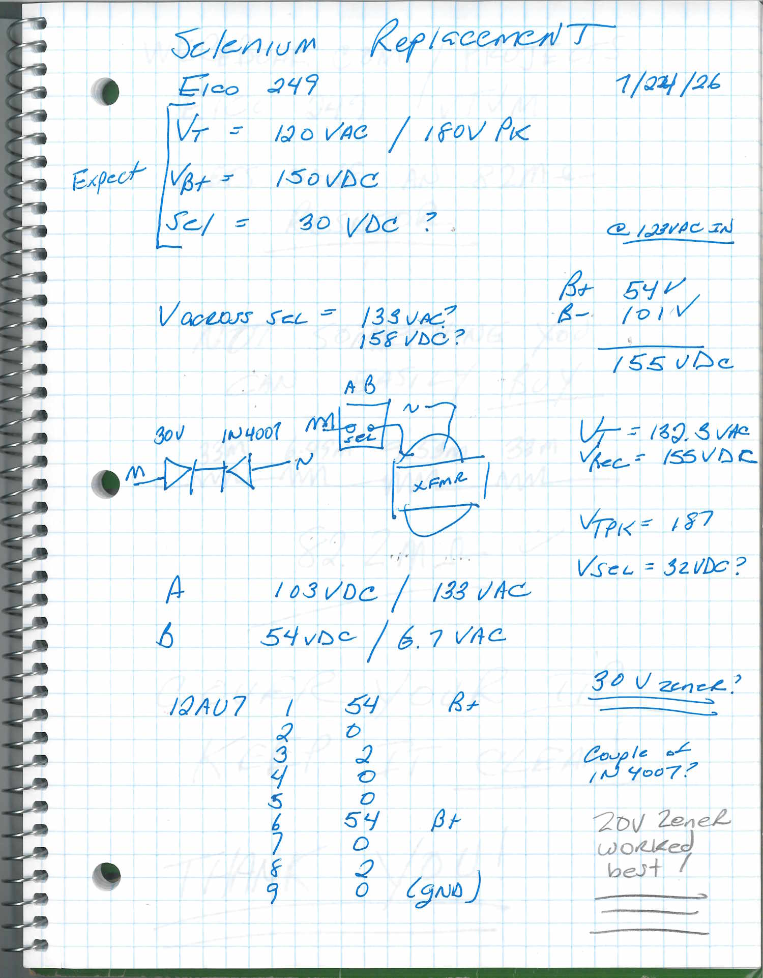
That’s the calculations I used to arrive at the replacement zener in the selenium circuit. I had 30V specified, but 20V actually worked better.
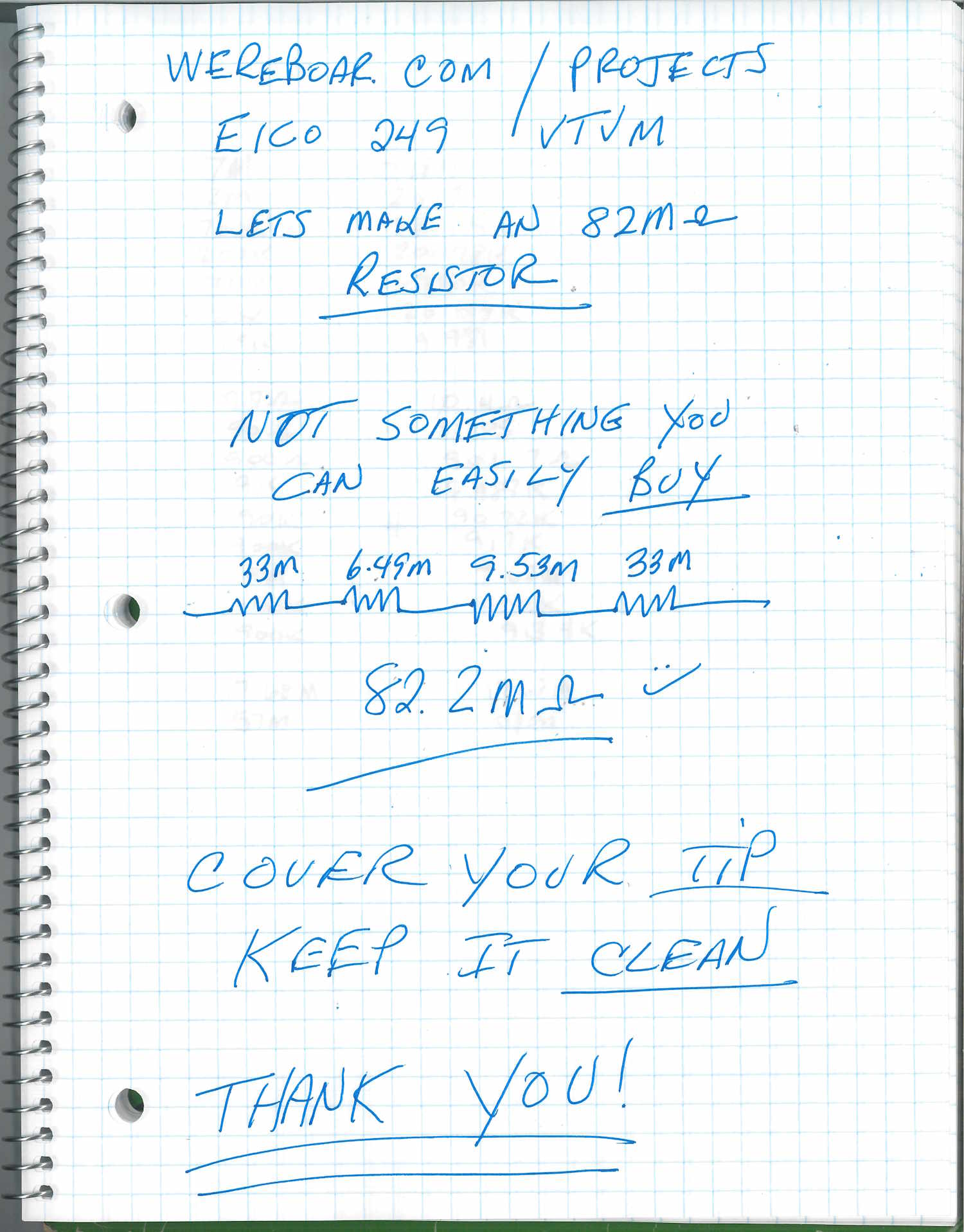
That page was created during the 82MΩ resistor build, and will show up in a video.
That’s all. This wasn’t as bad as I thought, and I now have a large face analog meter with a lot of cool to sit on the bench.
What’s next? A couple of kits, a project for a friend, a Heathkit scope, and a couple of Precise 9071 meters…stay tuned!
The EICO 249 Rebuild series
What’s inside this thing? https://wereboar.com … part-1-observations/
The range switch. https://wereboar.com … d-resistors-therein/
Let’s clean the range switch. https://wereboar.com … ng-the-range-switch/
Starting the rebuild: https://wereboar.com … s-start-the-rebuild/
More resistors for the range switch. https://wereboar.com … or-the-range-switch/
Finishing the range switch. https://wereboar.com … itch-and-next-steps/
Intermission. https://wereboar.com … rmission-whats-next/
Let’s replace the selenium. https://wereboar.com … -rectifier-replaced/
Teardown, part 1. https://wereboar.com … -6a-teardown-part-1/
Teardown, part 2. https://wereboar.com … -6b-teardown-part-2/
A new socket for the 12AU7. https://wereboar.com … ocket-for-the-12au7/
Cleaning the function switch. https://wereboar.com … the-function-switch/
Rebuild, part 1. https://wereboar.com … part-9a-the-rebuild/
Rebuild, part 2. https://wereboar.com … art-9b-the-ac-input/
Rebuild, part 3. https://wereboar.com … inish-this-thing-up/
Let’s test this thing. https://wereboar.com … ets-test-some-parts/
Wrapup and final thoughts: You’re reading it now.
Previous part of this series: https://wereboar.com … testing-the-rebuild/
References
Capacitor kit for this unit: https://www.ebay.com/itm/116116838477
Resistor calculator for unusual values: https://mustcalculat … s/resistorfinder.php
Manual set: https://wereboar.com … with%20schematic.zip
Youtube Playlist: https://www.youtube. … k&list=PLbV6LYdZISZI
The youtube playlist will have the rebuild series in video - this is scheduled to be published some time from now.